Generation 7 Electronics Development
Posted by Traumflug
|
Re: Generation 7 Electronics Development March 08, 2013 12:37PM |
Registered: 11 years ago Posts: 64 |
Quote
peter6960
Yes...
I ticked Enable RX/tax LEDs Untucked enable CTS/RTS - with it ticked auto reset did not work.
Circuit spot on. Works out of the box...
I've been trying to using the 1.5 board with Pronterface, but the only way to do the connection is by enabling CTS/RTS. With this option unchecked I'm be able to connect using gtkterm (or another similar serial terminal), but not Pronterface (Cura sometimes connect, sometimes don't).
I also noticed that MCP2200 baudrate is changed wihen CTS/RTS option is enabled: it's at 19200 before trying to connect using Pronterface, and it's 115200 after that.
I don't know the reason, maybe some Pronterface issues with the python serial module.
Is there any serious hardware problem if this option is enabled?
PS. With this option checked manually reset is needed to do any firmware upload.
|
Re: Generation 7 Electronics Development March 21, 2013 07:45AM |
Registered: 13 years ago Posts: 7,616 |
Does anybody have a good idea on how to make the indicator LEDs of the MOSFETs compatible with 24V?
The current situation is, there's nothing stopping one from operating a Gen7 with 24V for the motors and/or the heaters, except these indicator LEDs. For 12V, they need a pre-resistor 500 to 1000 ohms, for 24V at least 1500 ohms.
Solutions I've though of:
- Make the pre-resistor big and live with less light when operated on 12V.
- Move the indicator LED the the ATmega pin / MOSFET gate side. There's always 5V independently from the heater voltage. Sucks away precious current to fill the MOSFET gate, of course.
- Get rid of the indicator LED altogether. Saves even a few parts.
What do you think?
| Generation 7 Electronics | Teacup Firmware | RepRap DIY |
|
Re: Generation 7 Electronics Development March 21, 2013 08:09AM |
Admin Registered: 16 years ago Posts: 13,886 |
... insert an optocoupler, that 'triggers' from 4V to 24V 
Viktor
--------
Aufruf zum Projekt "Müll-freie Meere" - [reprap.org] -- Deutsche Facebook-Gruppe - [www.facebook.com]
Call for the project "garbage-free seas" - [reprap.org]
Viktor
--------
Aufruf zum Projekt "Müll-freie Meere" - [reprap.org] -- Deutsche Facebook-Gruppe - [www.facebook.com]
Call for the project "garbage-free seas" - [reprap.org]
|
Re: Generation 7 Electronics Development March 21, 2013 11:13AM |
Registered: 11 years ago Posts: 64 |
Quote
Traumflug
The current situation is, there's nothing stopping one from operating a Gen7 with 24V for the motors and/or the heaters, except these indicator LEDs. For 12V, they need a pre-resistor 500 to 1000 ohms, for 24V at least 1500 ohms.
I've no idea, but RAMPS, Megatronics, Azteeg and some other electronics have 1800 ohms resistors for MOSFETs LEDs and usually are operated by 12V in most of the scenarios.
|
Re: Generation 7 Electronics Development March 21, 2013 03:41PM |
Registered: 11 years ago Posts: 121 |
How about just specifying it as option: You solder in based on what you intend running on? No need to change board for that. I use 12v almost exclusively and love the bright LEDs showing heater are on
xoan Wrote:
-------------------------------------------------------
> > The current situation is, there's nothing
> stopping one from operating a Gen7 with 24V for
> the motors and/or the heaters, except these
> indicator LEDs. For 12V, they need a pre-resistor
> 500 to 1000 ohms, for 24V at least 1500 ohms.
>
|
Re: Generation 7 Electronics Development March 22, 2013 03:52AM |
Registered: 15 years ago Posts: 401 |
Or use a constant-current diode instead of a resistor.
e.g. On Semi NSI50010YT1G
Some more info: Constant current diodes are a two-pin device, which is a diode in one direction and a current regulator in the other. They're made by connecting a n-channel jfet with its drain to one terminal, its gate to the other, and a resistor between the gate and the source.
They're known under a number of names:
CCR: Constant Current Regulator (On Semi)
CLD: Current Limiting Diode (Central Semi)
CCD: Constant Current Diode (Vishay)
Though, it seems that Vishay has discontinued their whole line.
OnSemi's line is available through digikey and seems to run from about 2.2mA to 90mA. Obviously, the packages and voltage ratings change a few times in there to account for the power dissipation.
If you're looking for them on Digikey, you end up with some weird results. So, to help you out, they're in:
Product Index > Integrated Circuits (ICs) > PMIC - Current Regulation/Management
Then restrict matches to "Current Regulator"
Edited 1 time(s). Last edit at 03/22/2013 04:05AM by Annirak.
|
Re: Generation 7 Electronics Development March 23, 2013 08:20AM |
Registered: 13 years ago Posts: 7,616 |
Another one answered by PM ("too lazy to translate to english"  ) He suggested using two resistors in series. Additionally a jumper to short one of the resistors when operating at 12V. Sounds reasonable.
) He suggested using two resistors in series. Additionally a jumper to short one of the resistors when operating at 12V. Sounds reasonable.| Generation 7 Electronics | Teacup Firmware | RepRap DIY |
|
Re: Generation 7 Electronics Development March 31, 2013 12:19PM |
Registered: 11 years ago Posts: 121 |
I actually etched up on of Xoan's GEN7S's today
With white painted topside and toner transfered silkscreen it actually looks quite sexy
And compared to a regular Gen 7 - the form factor change did not sound like much on paper, but in reality it really is a lot smaller
And lastly - as most of you know I have a redrawn copy of the Gen 7 in eagle I use for my own botfarm - staying as close to possible to the original in terms of standards and pinouts.
Well, I managed to get the SD card onto the PCB itself (less expansion) and also routed in a 4 pin header for 5v/gnd/sda/scl and another 4 pin for the encoder
Here's a view of the SD (Yamachi FPS300* series SD card holders), placed approx where the endstops on regular Gebn 7 would be.
Think its a nice integration for the main branch... More printrboardish
xoan Wrote:
-------------------------------------------------------
> > - ATX24 and 4 ways on different sides of board.
> So no matter how you try the thicker PSU cables
> has to ho over or under the PCB or other wires. If
> someone finds away to put all power circuitry to
> one side, wiring would be a dream
>
>
> Sure, but I believe a lot of rework would be
> required in order to achieve that. In the smaller
> PCB I've been doing I think that may be
> impossible.
>
>
> - mcp2200 reset. The reenumaration dance gets less
> exciting as time goes on
> - reset switch. Behind USB socket = very difficult
> to reach in emergency or otherwise. Move it closer
> to board edge
>
>
> I've no trouble with MCP2200 reenumeration so
> reset switch can be moved closer to the board edge
> but leaving unaccessible the USB5V output (see
> attached layout).
Edited 1 time(s). Last edit at 03/31/2013 12:19PM by peter6960.
With white painted topside and toner transfered silkscreen it actually looks quite sexy

And compared to a regular Gen 7 - the form factor change did not sound like much on paper, but in reality it really is a lot smaller

And lastly - as most of you know I have a redrawn copy of the Gen 7 in eagle I use for my own botfarm - staying as close to possible to the original in terms of standards and pinouts.
Well, I managed to get the SD card onto the PCB itself (less expansion) and also routed in a 4 pin header for 5v/gnd/sda/scl and another 4 pin for the encoder
Here's a view of the SD (Yamachi FPS300* series SD card holders), placed approx where the endstops on regular Gebn 7 would be.

Think its a nice integration for the main branch... More printrboardish
xoan Wrote:
-------------------------------------------------------
> > - ATX24 and 4 ways on different sides of board.
> So no matter how you try the thicker PSU cables
> has to ho over or under the PCB or other wires. If
> someone finds away to put all power circuitry to
> one side, wiring would be a dream
>
>
> Sure, but I believe a lot of rework would be
> required in order to achieve that. In the smaller
> PCB I've been doing I think that may be
> impossible.
>
>
> - mcp2200 reset. The reenumaration dance gets less
> exciting as time goes on
> - reset switch. Behind USB socket = very difficult
> to reach in emergency or otherwise. Move it closer
> to board edge
>
>
> I've no trouble with MCP2200 reenumeration so
> reset switch can be moved closer to the board edge
> but leaving unaccessible the USB5V output (see
> attached layout).
Edited 1 time(s). Last edit at 03/31/2013 12:19PM by peter6960.
|
Re: Generation 7 Electronics Development April 13, 2013 12:39AM |
Registered: 11 years ago Posts: 69 |
Hi I have finished my GEN7 1.5 board and it passes all the pre test with test software. I have Ardunio 1.0.3, and installed the Gen7+Arduino+IDE+Support+2.1.zip into the hardware folder under the Ardunio folder. Got the Repetier-Firmware ver .82 and found the reference about the TEMP_2_PIN and HEATER_2_PIN. It compiles fine. Uploads fine, but when I try this command M500 in the Pronterface it gives me this message:
Connecting...
start
Printer is now online.
External Reset
>>>M500
SENDING:M500
Error: Missing checksum
continually prints resend.
note - I turned of the wait message for know
Don't now your code and now clue as to where to start looking in it. I now the serial hardware is working as it worked with the test application. even at the 115200 baud rate. So I am thinking its firmware or build Environmen. Any Suggestions? Test programs?
|
Re: Generation 7 Electronics Development April 13, 2013 05:57AM |
Registered: 13 years ago Posts: 7,616 |
Great you got your electronics working flawlessly.
The error you see is indeed a firmware problem. Apparently, Repetier insists on a checksum, but the host doesn't send one. Repetier is active in his own forum section: [forums.reprap.org]
The error you see is indeed a firmware problem. Apparently, Repetier insists on a checksum, but the host doesn't send one. Repetier is active in his own forum section: [forums.reprap.org]
| Generation 7 Electronics | Teacup Firmware | RepRap DIY |
|
Re: Generation 7 Electronics Development April 16, 2013 05:02PM |
Registered: 11 years ago Posts: 121 |
If you still have not managed:
here's my working environment with Repetier - preconfigured for Gen 7 1.5/1.4.1 with SD
[kzn.house4hack.co.za]
here's my working environment with Repetier - preconfigured for Gen 7 1.5/1.4.1 with SD
[kzn.house4hack.co.za]
|
Re: Generation 7 Electronics Development April 18, 2013 11:37AM |
Registered: 11 years ago Posts: 69 |
|
Re: Generation 7 Electronics Development May 01, 2013 01:38AM |
|
Re: Generation 7 Electronics Development May 01, 2013 06:56AM |
Registered: 13 years ago Posts: 7,616 |
Quote
where to read?
What did you do, which bootloader do you use, are you running 16 MHz or 20 MHz, ... ? Answers can only be informative if you describe what you tried.
| Generation 7 Electronics | Teacup Firmware | RepRap DIY |
|
Re: Generation 7 Electronics Development May 01, 2013 06:18PM |
Gen7 v1.5 20 MHz (ATmega 644-20P), [reprap.org]. I need to load the bootloader, used arduino-1.0.3 and Gen7 + Arduino + IDE + Support +2.1
I am a newbie, you can describe the steps? We need to load the first programmer in Gen7 1.5?
Please step by step ... 1, 2, 3 ...., .....
Sorry for bad English.
I am a newbie, you can describe the steps? We need to load the first programmer in Gen7 1.5?
Please step by step ... 1, 2, 3 ...., .....
Sorry for bad English.
|
Re: Generation 7 Electronics Development May 01, 2013 06:22PM |
Registered: 11 years ago Posts: 64 |
|
Re: Generation 7 Electronics Development May 03, 2013 12:02AM |
|
Re: Generation 7 Electronics Development May 03, 2013 10:37AM |
Registered: 11 years ago Posts: 69 |
This is in regards to post 103, looks Good, but you relay do need a good Heat sink on Heater switches. They run a Lot cooler then the melzi board, but tack longer to Heat. and if you run the printer on large prints like 6 hour or more the heat starts to clime, and I have seen up to and above 48C with as big a Heat sink as I can put on them. We cant get mica Insulators hear any more so I needed two separate Heat sinks.
Just some Suggestion, as and Old Electronics man I would Suggest putting only the X, Y, Z, Heated bead, USB and Programing port circuitry on the Main board. Us the Expansion boards for say, Extruders and Hot ends, Blue tooth, NIC, Displays (Tools). Reasoning as its modular. A growing number of people wont to be able to choose 1 - 3 Hot ends. Another concern is 3 Extruders (Drives and Hot ends) can be put on another Processor using I2c or other Serial protocols to transfer the commands to the appropriate module. This levis us with a FW for the main board that Just handles One heat controller, all the Drive stuff and command parsing. Personally, I would like to get and expansion board with Second processor on it and be able to populate it with the electronics for 1, 2 or 3 Extruder drives and heaters.
Another way to look at this is all tools are on expansion boards, and are just routed the tool commands from the main board.
Tools = Extruders & Hot end, Cooling fanes, Secondary command Devices (Blue tooth, NIC, SD Card, Front panels).
Any ways, just the thoughts of and old man (Suggestions, that may be in appropriate).
|
Re: Generation 7 Electronics Development May 04, 2013 10:13AM |
Registered: 13 years ago Posts: 7,616 |
Quote
I have seen up to and above 48C
48 °C is barely above room temperature, isn't it?
In my test series, MOSFETs survived 120 °C measured at the heatsink easily: [reprap.org]
| Generation 7 Electronics | Teacup Firmware | RepRap DIY |
|
Re: Generation 7 Electronics Development May 04, 2013 10:23AM |
Registered: 13 years ago Posts: 7,616 |
P.S.: I agree with the other parts and putting non-basic stuff on the extension board is what I have in mind.
| Generation 7 Electronics | Teacup Firmware | RepRap DIY |
|
Re: Generation 7 Electronics Development May 06, 2013 12:39PM |
Registered: 11 years ago Posts: 69 |
that was 48C with a big heat sink on them. Without the Heat Sink they hotbed one burns your fingers. But more importantly the Connecter for the 12V supply and the board, despite the fact I put ample amounts of solder, is burning. It is also burning the insulation from the power supply on the 12V lead. I could probably up the Voltage to 24V, but I am thinking I am at my max wattage through that connecter. Mite try using a connector for the PCIE power jacks, that doubles up the 12V, both ground and positive. But that would require a new board design. so I will wait till the Connecter burns off the board.
|
Re: Generation 7 Electronics Development May 07, 2013 07:19AM |
Registered: 13 years ago Posts: 7,616 |
Connectors usually haven't a maximum wattage, but a maximum current. So you get double wattage at the same current or half the current at the same wattage.
OK, there's also a maximum voltage rating, but that's 250V for the disk power connectors, far above both, 12V and 24V.
OK, there's also a maximum voltage rating, but that's 250V for the disk power connectors, far above both, 12V and 24V.
| Generation 7 Electronics | Teacup Firmware | RepRap DIY |
|
Re: Generation 7 Electronics Development May 13, 2013 12:51AM |
Registered: 11 years ago Posts: 4 |
|
Re: Generation 7 Electronics Development May 28, 2013 06:12PM |
Registered: 13 years ago Posts: 1,352 |
There is no point fiddling with 2 resistors and jumper and stuff just to make the 24v resistor compatible for led. The If led current is an absolute max rating, worst case scenario, not a minimum, nor something to aim at. Rather something to aim just below it with some safety margin. Simply make the resistor for whatever current it needs for 24v (a little downrating like 90% of max value). Then at 12v, the led will work with same resistor, although will have less current which means is going to light up less, but it still going to provide an indication.
There is no point maxing out the current in the led unless its a power led where the luminous flux matters. But if its just an indicator led, nobody is going to interrogate prisoners with this led in their face, or read books with it, so doesnt matter how bright it is. If it gets just a few mA and it lights up just a notch, its enough to provide an indication that the current passes there and thats all it has to do.
Edit:
But again, 24v wouldnt be exactly the top voltage, that would probably be the lowest between the voltage regulator max and the stepper drivers, probably around 32V so it doesnt get too close to max values (head room for ripple and spikes).
Oh i forgot but also mosfet max DS or breakdown might be a concern, i think some have 30v Vbr so should keep away from that to avoid it leaking, so perhaps 24v is a better maximum than i previously thought.
Edited 2 time(s). Last edit at 05/28/2013 07:20PM by NoobMan.
|
Re: Generation 7 Electronics Development June 11, 2013 07:20AM |
Registered: 13 years ago Posts: 7,616 |
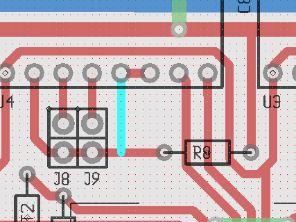
Here's a hack to make a Gen7 (any version) compatible with these early DRV8825-based "Pololus":
This light blue line is an additional track which can be done with a simple solder blob on the real board. It pulls Reset & Sleep always up, a feature missing on these stepper drivers.
That said, Pololu has replaced these early ones already with a version which fixes exactly that: [www.pololu.com]
P.S.: this blob is required for each of the four stepper drivers.
Edited 1 time(s). Last edit at 06/11/2013 07:21AM by Traumflug.
| Generation 7 Electronics | Teacup Firmware | RepRap DIY |
|
Re: Generation 7 Electronics Development June 12, 2013 04:01PM |
Registered: 10 years ago Posts: 25 |
|
Re: Generation 7 Electronics Development June 16, 2013 05:46PM |
Registered: 10 years ago Posts: 6 |
First of: I'm new in this forum. I'd like to thank all the poeple around hwo developed RepRap's.
As the initiator of the forementioned patch Traumflug presented I'd like to suggest other mods.
Traumflug encouraged me to publish my ideas, so I do.
1. Please reroute the traces underneath the SMD-chip. Since we do not have soldermasks you may run in to shortage after soldering the chip.
2. please make 4 holes in the midle of the board. This will be usefull to mount a big heatsink providing improved cooling for the Pololu-drivers.
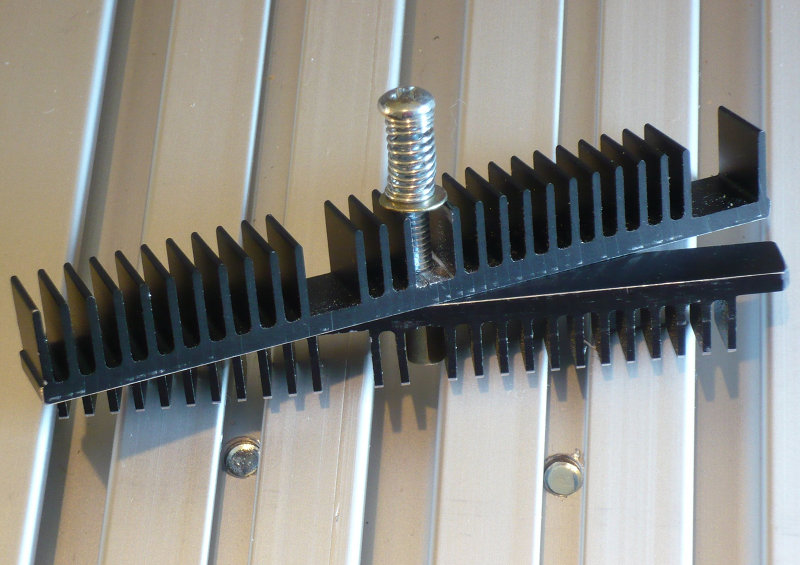
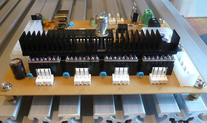
3. Here are pics of my first version of a dualprofil heatsink.
Two bars clamped together holding the 4 Pololu-boards in the middle with the help of a screw and a spring.


This build is not finished jet. I'm awaiting thermal pads and foils to complete the build.
Any hints appreciated.
Edited 8 time(s). Last edit at 06/16/2013 06:40PM by Peter_s.
As the initiator of the forementioned patch Traumflug presented I'd like to suggest other mods.
Traumflug encouraged me to publish my ideas, so I do.
1. Please reroute the traces underneath the SMD-chip. Since we do not have soldermasks you may run in to shortage after soldering the chip.

2. please make 4 holes in the midle of the board. This will be usefull to mount a big heatsink providing improved cooling for the Pololu-drivers.
3. Here are pics of my first version of a dualprofil heatsink.
Two bars clamped together holding the 4 Pololu-boards in the middle with the help of a screw and a spring.
This build is not finished jet. I'm awaiting thermal pads and foils to complete the build.
Any hints appreciated.
Edited 8 time(s). Last edit at 06/16/2013 06:40PM by Peter_s.
|
Re: Generation 7 Electronics Development June 16, 2013 06:04PM |
Registered: 11 years ago Posts: 64 |
Peter_s Wrote:
-------------------------------------------------------
> 1. Please reroute the traces underneath the
> SMD-chip. Since we do not have soldermasks you may
> run in to shortage after soldering the chip.
There is no way to made the trace you show whithout run into a DRC violation.
-------------------------------------------------------
> 1. Please reroute the traces underneath the
> SMD-chip. Since we do not have soldermasks you may
> run in to shortage after soldering the chip.
There is no way to made the trace you show whithout run into a DRC violation.
|
Re: Generation 7 Electronics Development June 16, 2013 06:32PM |
Registered: 10 years ago Posts: 6 |
xoan Wrote:
> There is no way to made the trace you show
> whithout run into a DRC violation.
Hi Xoan.
What about shifting the chip upward a little? This will help smoothing some traces too.
You may consider moving the capacitors too or choose the next size (5mm or 7,5mm raster).
Edited 1 time(s). Last edit at 06/16/2013 06:43PM by Peter_s.
|
Re: Generation 7 Electronics Development June 16, 2013 06:41PM |
Registered: 11 years ago Posts: 64 |
Peter_s Wrote:
-------------------------------------------------------
> xoan Wrote:
>
> > There is no way to made the trace you show
> > whithout run into a DRC violation.
>
> Hi Xoan.
> What about shifting the chip upward a little? This
> will help smoothing some traces too.
> You may consider moving the capacitors too.
The problem is the trace passing between the pads of the same capacitor. This couldn't be solved by moving whatever component in the board


Sorry, only registered users may post in this forum.