Generation 7 Electronics Development
Posted by Traumflug
|
Re: Generation 7 Electronics Development June 16, 2013 06:45PM |
Registered: 10 years ago Posts: 6 |
|
Re: Generation 7 Electronics Development June 16, 2013 07:10PM |
Registered: 11 years ago Posts: 64 |
Peter_s Wrote:
-------------------------------------------------------
> Again, 7mm size?
> If I had the skill to fight with Eagle or whatever
> you use to design thisboard I would give it a try
> before asking others.
Source files for PCB design are in PCB [1] format.
[1] [pcb.geda-project.org]
-------------------------------------------------------
> Again, 7mm size?
> If I had the skill to fight with Eagle or whatever
> you use to design thisboard I would give it a try
> before asking others.
Source files for PCB design are in PCB [1] format.
[1] [pcb.geda-project.org]
|
Re: Generation 7 Electronics Development June 16, 2013 07:29PM |
Registered: 10 years ago Posts: 6 |
I have the board in front of me.
Firstly I will make the reset switch external too.
This is recommended by many users.
With making the switch external we can reduce its pad to two small pads or a two pin header.
This would give room for capacitors using the next size.
Hi xaon, I do not urge you to do the next revision personally.
Probably the Gen7 board will replaced by anothe drive by a more capable chip.
I'm an old man but I'm not a fool. I never gave up, so I do not give up in this case too.
Probably I have to choose a stronger driver board rated with 7A.
Anyway.
Edited 1 time(s). Last edit at 06/16/2013 07:31PM by Peter_s.
|
Re: Generation 7 Electronics Development June 17, 2013 07:52AM |
Registered: 13 years ago Posts: 7,616 |
Thanks for the ideas, @Peter_s.
As you two found out already, changing the track in the suggested way requires a capacitor with a wider pin spacing. Certainly possible, but also introduces a new part. In case one considers the same part with different pin spacing to be a different part.
This area will receive some rework anyways to connect MCP2200s' Reset to 5V USB instead of 5V SB. The patch was mentioned earlier: [forums.reprap.org]
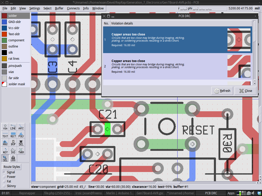
Would an adjustment like this help, too? Tracks for the pins are extended a bit towards the center of the chip, so solder would have to flow a distance before it can bridge an isolation.
As you two found out already, changing the track in the suggested way requires a capacitor with a wider pin spacing. Certainly possible, but also introduces a new part. In case one considers the same part with different pin spacing to be a different part.
This area will receive some rework anyways to connect MCP2200s' Reset to 5V USB instead of 5V SB. The patch was mentioned earlier: [forums.reprap.org]
Would an adjustment like this help, too? Tracks for the pins are extended a bit towards the center of the chip, so solder would have to flow a distance before it can bridge an isolation.

| Generation 7 Electronics | Teacup Firmware | RepRap DIY |
|
Re: Generation 7 Electronics Development June 17, 2013 07:07PM |
Registered: 10 years ago Posts: 6 |
I will not stress this thing further.
I fortunaly finished soldering without making smoke and fire.
But for beginners it may hard to do this work without bridging traces hidden by the chip.
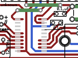
Hey "Traumflug", pls consider increasing the gap between traces if ever possible.
I tinned the whole copper by hand, it was a pain.
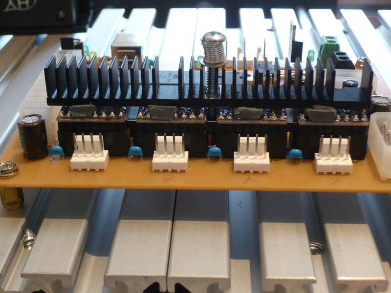
For the solid cnc-machine , the bed depicted above, I ordered a simple commercial controller and 7A rated drivers today.
The Gen7 board will serve for another project.
Probably I will make a "printed" pcb-cnc using the NEMA17 steppers.
This will be a better fit for Pololu-drivers.
factory cyclone mini pcb mill
Edited 1 time(s). Last edit at 06/17/2013 07:07PM by Peter_s.
I fortunaly finished soldering without making smoke and fire.
But for beginners it may hard to do this work without bridging traces hidden by the chip.
Hey "Traumflug", pls consider increasing the gap between traces if ever possible.
I tinned the whole copper by hand, it was a pain.
For the solid cnc-machine , the bed depicted above, I ordered a simple commercial controller and 7A rated drivers today.
The Gen7 board will serve for another project.
Probably I will make a "printed" pcb-cnc using the NEMA17 steppers.
This will be a better fit for Pololu-drivers.

factory cyclone mini pcb mill
Edited 1 time(s). Last edit at 06/17/2013 07:07PM by Peter_s.
|
Re: Generation 7 Electronics Development June 20, 2013 05:57AM |
Registered: 10 years ago Posts: 6 |
Hi,
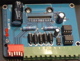
build completed.
It works so far tested with 3 Nema17 steppers ok.

------------
New drivers have arrived.
All those cnc-parts are too expansive, at least in Europe.
This drivers do cost 20 Euro each including shipping from China.
Sell them in the EU and you can make 30 to 50 Euros. Very big margin.

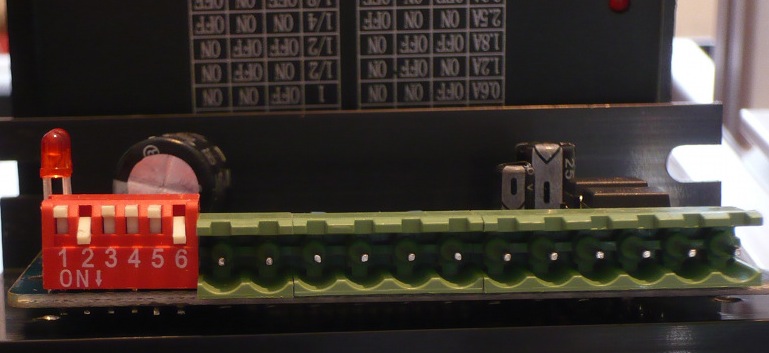
Please note loose boards hold in place by two screws only. Hold at back by the cover cutoff only.

No support, no standoffs.

Next I will try to combine Gen7 board with the new drivers, leave out the weak Pololu-crap.
This leads me to the question, is it possible to make a decent mechanically sturdy stacked unit?
Lets make a sandwich or stack from Gen7 board with 3(4) of the drivers.
The step and dir-signals can be grabbed from the sockets.
Need to make a bunch of cheap connector from stripboard using the same shape as the poloul boards.
Not to difficult to build.
Edited 9 time(s). Last edit at 06/20/2013 06:36AM by Peter_s.
build completed.
It works so far tested with 3 Nema17 steppers ok.
------------
New drivers have arrived.
All those cnc-parts are too expansive, at least in Europe.
This drivers do cost 20 Euro each including shipping from China.
Sell them in the EU and you can make 30 to 50 Euros. Very big margin.
Please note loose boards hold in place by two screws only. Hold at back by the cover cutoff only.
No support, no standoffs.
Next I will try to combine Gen7 board with the new drivers, leave out the weak Pololu-crap.
This leads me to the question, is it possible to make a decent mechanically sturdy stacked unit?
Lets make a sandwich or stack from Gen7 board with 3(4) of the drivers.
The step and dir-signals can be grabbed from the sockets.
Need to make a bunch of cheap connector from stripboard using the same shape as the poloul boards.
Not to difficult to build.
Edited 9 time(s). Last edit at 06/20/2013 06:36AM by Peter_s.
|
Re: Generation 7 Electronics Development June 21, 2013 09:27PM |
Registered: 10 years ago Posts: 2 |
Hello Traumflug,
I have an idea that I would like to share with you, regarding the schematics of the Gen 7 board.
To make things smoother I made a few image files:
First, the state that the Gen 7 is at this given time and the suggestions, highlighted:
Then, we have the modifications to the schematics, just removing the unneded wiring and making sure the connection is still valid:
Lastly (and I don't know if you will approve of this part), the C7 Capacitor / Condensator can be rotated 90 degrees and the wiring on the right, moved for a better flow of the schematics, them not needing to be pulled out any more.
By doing this we obtain: 2 less holes, 1 less bridge, 2 less solders, (things are a little bit easier)
I have attached the files, should you take them into consideration or any iteration in between,
And thank you for the hard work that you have put into everything.
Edited 2 time(s). Last edit at 06/22/2013 08:24AM by Minitehnicus.
I have an idea that I would like to share with you, regarding the schematics of the Gen 7 board.
To make things smoother I made a few image files:
First, the state that the Gen 7 is at this given time and the suggestions, highlighted:

Then, we have the modifications to the schematics, just removing the unneded wiring and making sure the connection is still valid:

Lastly (and I don't know if you will approve of this part), the C7 Capacitor / Condensator can be rotated 90 degrees and the wiring on the right, moved for a better flow of the schematics, them not needing to be pulled out any more.

By doing this we obtain: 2 less holes, 1 less bridge, 2 less solders, (things are a little bit easier)
I have attached the files, should you take them into consideration or any iteration in between,
And thank you for the hard work that you have put into everything.
Edited 2 time(s). Last edit at 06/22/2013 08:24AM by Minitehnicus.
|
Re: Generation 7 Electronics Development June 22, 2013 08:07AM |
Registered: 13 years ago Posts: 7,616 |
Thanks for sharing this, @Minitehnicus. Did you read this: [reprap.org] ?
| Generation 7 Electronics | Teacup Firmware | RepRap DIY |
|
Re: Generation 7 Electronics Development June 22, 2013 09:21AM |
Registered: 10 years ago Posts: 2 |
Traumflug, thank you for the explication, apparently i did not read it, having gained interest in RepRaps right after the Gen7 version 1.4.1 was released.
If the power consumption was lower on the heatbed and extruder it would have been ok.
I have been thinking of other variants but I bet you tried everything to reduce the number of holes in the pcb and doing anything else would just lead to more complicated schematics.
If the power consumption was lower on the heatbed and extruder it would have been ok.
I have been thinking of other variants but I bet you tried everything to reduce the number of holes in the pcb and doing anything else would just lead to more complicated schematics.
|
Re: Generation 7 Electronics Development July 28, 2013 02:37PM |
Registered: 13 years ago Posts: 7,616 |
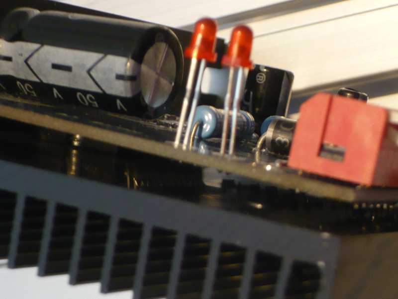
I've just added a pulldown resistor to the gate of the SevenSwitch. A 1 megaohms works just nicely. Measuring heat development of the MOSFET with a heated bed connected showed no measurable additional warming when running 78 Hz PWM. Still, a signal goes away in no visible time if one pulls the signal connector. R3 is the new one:
With the old one, a disconnected signal connector could lead to an overheating MOSFET if 12V and a load were still in place. An ATmega _not_ running a firmware has all pins as input by default, acting just like a disconnected pin. It literally takes minutes until a MOSFET looses its switching charge on its own and all the way down it'll get very very hot.

With the old one, a disconnected signal connector could lead to an overheating MOSFET if 12V and a load were still in place. An ATmega _not_ running a firmware has all pins as input by default, acting just like a disconnected pin. It literally takes minutes until a MOSFET looses its switching charge on its own and all the way down it'll get very very hot.
| Generation 7 Electronics | Teacup Firmware | RepRap DIY |
|
Re: Generation 7 Electronics Development January 17, 2014 10:20AM |
Registered: 10 years ago Posts: 36 |
Hi,
New to rewrap and I am in the planning stages of my build of an Pursa i3 with a modification that I am planning. I am planning an extension to the bed to accommodate two heat beds. My question is will this set of electronics drive the two heaters. I had planned on using a RAMPS but I have been getting feedback that that board will not handle the load of two heaters. Any feedback will be welcomed.
d
|
Re: Generation 7 Electronics Development January 17, 2014 11:48AM |
Registered: 11 years ago Posts: 69 |
There correct, most if not all the electronics barley handle the current load to do ABS, let all own two heating elements. This is of course not tacking into account the power requirement's for two loads. I would suggest two power supplies (30VDC 10A) and two DC to DC SSR (solid state relays). This would handle power requirements and heat the build plate in a descent amount of time. Don't have part number for SSR, I have one on order that looks promising, but not Shure weather it will do the trick or not.
SSR Spec:
40VDC 15A on relay side
3-12vdc trigger.
Will more then likely need to configure the FW for a Bang Bang switch. Although I have read a couple of blogs stating you can control the SSR the same as you would a normal build plate.
In any event hop this helps
SSR Spec:
40VDC 15A on relay side
3-12vdc trigger.
Will more then likely need to configure the FW for a Bang Bang switch. Although I have read a couple of blogs stating you can control the SSR the same as you would a normal build plate.
In any event hop this helps
|
Re: Generation 7 Electronics Development January 17, 2014 01:14PM |
Registered: 10 years ago Posts: 36 |
Will the gen7 board handle it? Or were you talking about all boards? In terms of the relay can you give me a quick schematic? I can follow them but not too good on figuring it out with out one.... 8-(
In total I want to run the motors, several fans, two print heads and two heaters. I currently have a 600 watt server power supply which should be able to run everything. Thanks!
In total I want to run the motors, several fans, two print heads and two heaters. I currently have a 600 watt server power supply which should be able to run everything. Thanks!
|
Re: Generation 7 Electronics Development January 17, 2014 02:34PM |
Registered: 11 years ago Posts: 69 |
wall my Gen7 board burnt the power supply jack trying to run 115C on my build plate (To much current for that jack).
As fare as schematic is concerned, hook one lag of the relay contact to the power supply positive terminal and the other side of the contact to the heatbed. connect the power supply negative terminal to the other Heatbed terminal. connect the signal connections to the Controller paying attention to + and - polarity. Should be able to drive several SSR relays with any Controller including the Gen 7 board. This removes the current needed for the heatbed from the controller board and puts the heave current connections on screw terminals (10A - 15A).
Note - it is worth mentioning the hysteresis of the temperature controller will not be as good as the direct drive approach.
Like I sead I am still waiting for the relay I ordered and a new Aluminum MK3 heatbed.
|
Re: Generation 7 Electronics Development January 18, 2014 06:10AM |
Registered: 13 years ago Posts: 7,616 |
Quote
my Gen7 board burnt the power supply jack trying to run 115C on my build plate (To much current for that jack).
That's right, this jack is the weakest link in the chain. You can solder a screw terminal into the same spot, no PCB layout change required.
Quote
Should be able to drive several SSR relays with any Controller including the Gen 7 board.
That's right, too. The more switches you connect to a single pin, the slower it gets, though. Slower means a hotter MOSFET.
If you can make a Gen7 board, you can make a SevenSwitch, too, and with appropriate screw terminals this should be fine for 16 A. There are several versions of 5mm/5.08mm spaced terminals, they differ in the current they can handle.
| Generation 7 Electronics | Teacup Firmware | RepRap DIY |
|
Re: Generation 7 Electronics Development February 28, 2014 01:29PM |
Registered: 10 years ago Posts: 39 |
|
Re: Generation 7 Electronics Development March 31, 2014 03:31AM |
Registered: 12 years ago Posts: 31 |
Has anybody built Nightfly's Gen7 ExtensionBoard LCD SD FAN? I built one and only have a problem with the SD card. Without a sd card in everything works. When I insert an sd card everything works except when you click the encoder it doesn't do anything. Not sure what the problem is.
Brian
Brian
|
Re: Generation 7 Electronics Development May 05, 2014 10:08AM |
Registered: 10 years ago Posts: 26 |
Hi, I have a problem with the thermistor (Gen7 v1.5).
I have connected this thermistor: [reprap.org]
that are present in Marlin:
But if I have 20°C i see 80°C approximately
Why? I have to set something in the firmware?
And if I want to add the max endstop connected with an expansion board what I have to do?
If I change
Edited 2 time(s). Last edit at 05/05/2014 10:09AM by f1363216.
I have connected this thermistor: [reprap.org]
that are present in Marlin:
// 10 is 100k RS thermistor 198-961 (4.7k pullup)then i setted:
#define TEMP_SENSOR_0 10
But if I have 20°C i see 80°C approximately
Why? I have to set something in the firmware?
And if I want to add the max endstop connected with an expansion board what I have to do?
If I change
#define X_STOP_PIN 0with
#define X_MIN_PIN 0
#define X_MAX_PIN "a free pin"
it works? or I have to do other edits in the firmware?
Edited 2 time(s). Last edit at 05/05/2014 10:09AM by f1363216.
|
Re: Generation 7 Electronics Development May 06, 2014 08:17AM |
Registered: 13 years ago Posts: 7,616 |
@f1363216, this is entirely a firmware question, nothing Gen7 related. I guess it would be a good idea to ask there.
| Generation 7 Electronics | Teacup Firmware | RepRap DIY |
|
Re: Generation 7 Electronics Development November 19, 2014 01:36AM |
Registered: 9 years ago Posts: 45 |
HI
I am very new to this and i wish to make on 3d printer. I don't have much amount to spend for this. Finally i got this forum thread.
I already downloaded files from github: [github.com]
how can i open pcb files. By using which software. because i tried to open .sch file on eagle cad, it's giving some error.
i want to try toner transfer method for making the PCB
Thanks & Regards,
Ben
|
Re: Generation 7 Electronics Development November 25, 2014 10:13AM |
Registered: 13 years ago Posts: 7,616 |
No Eagle please, that's closed source. Gen7 is done in gEDA/pcb.
For toner transfer, see [reprap.org]
For toner transfer, see [reprap.org]
| Generation 7 Electronics | Teacup Firmware | RepRap DIY |
|
Re: Generation 7 Electronics Development January 18, 2015 05:15AM |
Registered: 10 years ago Posts: 102 |
Quote
bentech4u
i want to try toner transfer method for making the PCB
Ben
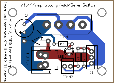
Though this is an old thread, i want to share the negative i created for toner transfer with you guys. Its optimized for TTM as it uses as few acid as possible.
It worked good for me. Use a permanent marker to correct errors with toner transfer.

|
Re: Generation 7 Electronics Development January 19, 2015 05:52AM |
Registered: 13 years ago Posts: 7,616 |
Nice!
Make sure this text on the left side is readable on the final board. There have been people who made a mirrored one.
Make sure this text on the left side is readable on the final board. There have been people who made a mirrored one.
| Generation 7 Electronics | Teacup Firmware | RepRap DIY |
|
Re: Generation 7 Electronics Development January 19, 2015 06:02AM |
Registered: 9 years ago Posts: 45 |
|
Re: Generation 7 Electronics Development January 19, 2015 09:28AM |
Registered: 10 years ago Posts: 102 |

|
Re: Generation 7 Electronics Development April 16, 2015 05:04AM |
Registered: 10 years ago Posts: 23 |
Hi,
Anyone know if any marlin flavour of firmware supports gen 7 electronics with the use of filament diameter sensors such as the one at -->[www.thingiverse.com] by flipper? If not presently are there any plans to support it in the future? I know that makerel only supports the ramps pcb.
Anyone know if any marlin flavour of firmware supports gen 7 electronics with the use of filament diameter sensors such as the one at -->[www.thingiverse.com] by flipper? If not presently are there any plans to support it in the future? I know that makerel only supports the ramps pcb.
|
Re: Generation 7 Electronics Development April 17, 2015 08:26AM |
Registered: 10 years ago Posts: 23 |
Hi,
since sending my previous post I realise that Mackerel firmware is only for use on a filament extruder as opposed to a 3D printer. I have been searching the forums for more info. and see that Marlin at link -->[github.com] is the firmware that supports the sensor. In the configuration.h file of that firmware the motherboards supported are listed as :
Motherboards
* 34 - RAMPS1.4 - uses Analog input 5 on the AUX2 connector
* 81 - Printrboard - Uses Analog input 2 on the Exp1 connector (version B,C,D,E)
* 301 - Rambo - uses Analog input 3
* Note may require analog pins to be defined for different motherboards.
I tried modifying the pins.h file for the Gen 7 1.4 ( which is my board) by adding the lines
#ifdef FILAMENT SENSOR
# define FILWIDTH_PIN 24 // Gen 7 does use AI 7 /D24 which is the physical pin 33 on the ATmega 1284.
# endif
When compiling I get an error that throws me into the temperature.cpp sketch and reports the following error:
There is obviously more to configuring Gen 7 for the filament sensor that I understand. Any help would be gratefully appreciated.
since sending my previous post I realise that Mackerel firmware is only for use on a filament extruder as opposed to a 3D printer. I have been searching the forums for more info. and see that Marlin at link -->[github.com] is the firmware that supports the sensor. In the configuration.h file of that firmware the motherboards supported are listed as :
Motherboards
* 34 - RAMPS1.4 - uses Analog input 5 on the AUX2 connector
* 81 - Printrboard - Uses Analog input 2 on the Exp1 connector (version B,C,D,E)
* 301 - Rambo - uses Analog input 3
* Note may require analog pins to be defined for different motherboards.
I tried modifying the pins.h file for the Gen 7 1.4 ( which is my board) by adding the lines
#ifdef FILAMENT SENSOR
# define FILWIDTH_PIN 24 // Gen 7 does use AI 7 /D24 which is the physical pin 33 on the ATmega 1284.
# endif
When compiling I get an error that throws me into the temperature.cpp sketch and reports the following error:
Quote
'DIDR2' was not declared in this scope.
There is obviously more to configuring Gen 7 for the filament sensor that I understand. Any help would be gratefully appreciated.
|
Re: Generation 7 Electronics Development October 22, 2015 12:53PM |
Registered: 12 years ago Posts: 44 |
I would like to get rid of the bulk and extra wires of my ATX power supply. I have some spare laptop power supplies that supply 20V up to 170W. I already have one supplying the motor power supply on my Gen7 v1.3 board, but I want to put a 2nd one on the hotend and bed supply. Now, the MK2a bed usually draws 120W @ 12v and the hotend is 25W at 12v, for a total of 145W. If I just hook up 20V to the same components, it's going to shoot up to over 400W and probably burn something out.
So instead I can purchase a new heater cartridge, new bed and new power supply to run these all at 24v, nice and safe.
But I am a software engineer. So I am naturally thinking the easiest path instead would be to limit the PWM drivers on the Gen7 to a maximum 60% duty cycle and then run the 20V through my existing bed and heater cartridge.
I'm trying to find the right balance between "cheapskate using recycle parts" and "you're insane and going to kill yourself with this".
What do you think? Am I crazy?
Also, am I correct in thinking that I can remove the ATX completely after such a mod, assuming I can find a different source (perhaps a 7805) for the 5v AVR supply?
|
Re: Generation 7 Electronics Development October 22, 2015 03:44PM |
Registered: 13 years ago Posts: 7,616 |
Do it, report how it works, form a nice patch for Teacup Firmware, including its Configtool.
| Generation 7 Electronics | Teacup Firmware | RepRap DIY |
|
Re: Generation 7 Electronics Development December 13, 2015 09:57AM |
Registered: 8 years ago Posts: 338 |
Hello,
I tried to get in touch with geda - and succeeded to create my own symbols and schematics, but I'm completely trapped in creating footprints.
I even failed to use downloaded footprints ...
pcb finds them, but gsch2pcb does not.
Is anybody out there to shine me a light on how to create and use own footprints?


Sorry, only registered users may post in this forum.