Generation 7 Electronics Development
Posted by Traumflug
|
Re: Generation 7 Electronics Development October 29, 2010 10:32PM |
Registered: 13 years ago Posts: 228 |
Mike,
Thank you for the pointing me in the right direction! I am beginning to see what is going on.
I was indeed getting this short-circuit problem when doing the "optimize rats nest". I just verified it is inherited from Traumflug's git source. Will try the suggested cure.
My aim is of course to have a single sided board that I can engrave with the CNC. I do not mind if It has some vias and "zero ohm resistors" on the other side of course.
L.
|
Re: Generation 7 Electronics Development October 30, 2010 02:54AM |
Registered: 13 years ago Posts: 7,616 |
Quote
Your schematic has the limits stops as ground, signal, power, but your PCB layout has them ground, power signal.
Yupp, this is the result of the recent 90 deg turn of the headers to simplify the PCB. While simplifications are always welcome, it comes at the cost of the incompatibility with Gen236 Opto Endstops (didn't actually check Gen6 yet). This turn was done in pcb only, the schematic has yet to follow.
Quote
going between pins
First tests with PCB milling found, that a gap of 0.4 mm between paths and a path width of also 0.4 mm is required for manufacturing on a RepRap. For now, the PCB is roughly compatible with this boundary, even if not perfected everywhere. Header pins are spaced 2.54 mm and need 1.0 mm drill holes. Drill hole 1.0 mm + 1x path + 2x gap = 2.2 mm leaves just 0.34 / 2 = 0.17 mm copper ring for each pin. It _might_ work ...
| Generation 7 Electronics | Teacup Firmware | RepRap DIY |
|
Re: Generation 7 Electronics Development October 30, 2010 09:12AM |
Registered: 14 years ago Posts: 1,092 |
Note that RAMPS has the optos as Power, Ground, Signal.
It might be prudent to stick to the same pinout if you're not going to use the Gen2/3 layout. This way, cables made for one work on the other, and don't inadvertently swap power/ground, blowing an opto. Hopefully this should be a minor change.
Note: The Gen2/3 layout was bad anyway, as it is easy to put a cable on backwards and blow an opto (as it swaps power/ground).
|
Re: Generation 7 Electronics Development October 30, 2010 07:39PM |
Registered: 14 years ago Posts: 380 |
If we need to go back to ground, signal, power to be compatible with board generations and cables, that will mean jumpering every opto-connector. I would recommend using the jumper on the signal as it is the lowest current of the three pins.
I fully understand dumbing down the design to allow for reprap pcb milling. I had forgotten that that was a major goal for this board. Given that, yes the skinny lines are right out. And that means that Lanthan's solution to the ISP programming connector is probably the best approach.
I fully understand dumbing down the design to allow for reprap pcb milling. I had forgotten that that was a major goal for this board. Given that, yes the skinny lines are right out. And that means that Lanthan's solution to the ISP programming connector is probably the best approach.
|
Re: Generation 7 Electronics Development October 31, 2010 06:09AM |
Registered: 14 years ago Posts: 1,092 |
I personally think that the Gen2/3 way was dumb, as getting a cable the wrong way switches power/ground and you would blow an opto. No ifs, no buts.
Putting it the same way as the RAMPS boards do (which is, power/ground/signal) at least gives this design the same setup as the RAMPS boards, and ensures some sort of consistency between multiple types of electronics.
ie: If you are going to change it, if possible stick to the way the RAMPS board does it. That way, any cables for RAMPS will "just work" with your setup.
|
Re: Generation 7 Electronics Development October 31, 2010 07:49AM |
Registered: 13 years ago Posts: 833 |
I'd do (and in fact did) it still another way:
Don't use these H2...LOB and LOL. They are not that easy to get.
Use a generic light "barrier" as end stop.
Provide the R to drive the LED of said device.
Put a 74HC14 on the board to have a schmitt-trigger for a well-defined trigger point.
Provide the R to be used as a voltage divider at the input of the HC14.
Then use a shielded cable to connect the three pins with the end stop.
|
Re: Generation 7 Electronics Development November 06, 2010 06:27AM |
Registered: 13 years ago Posts: 228 |
20101106_Traumflug-Generation_7_Electronics.zip
I think I got the ICSP header right now (layout pin numbers modified in the library), and a bit less jumpering. Also got all of the endstop connectors harmonized to a 1 GND 2 +VCC 3 SIGNAL both in the schematics and the PCB.
Couldn't change the pinout of TEMP and TEMP1
Most bad rats are gone, but still getting a couple of warnings:
Warning! net "+5V" is shorted to net "GND"
Warning! net "+5V" is shorted to net "GND"
Warning! net "GND" is shorted to net "+5V"
Warning! net "unnamed_net1" is shorted to net "unnamed_net74"
Warning! net "unnamed_net74" is shorted to net "unnamed_net1"
1 rat line remaining
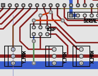
Can you help me finding where the problems are? I see orange warnings on CT2, Z_MAX, ICSP pin 2 and pin 6. There is an unwanted rat line on E-MOT C13 (haven't audited this part yet).
Some thoughts:
Thank you.
Edited 1 time(s). Last edit at 11/06/2010 06:30AM by Lanthan.

I think I got the ICSP header right now (layout pin numbers modified in the library), and a bit less jumpering. Also got all of the endstop connectors harmonized to a 1 GND 2 +VCC 3 SIGNAL both in the schematics and the PCB.
Couldn't change the pinout of TEMP and TEMP1
Most bad rats are gone, but still getting a couple of warnings:
Warning! net "+5V" is shorted to net "GND"
Warning! net "+5V" is shorted to net "GND"
Warning! net "GND" is shorted to net "+5V"
Warning! net "unnamed_net1" is shorted to net "unnamed_net74"
Warning! net "unnamed_net74" is shorted to net "unnamed_net1"
1 rat line remaining
Can you help me finding where the problems are? I see orange warnings on CT2, Z_MAX, ICSP pin 2 and pin 6. There is an unwanted rat line on E-MOT C13 (haven't audited this part yet).
Some thoughts:
- Motherboard power connectors are expensive and not that easy to find, I'd like to replace them with screw terminals.
- The microstepping jumper bases look really small (or is it my idea?), I'd like to replace each one of them with a 2x3 line of standard headers
- Maybe screw terminals might be good for HEATER1, HEATER2 and FAN1 too.
- Might be a good thing to reinforce ground plates and shielding...
Thank you.
Edited 1 time(s). Last edit at 11/06/2010 06:30AM by Lanthan.
|
Re: Generation 7 Electronics Development November 06, 2010 07:12AM |
Registered: 13 years ago Posts: 7,616 |
Quote
Most bad rats are gone, but still getting a couple of warnings:
There's a difference between the 5 volts coming in from 5VSB through fuse R15 and the "regular" 5V coming in through fuse R17. This should allow to turn the PSU on and off with the ATmega, but in the Gen2OnABoard Wiki page is some talk about this idea not working. No definite answer yet :-}
For seeing a working solution regarding the rats, you may want to have a look at the Github repo. You can even hit the "d" keyboard key while the mouse is over the ICSP connector to see this header's pinout. I've pushed this on Oct. 30 already, but forgot to mention the push here.
[*] Motherboard power connectors are expensive and not that easy to find, I'd like to replace them with screw terminals.
My personal experience showed screw terminals to be pretty unreliable, especially the cheap ones.
One solution is to unsolder the power connector from the computer you stole the power supply from, the other is to add a generic 12V "wall wart" connector in conjunction with an LM7805 voltage reducer. Third option would be 5V from USB, but there's no USB, yet ;-)
[*] The microstepping jumper bases look really small (or is it my idea?), I'd like to replace each one of them with a 2x3 line of standard headers
Look at earlier versions, there we had standard jumpers already. There's almost no reason to set them to something else than 1/16 microstepping, though.
[*] Maybe screw terminals might be good for HEATER1, HEATER2 and FAN1 too.
See above.
[*] Might be a good thing to reinforce ground plates and shielding...
Of course.
| Generation 7 Electronics | Teacup Firmware | RepRap DIY |
|
Re: Generation 7 Electronics Development November 08, 2010 01:49PM |
Registered: 14 years ago Posts: 380 |
For high current connections, I still prefer screw terminals to slide on connectors. In my car, the AC fan keeps burning through the spade style connectors. With proper termination of the heater power leads using a crimp or solder connectior you should have very reliable power transfer, and easy connecting and disconnecting of the leads when needed. I agree that stranded wire going straight into a screw connector is bad, but the problem is with the thin strands, not the screw connector. It creates and air tight connection with high current load capability. Remember that house wiring, at least here in the U.S., is based on screw connectors, not sliding contact connectors.
Mike
Mike
|
Re: Generation 7 Electronics Development November 08, 2010 09:43PM |
Registered: 13 years ago Posts: 1,352 |
|
Re: Generation 7 Electronics Development November 08, 2010 10:55PM |
Admin Registered: 17 years ago Posts: 1,791 |
Apparently:
http://geda.seul.org/wiki/geda:download
it doesn't run on windows without some tinkering.
I'd suggest running ubuntu linux, via
dual boot: [help.ubuntu.com]
ubuntu inside windows: [ubuntumanual.org]
or a
live cd: [help.ubuntu.com]
If you have trouble with this, the folk in ubuntu's forum and mailing lists can help you out.
-Sebastien, RepRap.org library gnome.
Remember, you're all RepRap developers (once you've joined the super-secret developer mailing list), and the wiki, RepRap.org, [reprap.org] is for everyone and everything!
|
Re: Generation 7 Electronics Development November 08, 2010 11:44PM |
Registered: 16 years ago Posts: 1,094 |
I really enjoyed the handyboard's sensor connectors. basically GND, power, NC, signal so if you plug it in backwards, power doesn't connect to anything at all and nothing can blow. Also, it's more easily keyable to avoid incorrect insertion in the first place
-----------------------------------------------
Wooden Mendel
Teacup Firmware
-----------------------------------------------
Wooden Mendel
Teacup Firmware
|
Re: Generation 7 Electronics Development November 09, 2010 07:21AM |
Registered: 14 years ago Posts: 248 |
rocket_scientist Wrote:
-------------------------------------------------------
> For high current connections, I still prefer screw
> terminals to slide on connectors. In my car, the
> AC fan keeps burning through the spade style
> connectors. With proper termination of the heater
> power leads using a crimp or solder connectior you
> should have very reliable power transfer, and easy
> connecting and disconnecting of the leads when
> needed. I agree that stranded wire going straight
> into a screw connector is bad, but the problem is
> with the thin strands, not the screw connector. It
> creates and air tight connection with high current
> load capability. Remember that house wiring, at
> least here in the U.S., is based on screw
> connectors, not sliding contact connectors.
>
> Mike
That sounds like more of a problem with the fan than the connectors, basically its drawing too much current, so either the stator coil is shorting or the brushes need changing.
In Automotive = new fan.
|
Re: Generation 7 Electronics Development November 12, 2010 05:02PM |
Registered: 13 years ago Posts: 228 |
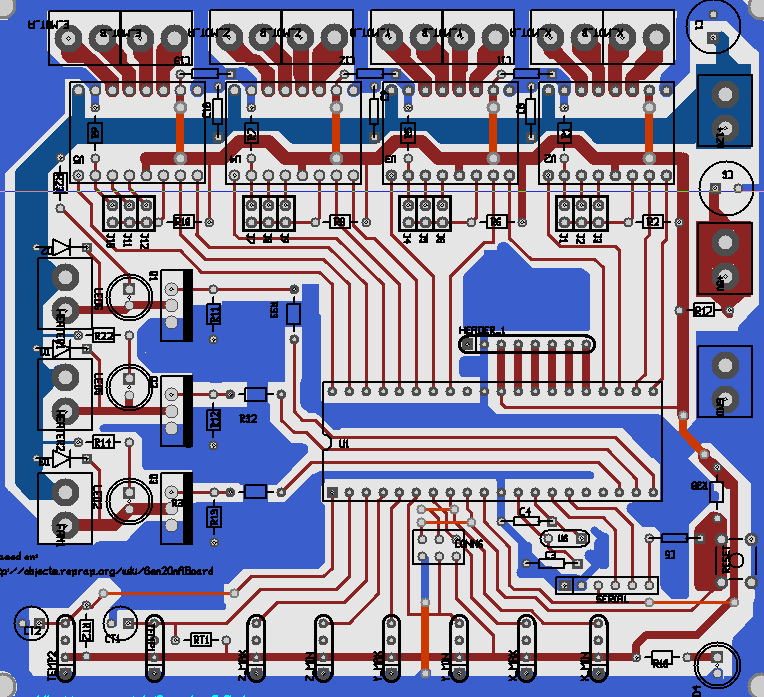
I more or less finished adapting this thing to my needs and preferences. Learnig, slowly. No more rats at least.
I expect to use it with a FTDI cable.
My changes:
* Gone are the ATX connector and specialized 5V circuit. I have no need for this. Less components, less hassle.
* Screw connectors (that is what I have in stock, and that is what has worked best for me till now) to connect any power supply: +12V (dual), +5V (dual) and GND (dual).
* Screw connectors for both heaters and fan.
* Screw connectors for the stepper driver terminals
* Reattached the stepper driver's ENABLE pins. I see some need for this, and several reprap electronics appear to use 'em.
* real jumper headers to experiment with different microstepping settings. According to some sources, the processor isn't up to the task of dealing with multi-axis 16x mincrostepping
* Some pin changes on the main chip.
Still too many different drill sizes. Will have to deal with that.
Thanks to all for the input!
20101112_Generation_7_simplified.zip
Note in margin: I recently had a look at the Teensy board, appears to have "real" USB, price is still reasonable. Interesting for reprap purposes?
L.
I expect to use it with a FTDI cable.

My changes:
* Gone are the ATX connector and specialized 5V circuit. I have no need for this. Less components, less hassle.
* Screw connectors (that is what I have in stock, and that is what has worked best for me till now) to connect any power supply: +12V (dual), +5V (dual) and GND (dual).
* Screw connectors for both heaters and fan.
* Screw connectors for the stepper driver terminals
* Reattached the stepper driver's ENABLE pins. I see some need for this, and several reprap electronics appear to use 'em.
* real jumper headers to experiment with different microstepping settings. According to some sources, the processor isn't up to the task of dealing with multi-axis 16x mincrostepping
* Some pin changes on the main chip.
Still too many different drill sizes. Will have to deal with that.
Thanks to all for the input!

20101112_Generation_7_simplified.zip
Note in margin: I recently had a look at the Teensy board, appears to have "real" USB, price is still reasonable. Interesting for reprap purposes?
L.
|
Re: Generation 7 Electronics Development November 13, 2010 12:56AM |
Registered: 14 years ago Posts: 1,092 |
Looks like you've stuck to 2.54mm and 5.08mm pitch connectors/screw terminals, which gives people choice. If you'd gone and used those stupid 4mm pitch connectors, then things would be annoying.
Note: You can get nice plug/socket pin connectors that are 5.08mm pitch, and standard SIL headers are 2.54mm pitch if you don't want to use those locking style polarised connectors.
Note: You can get nice plug/socket pin connectors that are 5.08mm pitch, and standard SIL headers are 2.54mm pitch if you don't want to use those locking style polarised connectors.
|
Re: Generation 7 Electronics Development November 14, 2010 05:04PM |
Registered: 16 years ago Posts: 438 |
Random comments. This isn't my area of expertise, I'm more a software guy, but looking over your plan, I notice the following:
It looks like if you scoot the TIP120 things (uhm, also called MOSFETs) down a smidge you'll save a bridge, where there's a long skinny one just because it couldn't fit in between the existing ones.
The crystal is *under* the processor socket? Does that even work? I'd think that it wouldn't work at all when the chip is soldered directly onto the board.
The connector for the temp sensors have +5V on one side, while the endstops have it in the middle. Since there was that earlier discussion about the damaging effects of plugging things in backwards, is this right?
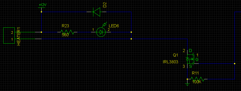
There's a diode for each of the MOSFETs, is that really needed? I though that was only for driving inductive loads, which the heater ain't. And if the heater *is* and inductive load, are three separate diodes still needed? Your ground track to them is so very wide that I'd think it'd never actually trip the diode. I suppose that it would be easy to simply not populate them when your heater isn't inductive.
--
I'm building it with Baling Wire
It looks like if you scoot the TIP120 things (uhm, also called MOSFETs) down a smidge you'll save a bridge, where there's a long skinny one just because it couldn't fit in between the existing ones.
The crystal is *under* the processor socket? Does that even work? I'd think that it wouldn't work at all when the chip is soldered directly onto the board.
The connector for the temp sensors have +5V on one side, while the endstops have it in the middle. Since there was that earlier discussion about the damaging effects of plugging things in backwards, is this right?
There's a diode for each of the MOSFETs, is that really needed? I though that was only for driving inductive loads, which the heater ain't. And if the heater *is* and inductive load, are three separate diodes still needed? Your ground track to them is so very wide that I'd think it'd never actually trip the diode. I suppose that it would be easy to simply not populate them when your heater isn't inductive.
--
I'm building it with Baling Wire
|
Re: Generation 7 Electronics Development November 14, 2010 06:52PM |
Registered: 16 years ago Posts: 1,094 |
don't assume that loads aren't inductive enough to cause a problem- even a long length of wire has some inductance, and many heaters are wound in coils. Even the resistor heaters use wirewound resistors! Note all the posts in the forums about people's mosfets blowing up because they were supposed to be protected ones but they only got normal ones that need an external diode. They only need to be overvolted for a nanosecond to be damaged. The diode is a small price to pay for necessary mosfet protection from inductance.
Remember to use logic-level mosfets! IRL3803 work great for me- 16A w/ no heatsink at Vgs=4.5v. Some copper on the top of the board may help with heatsinking if you want it, but be aware that the tab is internally connected to the middle pin!
I still think GND-5v-NC-SIG is the best way to wire sensors- inserting backwards doesn't damage anything at the cost of a little board space.
-----------------------------------------------
Wooden Mendel
Teacup Firmware
|
Re: Generation 7 Electronics Development November 16, 2010 03:55AM |
Registered: 13 years ago Posts: 228 |
Thx for input.
The Voronoi trace isolation is looking good (or at least, psychedelic ).
).
I thik I'll further rework it to get rid of some mentioned connector oddities, harmonize pinouts, etc. (preferences?). Must also check the size of the copper plates I have. At least, the pgbtogecode toolchain appears to be generating usable results. I hope the drilling ops aren't mirrored against the routing ops.
For some structural reason(?), the TIP-120 are labeled as power "epitaxial darlington transistor" rather than MOS field effect transistor,
http://www.fairchildsemi.com/ds/TI%2FTIP122.pdf
I've seen some arduino projects using 'em to drive DC motors et al. They are supposed to have several internal protections, diodes resistors et al. but as Triffid Hunter points out, it isn't a bad idea to add external diodes.
Woud you please further discuss the respective advantages and tradeoffs of logic-level FETs (like the IRLZ thingies above mentioned) against TIP-120s? Any expected behaviour differences driving things with pwm?
Also: we could reclaim some real state space (and maybe routing sanity?) by setting them up orthogonally to the board and using an aluminium profile as a heatsink. Like in many or most "commercial" electronics of the gone years...
L.
The Voronoi trace isolation is looking good (or at least, psychedelic
). 

I thik I'll further rework it to get rid of some mentioned connector oddities, harmonize pinouts, etc. (preferences?). Must also check the size of the copper plates I have. At least, the pgbtogecode toolchain appears to be generating usable results. I hope the drilling ops aren't mirrored against the routing ops.
For some structural reason(?), the TIP-120 are labeled as power "epitaxial darlington transistor" rather than MOS field effect transistor,
http://www.fairchildsemi.com/ds/TI%2FTIP122.pdf
I've seen some arduino projects using 'em to drive DC motors et al. They are supposed to have several internal protections, diodes resistors et al. but as Triffid Hunter points out, it isn't a bad idea to add external diodes.
Woud you please further discuss the respective advantages and tradeoffs of logic-level FETs (like the IRLZ thingies above mentioned) against TIP-120s? Any expected behaviour differences driving things with pwm?
Also: we could reclaim some real state space (and maybe routing sanity?) by setting them up orthogonally to the board and using an aluminium profile as a heatsink. Like in many or most "commercial" electronics of the gone years...
L.
|
Re: Generation 7 Electronics Development November 16, 2010 06:44PM |
Registered: 14 years ago Posts: 1,092 |
TIP 120's (and even TIP 122's) drop a fair chunk of voltage across them when driving current.
MOSFETS (such as the STP55NF06L used in RAMPs and many Arduino shield designs) drop a lot less voltage. In FETs, this is due to their low RDS(on) value, which is the resistance across the device (source to drain) when in the "on" state.
As such, they don't get anywhere near as hot driving high current loads. This works very nicely with PWM, as you get more 'instant' current a switch-on from the same supply voltage.
|
Re: Generation 7 Electronics Development November 17, 2010 04:00PM |
Registered: 14 years ago Posts: 380 |
Lanthan,
The TIP-120s are power darlington transistor pairs. If you look at the spec sheet, you will see that for currents of several amps, the collector-emitter voltage is over 1 volt. If you needed 4 amps to drive the stepper motors (the maximum that this device can handle), that would be 1.1volts times 4 amps = 4.4watts dissipated across the device. That is equivalent to the MOSFET's on resistance of 1.1volts/4amps = 0.275 ohms equivalent.
For the STP55NF06L, the spec sheet can sustain 55amps, and has an 'On' resistance of 0.018 ohms. The same 4 amp current would dissipate is current squared times resistance or 16 * 0.018 = 0.288 watts. This means that the MOSFET wastes 1/10th the power that the power darlington pair does, and has 10 times the max current capacity. However, the STP55NF06L has no internal protection.
The previously mentioned IRL3803 has an internal protection diode and a very low on resistance of 0.0055 ohms. This one can handle 150Amps of current, and wastes only 1/3 the power that the STP55NF06L does.
So the main difference between the TIP-120 and the MOSFETS is how much power is lost across the device when it is turned on, and how high a max current it can handle. Some of the other MOSFETS have higher gate voltages, and require a MOSFET driver chip with capacitors to generate the higher gate voltage needed off a 5 volt supply. Others have internal thermal overload protection as well as better back-emf diodes.
|
Re: Generation 7 Electronics Development November 18, 2010 04:32AM |
Registered: 13 years ago Posts: 228 |
You guys have convinced me ;-) let's go for Mosfets, IRL3803 seems OK.
To Rocket Scientist: we need the power transistors/mosfets to drive heaters, fans, in my case also a small dc spindle... as for the stepper motor part, is is entirely dealt with the four pololu/a3983 stepper drivers on top.
Last night I started doing the modifications to the schematic and the board, also got that crystal from under the processor and near the clock pins: the clock lines, in my undestanding, should be kept short.
The three mosfets will be connected to PWM-capable pins (18, 19 and 20 which are free), this was not the case in the previous implementation. Now the "best" placement for the mostfets would be at the right side of the board... Meh. we'll see. Hope to post some results in the next days.
L.
|
Re: Generation 7 Electronics Development November 18, 2010 05:21AM |
Registered: 13 years ago Posts: 7,616 |
Quote
Last night I started doing the modifications to the schematic and the board, also got that crystal from under the processor and near the clock pins: the clock lines, in my undestanding, should be kept short.
Yes, shorter lines are better. Putting the crystal to the side allowed for a via free design of this part, that's why I've put it in this area.
Lanthan, do you have a Github account as well? The unfortunate truth is, electronic designs can't handle collaborative work as well as software source code, because merging is almost impossible. I'd like to try anyways.
| Generation 7 Electronics | Teacup Firmware | RepRap DIY |
|
Re: Generation 7 Electronics Development November 19, 2010 02:55AM |
Registered: 16 years ago Posts: 1,094 |
remember a resistor between atmega output and mosfet gate- (warning! gross simplification ahead!) the gate looks like a ~2nF capacitor, so it can take significant current to change quickly, and puts a fair load on the uC's output drivers! 10 to 22 ohms (not kiloohms!) seems to be common for uC -> mosfet gate.
I skipped it in my electronics and they work, but it's not good for reliability.
-----------------------------------------------
Wooden Mendel
Teacup Firmware
I skipped it in my electronics and they work, but it's not good for reliability.
-----------------------------------------------
Wooden Mendel
Teacup Firmware
|
Re: Generation 7 Electronics Development November 19, 2010 02:40PM |
Registered: 13 years ago Posts: 228 |
Traumflug: Thx for the invitation, I'll make a github account, hopefully this WE... yes merges seem to be more involved than for "just code"... yet they are all text files.
I think I have come to a solution for the crystal and related condensors approaching Atmel's recommendations, mostly surrounded with ground and near the pins
Triffid Hunter: good suggestion! Indeed I had'nt seen this in the various schematics floating around, moreover this would save us 3 vias!
I was projecting to use 100K resistors to clamp the gate to ground, this is supposed to improve reliability too. Does it sound appropriate? Compatible with your proposal?
Connectors for endstops and temperature: going for 4 pins everywhere for all, GND/+5V/NC/SIGNAL, as has been recommended.
L.
I think I have come to a solution for the crystal and related condensors approaching Atmel's recommendations, mostly surrounded with ground and near the pins
Triffid Hunter: good suggestion! Indeed I had'nt seen this in the various schematics floating around, moreover this would save us 3 vias!
I was projecting to use 100K resistors to clamp the gate to ground, this is supposed to improve reliability too. Does it sound appropriate? Compatible with your proposal?

Connectors for endstops and temperature: going for 4 pins everywhere for all, GND/+5V/NC/SIGNAL, as has been recommended.
L.
|
Re: Generation 7 Electronics Development November 19, 2010 08:36PM |
Registered: 13 years ago Posts: 228 |
And here are the latest files with the above mentioned changes.
Also, just in case one might find some uses for the unused pins, there is a keyable header with 5 lines +5V and GND.
20101120_Generation_7_simplified.zip
L.
Also, just in case one might find some uses for the unused pins, there is a keyable header with 5 lines +5V and GND.
20101120_Generation_7_simplified.zip

L.
|
Re: Generation 7 Electronics Development November 20, 2010 01:45AM |
Registered: 16 years ago Posts: 1,094 |
adding a 100k pull-down should help when powered off, and during start-up when the pin is an input. after that it should have no effect. I recommend adding it.
-----------------------------------------------
Wooden Mendel
Teacup Firmware
-----------------------------------------------
Wooden Mendel
Teacup Firmware
|
Re: Generation 7 Electronics Development November 20, 2010 08:05AM |
Registered: 13 years ago Posts: 228 |
Triffid_Hunter Wrote:
-------------------------------------------------------
> adding a 100k pull-down should help when powered
> off, and during start-up when the pin is an input.
> after that it should have no effect. I recommend
> adding it.
It is there! (R11, R12 and R13 are 100K, between GND and the gate)
-------------------------------------------------------
> adding a 100k pull-down should help when powered
> off, and during start-up when the pin is an input.
> after that it should have no effect. I recommend
> adding it.
It is there! (R11, R12 and R13 are 100K, between GND and the gate)
|
Re: Generation 7 Electronics Development November 22, 2010 02:53PM |
Registered: 14 years ago Posts: 30 |
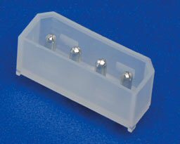
Is there any chance we could look again at adding a PC molex-type connector? From looking at the board design, It seems that if the 5v line was extended a bit, one could easily fit in the top-left of the board, and provide +12v, gnd and +5v.
This would allow people the choice of using screw terminals or just plugging in a PC power supply.
I've attached a photo of the type of connector i was thinking of.
This would allow people the choice of using screw terminals or just plugging in a PC power supply.
I've attached a photo of the type of connector i was thinking of.
|
Re: Generation 7 Electronics Development November 22, 2010 05:20PM |
Registered: 13 years ago Posts: 228 |
|
Re: Generation 7 Electronics Development November 23, 2010 08:46AM |
Registered: 14 years ago Posts: 30 |


Sorry, only registered users may post in this forum.