Generation 7 Electronics Development
Posted by Traumflug
|
Re: Generation 7 Electronics Development November 24, 2010 05:30PM |
Registered: 13 years ago Posts: 64 |
Is it possible to have all the stepper controller STEP output pins on the same AVR port? I was looking at [github.com] and this firmware has some interesting optimizations that allows the stepping of multiple axis at the exact same time because a single PORT register write enables multiple STEP pins. Sure there is minimal delay when doing multiple digitalWrite in a row, but why now leave the option open for being as exact as possible if the board tracing allows it. Having all the DIRECTION pins on the same port or also grouped on a single PORT can save time writing that too.
|
Re: Generation 7 Electronics Development November 24, 2010 06:58PM |
Registered: 13 years ago Posts: 91 |
> allows the stepping of multiple axis at the exact same time
Which actually isn't what you want to do most of the time, given that any direction other than an exact 45-degree diagonal requires different numbers of X and Y steps. In any case, if I read the ATmega datasheet correctly writing a bit only takes one clock cycle, corresponding to a distance of nanometres: completely negligible compared to the other sources of error.
Which actually isn't what you want to do most of the time, given that any direction other than an exact 45-degree diagonal requires different numbers of X and Y steps. In any case, if I read the ATmega datasheet correctly writing a bit only takes one clock cycle, corresponding to a distance of nanometres: completely negligible compared to the other sources of error.
|
Re: Generation 7 Electronics Development December 02, 2010 08:49AM |
Registered: 13 years ago Posts: 1,352 |
As i am a toner transfer noob, i want to ask if the board is intended to be suitable for diy purposes.
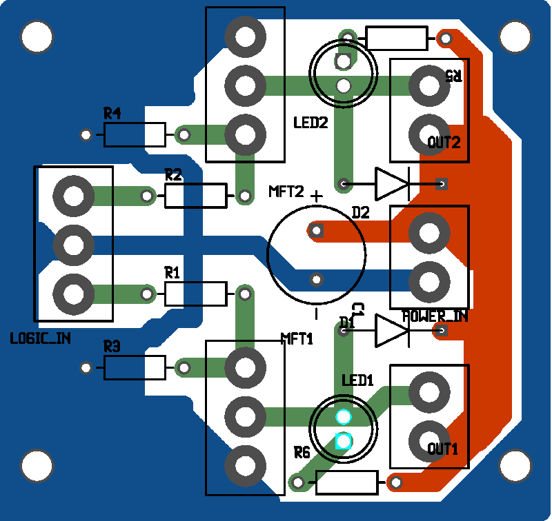
If so, from a more practical point of view, i would like to point out to situations like the red circles in the picture [www.reprap.org] and its fairly usual that the drill holes almost cut the traces they are onto. At which degree that can be regarded as an issue that remains to be decided for each individual, but i would rather put the traces slightly off-holes. For example the middle capacitor is alright while others are not so much.
I would aslo increase the track widths at least double or better triple than they are now (where possible make the traces as big as equal to the space between them). Stepper outputs imo look just slighlty bulky, the traces there i would make exactly as big as their pads and then minus only one increment.
However stuff like this is more like a "polishing" phase once the layout is pretty much decided on.
Another thing is i imagine at least some peoples could / would want to try this with their own different stepper boards then will have to takeout the signals (step, dir, enable, gnd etc) out to their board(s). So i would make some bigger pads around those so they can sustain repetitive soldering tasks (imo, best connector is solder joint). Or alternatively if not near the board steppers, then somewhere else on the tracks, (where convenient) at least a provision of a healthy, bulky, relatively clear area to take signals out from there.
On the general picture, this being almost single sided, at toner transfer i would make the bottom layer ground plane (mostly). Ofc microstripping wont reach the elevated stepper drivers where it could of been of some use, but it wont be bad either. The board design could go as much as rely on bottom as gnd plane and take out all gnd lines from top to simplify it, but that can be regarded as extreme and i cant say if clearing resulted on the top would be worth the effort, but maybe it is worth a shot to see how it comes up like - up to you ofc.
|
Re: Generation 7 Electronics Development December 03, 2010 07:59AM |
Registered: 13 years ago Posts: 7,616 |
Quote
i want to ask if the board is intended to be suitable for diy purposes.
Yes, being suitable for DIY and being reprappable is the whole purpose of this "Gen7" variant of electronics.
Quote
i would like to point out to situations like the red circles in the picture [www.reprap.org] and its fairly usual that the drill holes almost cut the traces they are onto. At which degree that can be regarded as an issue that remains to be decided for each individual, but i would rather put the traces slightly off-holes.
Another, more PCB-design-software compatible way would be to make the pads around such holes bigger. BTW., this picture doesn't show a Gen7 board, right?
Quote
However stuff like this is more like a "polishing" phase once the layout is pretty much decided on.

Quote
Another thing is i imagine at least some peoples could / would want to try this with their own different stepper boards then will have to takeout the signals (step, dir, enable, gnd etc) out to their board(s).
How about using a male connector (like it's packaged with the Pololu boards) and sticking that into the female connectors instead of these Pololus? If you don't have the males, solder an inch of copper wire to the tip of your flexible wire. Works just nicely here.
Quote
On the general picture, this being almost single sided, at toner transfer i would make the bottom layer ground plane (mostly). Ofc microstripping wont reach the elevated stepper drivers where it could of been of some use, but it wont be bad either. The board design could go as much as rely on bottom as gnd plane and take out all gnd lines from top to simplify it, but that can be regarded as extreme and i cant say if clearing resulted on the top would be worth the effort, but maybe it is worth a shot to see how it comes up like - up to you ofc.
Sure. Feel free to find a better tracing of the board. Particularly, I'm impressed by the tracing of the Repic board. Perhaps we can learn something here.
One question from my side: How did you get the board in your picture so nicely tinned?
| Generation 7 Electronics | Teacup Firmware | RepRap DIY |
|
Re: Generation 7 Electronics Development December 03, 2010 09:05AM |
Registered: 13 years ago Posts: 1,352 |
No, the picture with the hole in the trace is the 3.3v stepper driver board, shown on this page [www.reprap.org]. As off-topic, incidentally i also need some tuning help on the board in picture here [forums.reprap.org] I have tried 3 different motors on it, and while i found that getting them to run acceptable isnt really hard, but getting correct math values seems to be. I have some points where my theory results seems to have no clue to where reality is, so i guess i am making a few mistakes just cant seem to find the way out.
The tinning is simply done with a solder wick imbued with solder and passed over traces with a big iron, and as step 2 if it lays excessive solder, then a clean wick can be used to clean it up. Also alternatively without wick, with one of those big iron guns that use a thick copper wire as heated element, i had one wire like that brushed against a sand paper to flatten it a little, activate the tip, then putting only a small amount of solder and passing over the board gently. Needs just a little training so after a few boards it starts looking better and better. Prior use of SK-10 calofonia spray on board can help. Also there is a tinning chemical, but that is expensive stuff and also once prepared has a limited life, so i dont see any reason to use that.
+found a youtube vid for that kind of tinning here [www.youtube.com] and added it to the page, its sort of how i do it except right after removing the toner with acetone so copper is not oxidized thus no need to clean it, and i use one of those high power iron guns that resembles a pistol and has the wire as heated element instead, i find it much better for this job as it can cover bigger areas faster and easier
Back to on topic, most of time, doing some toner transfer boards in house, i find alot of pcb layouts to need some minor adjustments, most frequent being a hole cuts a trace (coz commercial ones are plated through so they dont care for that aspect), or a thin line comes off during some soldering on it or on a component that is on it (i suspect that depends on substrate too, i think fr4 fiber glass or w/e it is adhere differently to copper side than other substrates, but cant say for sure). Frequently i get myself into situations like "if i only have had done *that* before etching i wouldnt of had this trouble". So, having met situations like those i usually try to anticipate them beforehand when thinking of doing something. I guess in time that turned me into a little minor-changes obsessed dwarf so i could be exagerating a little
Edited 2 time(s). Last edit at 12/03/2010 09:22AM by NoobMan.
|
Re: Generation 7 Electronics Development December 04, 2010 04:39AM |
Registered: 14 years ago Posts: 458 |
Short question, is there any support on the board for thermocouples?
I can't tell in the photos if you do or don't, and this is a pretty important feature, if just for the extruder. Also, I will never use a thermistor for measuring the hearter barrel, unless it has a high temmperature rating and easily obtainable, which K type thermocouples are.
I can't tell in the photos if you do or don't, and this is a pretty important feature, if just for the extruder. Also, I will never use a thermistor for measuring the hearter barrel, unless it has a high temmperature rating and easily obtainable, which K type thermocouples are.
|
Re: Generation 7 Electronics Development December 04, 2010 06:21AM |
Registered: 13 years ago Posts: 7,616 |
Quote
Short question, is there any support on the board for thermocouples?
As far as I can see, you'd still need a Thermocouple Sensor Board. Looks like a worthwile addition, though.
| Generation 7 Electronics | Teacup Firmware | RepRap DIY |
|
Re: Generation 7 Electronics Development December 04, 2010 04:19PM |
Registered: 14 years ago Posts: 458 |
Traumflug Wrote:
-------------------------------------------------------
> Short question, is there any support on the board
> for thermocouples?
>
> As far as I can see, you'd still need a
> Thermocouple Sensor Board. Looks like a worthwile
> addition, though.
Yep, currently using this on my 3D printer, though there is also the use of the MAX6675 which interfaces over I2C
[reprap.org]
Makerbot electronics are supporting this in their next gen boards, yet to be released.
|
Re: Generation 7 Electronics Development December 05, 2010 07:58PM |
Registered: 13 years ago Posts: 228 |
NoobMan Wrote:
-------------------------------------------------------
> As i am a toner transfer noob, i want to ask if
> the board is intended to be suitable for diy
> purposes.
Certainly! As for my branch of mods, I am aiming to PCB routing of Voronoi regions rather than toner transfer. I just got a full proof (a couple of h-bridge boards) that this toolpath is working flawlessly, at least on Ubuntu 10.4 32 Bit: gEDA --> Gerber and Excellon files --> pcb2gcode --> emc2/axis --> tabletop router w/60 degrees & 0.2 mm engraving tip at 0.1 mm depth (still too deep!). The reults are excellent with a density equivalent to Gen7. Will post some details on the wiki page on pcb routing.
"Traces" obtained with Voronoi regions are "as wide as possible" and there are few issues with trace cutting.
> Another thing is i imagine at least some peoples
> could / would want to try this with their own
> different stepper boards then will have to takeout
> the signals (step, dir, enable, gnd etc) out to
> their board(s). So i would make some bigger pads
> around those so they can sustain repetitive
> soldering tasks (imo, best connector is solder
> joint). Or alternatively if not near the board
> steppers, then somewhere else on the tracks,
> (where convenient) at least a provision of a
> healthy, bulky, relatively clear area to take
> signals out from there.
They could be taken form the stepper driver connectors IMHO (would be a reasonable idea to socket them anyway)
About adding thermocouple support: good idea! does this require to set apart specific pins for I2C or can it be interfaced with any spare pins? (and maybe a daughterboard)?
L.
|
Re: Generation 7 Electronics Development December 06, 2010 01:43AM |
Registered: 14 years ago Posts: 458 |
|
Re: Generation 7 Electronics Development December 06, 2010 01:39PM |
Registered: 13 years ago Posts: 161 |
Hello,
I'm intrested in the Gen7 Electronics. I read the whole Thread and I have a couple of questions and suggestions:
* At the beginning of the thread there was a suggestion by someone to put 5 stepper motor drivers on the board for a second extruder, why was the idea discarded or did it just go down?
* There was also a suggestion to put all pins of the stepper motors on one port. It was discarded because it makes no difference for the motors. But what about the software? This could save some cpu cycles for each interrupt. Just 7 more cycles each interrupt can make a big difference.
* Am I right that the board will need a total new firmware? Is there alredy something done?
* Is the board in the current release already usable, if not, what is missing?
|
Re: Generation 7 Electronics Development December 06, 2010 07:38PM |
Registered: 13 years ago Posts: 228 |
Another suggestion - saw this in some electronics site, and indeed it does make sense: the MOSFETS should be mounted either on sockets or screw terminals (whatever you prefer), as they tend to burn/short out for many reasons closely related to tinkering/experimenting, and they need replacement. Better to factor in an easy way to change them,, the cost of the terminals/sockets is well under the cost of time spent de-soldering and re-soldering.
What do you think of opto-isolators, supposing one foresees driving a small spindle/inductive load ?
I like the idea of an optional 5th stepper driver too....
L.
What do you think of opto-isolators, supposing one foresees driving a small spindle/inductive load ?
I like the idea of an optional 5th stepper driver too....
L.
|
Re: Generation 7 Electronics Development December 07, 2010 05:52AM |
Registered: 13 years ago Posts: 7,616 |
Quote
* At the beginning of the thread there was a suggestion by someone to put 5 stepper motor drivers on the board for a second extruder, why was the idea discarded or did it just go down?
This would make the board bigger, that's the only reason.
Quote
* There was also a suggestion to put all pins of the stepper motors on one port. It was discarded because it makes no difference for the motors. But what about the software? This could save some cpu cycles for each interrupt. Just 7 more cycles each interrupt can make a big difference.
This wouldn't work at all, as you have to move motors individually to get any other movement than 45 deg movements. Perhaps I misunderstand the suggestion, though.
Quote
* Am I right that the board will need a total new firmware? Is there alredy something done?
Nope, same firmware as all the other boards.
Quote
* Is the board in the current release already usable, if not, what is missing?
Missing before it'll work at all:
- The clock crystal and the processor currently share the same space. Won't work in reality.
- The 5 V traces in the lower right are too thin.
- Same for ground traces in the lower left.
- The situation about 5 V (switchable) and 5V SB (always on) is unclear. Some sources claim you can run the processor off 5 V SB and all the others off 5 V. This would be great, as you could turn the power supply on an off with the processor. However, other sources talks about failure to do so.
Other things missing, but not essential:
- Get rid of the empty space near the center.
- Get an USB to Serial converter or direct USB onto the board. Currently an external converter is required. Problem: The drawbacks of direct USB are unclear (USB has tight timing demands) and there's obviously no USB2Serial chip with 2.54 mm pin spacing available.
- Move the 12 V connector from top right to top left to reduce currents flowing in the traces.
- Review Endstop connectors to be compatible with Gen3, Gen6, RAMPS or at least one of them.
- Add space at the side of the ATX-20 connector to allow ATX-24 PSUs as well.
- Add a wall wart connector and a 12 V to 5 V reducer to allow small power supplies instead of the ATX-20.
- Various other suggestions, like screw terminals for the FETs or thermocouple electronics on board.
| Generation 7 Electronics | Teacup Firmware | RepRap DIY |
|
Re: Generation 7 Electronics Development December 07, 2010 12:27PM |
Registered: 13 years ago Posts: 91 |
> - Get an USB to Serial converter or direct USB
> onto the board. Currently an external converter is
> required. Problem: The drawbacks of direct USB are
> unclear (USB has tight timing demands) and there's
> obviously no USB2Serial chip with 2.54 mm pin
> spacing available.
How about a second processor programmed as a USB-serial converter? This could be a second AVR with V-USB, or a PIC18 or 24 with hardware USB. The PIC24 can also host (printing from USB stick?).
|
Re: Generation 7 Electronics Development December 07, 2010 08:05PM |
Registered: 13 years ago Posts: 64 |
Traumflug Wrote:
-------------------------------------------------------
> * There was also a suggestion to put all pins of
> the stepper motors on one port. It was discarded
> because it makes no difference for the motors. But
> what about the software? This could save some cpu
> cycles for each interrupt. Just 7 more cycles each
> interrupt can make a big difference.
>
> This wouldn't work at all, as you have to move
> motors individually to get any other movement than
> 45 deg movements. Perhaps I misunderstand the
> suggestion, though.
When the firmware is running the Bresenham to do the move the fastest axis is a master and the others are stepped when they need to be in time with that master. So a tick of the movement interrupt might be one stepper or all of the steppers depending on the algorithm and it is guaranteed that if more than one axis is moving there will be interrupts where more than one axis is stepped at the same time. Having all the STEP pins on the same port allows any steppers that need to be stepped in that interrupt use less micro controller instructions and at the exact same time (that would only matter in making an exactly perfect 45). Being on the same port doesn't mean they have to step at the same time, but can be if desired.
|
Re: Generation 7 Electronics Development December 07, 2010 10:27PM |
Registered: 16 years ago Posts: 1,094 |
Traumflug Wrote:
-------------------------------------------------------
> - The situation about 5 V (switchable) and 5V SB
> (always on) is unclear. Some sources claim you can
> run the processor off 5 V SB and all the others
> off 5 V. This would be great, as you could turn
> the power supply on an off with the processor.
> However, other sources talks about failure to do
> so.
That source points out a manufacturing error whereby reset was pulled "up" to 5V instead of 5Vsb so the processor stayed in reset until the power supply turns on, a catch-22 condition.
My electronics run the atmega from 5Vsb and everything else from 12v, with the chip turning the psu on and off as necessary. I regulate the 12v down to 5v onboard to mitigate noise issues, and load the 5v line to prop up the 12v current capability. It works great, and allows software emergency shutdown of motors, heaters, etc in the case that it detects a shorted mosfet or something.
-----------------------------------------------
Wooden Mendel
Teacup Firmware
|
Re: Generation 7 Electronics Development December 08, 2010 05:05AM |
Registered: 13 years ago Posts: 7,616 |
Quote
How about a second processor programmed as a USB-serial converter?
Quite possible. I guess I'll have to actually try ;-)
Quote
When the firmware is running the Bresenham to do the move the fastest axis is a master and the others are stepped when they need to be in time with that master. So a tick of the movement interrupt might be one stepper or all of the steppers depending on the algorithm and it is guaranteed that if more than one axis is moving there will be interrupts where more than one axis is stepped at the same time. Having all the STEP pins on the same port allows any steppers that need to be stepped in that interrupt use less micro controller instructions and at the exact same time (that would only matter in making an exactly perfect 45). Being on the same port doesn't mean they have to step at the same time, but can be if desired.
Yes, this logic sounds good and reasonable. However I can't see how one would "select" a stepper driver to do a step or not, unless they're on different ports. These drivers have only two relevant pins: STEP: "do a step now" and DIR: "do it normal vs. do it reversed". There's also an ENABLE pin (not connected in Gen7), but this one turns off the entire logic and motor currents, with the potential to loose the axis position.
Triffid, thanks for the explanation. Now that stuff makes sense :-)
| Generation 7 Electronics | Teacup Firmware | RepRap DIY |
|
Re: Generation 7 Electronics Development December 08, 2010 12:09PM |
Registered: 14 years ago Posts: 30 |
[www.recursion.jp]
The attiny45 version of v-usb would work nicely as a usb-serial, as long as we dont need a higher baud than 4800bps. 8 pin micro, 5 resistors, led, capacitor. All breadboardable too.
The attiny45 version of v-usb would work nicely as a usb-serial, as long as we dont need a higher baud than 4800bps. 8 pin micro, 5 resistors, led, capacitor. All breadboardable too.
|
Re: Generation 7 Electronics Development December 08, 2010 10:49PM |
Registered: 13 years ago Posts: 7,616 |
For the records, I've compared Opto Endstop connectors of all boards I could find in the Wiki. Here's the summary:
3 pin 5V - Signal - GND: Gen2, Gen3, "Pololu Electronics"
3 pin Signal - GND - 5V: RAMPS
Mechanical switches only: Ultimaker 1.1, UltiMaker 1.3
All 5 wires of the opto: Gen6
As the Gen2 layout isn't ideal for single sided boards, I've changed Gen7's to match those of RAMPS.
Hmm. After that having done I've found all the pictures Lanthan has uploaded. No idea how I managed to miss that so far. Nice work! Don't forget to move the temperature inputs back to the PA... ports.
| Generation 7 Electronics | Teacup Firmware | RepRap DIY |
|
Re: Generation 7 Electronics Development December 09, 2010 12:08AM |
Registered: 13 years ago Posts: 64 |
Traumflug Wrote:
-------------------------------------------------------
> Yes, this logic sounds good and reasonable.
> However I can't see how one would "select" a
> stepper driver to do a step or not, unless they're
> on different ports. These drivers have only two
> relevant pins: STEP: "do a step now" and DIR: "do
> it normal vs. do it reversed". There's also an
> ENABLE pin (not connected in Gen7), but this one
> turns off the entire logic and motor currents,
> with the potential to loose the axis position.
I think you have a misunderstanding of what a PORT is in the AVR. A PORT is a collection of 8 bits with each bit being an output pin. Internally the AVR ties 8 pins into a PORT and the software sets bit in that PORT to turn on any of the pins. An instruction to turn on a pin sets a bit mask on the PORT which enables it. That mask could be one bit or more than one causing more than one pin to go high at the same time.
|
Re: Generation 7 Electronics Development December 09, 2010 09:35AM |
Registered: 13 years ago Posts: 7,616 |
jv,
that makes some sense. You want all DIR pins of the steppers on one 8 bit port, so the firmware can AND the bits together before setting them, instead of setting them one by one.
that makes some sense. You want all DIR pins of the steppers on one 8 bit port, so the firmware can AND the bits together before setting them, instead of setting them one by one.
| Generation 7 Electronics | Teacup Firmware | RepRap DIY |
|
Re: Generation 7 Electronics Development December 09, 2010 03:08PM |
Registered: 13 years ago Posts: 161 |
Traumflug Wrote:
-------------------------------------------------------
> * Am I right that the board will need a total new
> firmware? Is there alredy something done?
>
> Nope, same firmware as all the other boards.
Ohh my god, do I have to use the Adruino software again? I hate it!
And I downloaded the pcb and opended it. I have to say that this program is totally new to me but why do I get about more than 80 design rule errors?
|
Re: Generation 7 Electronics Development December 09, 2010 04:53PM |
Registered: 13 years ago Posts: 7,616 |
Quote
do I have to use the Adruino software again?
FiveD on Arduino comes with traditional makefiles and this Arduino thingy allows to use an external text editor. Having the IDE installed comes in handy, though, as it comes with all the required compilers and helper applications.
Quote
why do I get about more than 80 design rule errors?
If you have fixed them, I'll happily upload the results. Keep in mind, though, neither the good part of Lanthans great bunch of changes nor the fixes for the shortcomings mentioned a few posts above are uploaded (or even created), yet.
| Generation 7 Electronics | Teacup Firmware | RepRap DIY |
|
Re: Generation 7 Electronics Development December 09, 2010 08:24PM |
Registered: 13 years ago Posts: 64 |
Traumflug Wrote:
-------------------------------------------------------
> jv,
>
> that makes some sense. You want all DIR pins of
> the steppers on one 8 bit port, so the firmware
> can AND the bits together before setting them,
> instead of setting them one by one.
The STEP pins are the important ones to me. Having DIR all on one PORT would be a bonus. I think the DIR only get set at the start of the move so the overhead is minimal from separate sets.
|
Re: Generation 7 Electronics Development December 12, 2010 03:35PM |
Registered: 13 years ago Posts: 161 |
Traumflug Wrote:
-------------------------------------------------------
> If you have fixed them, I'll happily upload the
> results. Keep in mind, though, neither the good
> part of Lanthans great bunch of changes nor the
> fixes for the shortcomings mentioned a few posts
> above are uploaded (or even created), yet.
I'll work on it but I don't know when I will have time for that. We are having trouble with our nozzle and this has priority But I will stay tuned because when we finished printing the Mendel parts the first Mendel will NOT use the gen 3 electronics
-------------------------------------------------------
> If you have fixed them, I'll happily upload the
> results. Keep in mind, though, neither the good
> part of Lanthans great bunch of changes nor the
> fixes for the shortcomings mentioned a few posts
> above are uploaded (or even created), yet.
I'll work on it but I don't know when I will have time for that. We are having trouble with our nozzle and this has priority
But I will stay tuned because when we finished printing the Mendel parts the first Mendel will NOT use the gen 3 electronics
|
Re: Generation 7 Electronics Development December 13, 2010 03:42PM |
Registered: 13 years ago Posts: 33 |
I'm really keen to make my own pcb but Gen3 does not lend itself to home production (vias are too small to drill and put wire through).
Gen 7 seems ideal for this (I'd still prefer SMT resistors as it saves drilling heaps of holes). The only problem I have is I can't open the files on windows? (I know I could start using Linux but that's a whole different learning curve I don't' have time for).
Could someone extract the copper layer and post it somewhere?
Has someone duplicated this in Eagle?
|
Re: Generation 7 Electronics Development December 13, 2010 06:46PM |
Registered: 13 years ago Posts: 228 |
Some thoughts about MOSFETS
I recently completed a milled pcb with the exact same MOSFETS circuit extracted from gen7 (my interpretation "gen 7 simplified", posted some time ago in this thread). I was able to verify it is working perfectly with arduino hardware PWM at 32 KHz (Timer1 library). Intention is to drive a small spindle.
Wondering if:
1) Might be a good idea to move those MOSFETS to a separate board after all. This would reduce clutter and dimensions of the motherboard. Added benefit: we could even select different voltages for different uses (example: the particular spindle motor I am using tops up at 27V)
2) Does anybody know about an equivalent of the Timer1 library for the Sanguino? Is it easily portable? Turns out it is a boon to configure PWM cycles with that.
Comments, ideas?
L.
I recently completed a milled pcb with the exact same MOSFETS circuit extracted from gen7 (my interpretation "gen 7 simplified", posted some time ago in this thread). I was able to verify it is working perfectly with arduino hardware PWM at 32 KHz (Timer1 library). Intention is to drive a small spindle.
Wondering if:
1) Might be a good idea to move those MOSFETS to a separate board after all. This would reduce clutter and dimensions of the motherboard. Added benefit: we could even select different voltages for different uses (example: the particular spindle motor I am using tops up at 27V)

2) Does anybody know about an equivalent of the Timer1 library for the Sanguino? Is it easily portable? Turns out it is a boon to configure PWM cycles with that.
Comments, ideas?
L.
|
Re: Generation 7 Electronics Development December 14, 2010 05:39AM |
Registered: 13 years ago Posts: 7,616 |
Quote
korban
The only problem I have is I can't open the files on windows?
There's a Windows build:
[www2.eng.cam.ac.uk]
Quote
Could someone extract the copper layer and post it somewhere?
Doesn't make sense as of today, as there are still a few issues to be fixed. So you have to waste your time waiting instead of learning a useful OS, unfortunately.
Quote
Lanthan
Does anybody know about an equivalent of the Timer1 library for the Sanguino?
Hmm. What's the Timer1 library, what's wrong with it and to where do you want to port it?
| Generation 7 Electronics | Teacup Firmware | RepRap DIY |
|
Re: Generation 7 Electronics Development December 14, 2010 06:26AM |
Registered: 13 years ago Posts: 228 |
To Korban: yes, any time invested learning un*xes is time well spent and finally pays off wonderfully.
Me:
>
> Does anybody know about an equivalent of the
> Timer1 library for the Sanguino?
Traumflug:
>
> Hmm. What's the Timer1 library, what's wrong with
> it and to where do you want to port it?
Timer1 library for arduino (atmega168, atmega328) http://www.arduino.cc/playground/Code/Timer1 , provides an unobtrusive interface to manipulate, well, timer 1 (arduino pins 9 and 10) settings, such as PWM cycle, attach interrupts etc.
I am currently testing stuff with an arduino. I was looking for something to modify the default PWM cycle setting for Timer1 (about 500 Hz) to about 32 KHz. This will come useful when pwm-driving a small spindle DC motor with the mentioned MOSFETS, and as implemented in the library, is a fire-and-forget operation.
#include "TimerOne.h"
const int ledPin = 10; // LED connected to digital pin 10
const int potPin = 5; // Potentiometer connected to analog pin 5
int potval = 0 ; // store value of pot here
void setup() {
Serial.begin(9600); // init serial comm
Timer1.initialize(30); // initialize timer1, and set period to 30 microseconds
Timer1.pwm(ledPin,0) ; // initialize PWM on pin 10 with duty cycle 0
}
void loop() {
int potval = analogRead(potPin); // read pot
Serial.println(potval) ;
Timer1.setPwmDuty(ledPin, potval) ;
// wait for x milliseconds
delay(10);
}
I agree this does not make any sense if you just want to drive a couple of heater resistors, but should you ever want to do some light milling with Gen7 electronics and some sturdy reprap design, you'd find uses to higher PWM frequencies.
Yes this can also be done by directly and-ing / or-ing some registers, but in a more involved way (IMHO).
So I went looking for more information on Sanguino / atmega644 pins ports and timers, but of course there is less documentation floating around, as compared to the Arduino. Probably I haven't looked around hard enough.
L.
|
Re: Generation 7 Electronics Development December 14, 2010 08:09AM |
Registered: 13 years ago Posts: 1,352 |
About usb to serial, how about ATMega8U2 as in the new arduino uno and mega
5th stepper board: as there some peoples discovered a new feasable way to dissolve PLA and make use of it as support material, this could be of more use in the future than previously thought
@Lanthan: double sided milling a board - how is it done, is it complicated, is the margin of error too big? i dont have any pcb milling experience, i honestly prefer double sided toner transfer which i find pretty simple and easy, most of times seems easier than single sided versions which have alot of complications and usually take more space
@Korban: Gen3 pcbs can be made in home, although a lot of patience and good tools are needed, some files are here [www.thingiverse.com] let me know what u think of those


Sorry, only registered users may post in this forum.