Generation 7 Electronics Development
Posted by Traumflug
|
Re: Generation 7 Electronics Development December 14, 2010 08:20AM |
Admin Registered: 16 years ago Posts: 13,884 |
... doublesided milling can be really accurate with symmetric fitting holes, so you'll mill and drill the first side, insert fitting pins in the holes, flip the PCB, place it on the fitting pins and mill the second side.
I'm milling double-sided PCB's with finepitch SMT'pads on my old mill (specified with 12.5 microns accuracy) and can achieve around 20 microns accuracy with this methode ...
Viktor
--------
Aufruf zum Projekt "Müll-freie Meere" - [reprap.org] -- Deutsche Facebook-Gruppe - [www.facebook.com]
Call for the project "garbage-free seas" - [reprap.org]
|
Re: Generation 7 Electronics Development December 14, 2010 08:55AM |
Registered: 13 years ago Posts: 1,352 |
I find myself also double sided toner transfer very easy.
Then why do we bother with single sided issues when double sided has plenty of advantages. Is it worth the complications?
Advantages: can get smaller traces lengths, more compact component population, smaller form factor
Disadvantages: making some vias (no. of vias can be minimized); eventual increase in milling time (not significant etching time)
At the distances and pitches of this board, double side as DIY is a walk in the park imo - but may be just me.
Edited 1 time(s). Last edit at 12/14/2010 08:58AM by NoobMan.
|
Re: Generation 7 Electronics Development December 14, 2010 09:14AM |
Admin Registered: 16 years ago Posts: 13,884 |
... if you have all tools and materials for etching at hand, it's easier than milling - i had professional equipment for exposing and etching PCB's until size of 300x200mm, but gave it all away in exchanging for other tools, as with my occasional projects the chemicals thend to clogg and outdate ...
Now either i'll mill them or order in PCB-pools, if i need bigger series or really complex or multilayer-boards ...
By the way - if using thinner doublesided material you can laminate two or three boards with presoldered through-vias, so even 4- or 6-layer-PCB's are possible with DIY-methods
Viktor
--------
Aufruf zum Projekt "Müll-freie Meere" - [reprap.org] -- Deutsche Facebook-Gruppe - [www.facebook.com]
Call for the project "garbage-free seas" - [reprap.org]
|
Re: Generation 7 Electronics Development December 14, 2010 09:54AM |
Registered: 13 years ago Posts: 1,352 |
Its extremely tedious process but can be done. But that stuff ends up like being from 60's and pretty much looks ugly  .
.
Can make 4-6 layer using '100 cutted single pins between as vias. Internal part needs to be done first, rather in lead free. Making 4 layer is easier with 2 single sided and one double side in between. With 3x double sided, the issue is the back side of the exterior boards which dont have access. Can predeposit alot of solder near the back sides so when the pin is heated, it fuses to internal layers that are no longer accessible. Even if the holes are a little bigger can help making the solder flow trough hole. I couldnt figure other technique to ensure good connections inside layers where there is no access.
I have been looking around for a way to DIY electroplating through hole in house, doable with just a lab supply source, but havent found a good and cheap hole wall activator, which is the key for it, and all are very expensive, so its stuck on my to do list for a while.
.Can make 4-6 layer using '100 cutted single pins between as vias. Internal part needs to be done first, rather in lead free. Making 4 layer is easier with 2 single sided and one double side in between. With 3x double sided, the issue is the back side of the exterior boards which dont have access. Can predeposit alot of solder near the back sides so when the pin is heated, it fuses to internal layers that are no longer accessible. Even if the holes are a little bigger can help making the solder flow trough hole. I couldnt figure other technique to ensure good connections inside layers where there is no access.
I have been looking around for a way to DIY electroplating through hole in house, doable with just a lab supply source, but havent found a good and cheap hole wall activator, which is the key for it, and all are very expensive, so its stuck on my to do list for a while.
|
Re: Generation 7 Electronics Development December 14, 2010 02:19PM |
Registered: 13 years ago Posts: 228 |
NoobMan Wrote:
> @Lanthan: double sided milling a board - how is it
> done, is it complicated, is the margin of error
> too big?
Usually ppl use symmetric register pins, as has ben pointed out.
Personally I haven't yet tried it, but I see no major problems.
I'm on my second milled project, just posted pics of the first in the wiki (pcb milling) at the very end of the page.
It is coming out nice and clean, and can be done quite accurately with simple means (haven't even cared to mill down the sacrificial board yet).
At least I have all of the toolchain from gEDA to the finished board tested and working.
> i dont have any pcb milling experience, i
> honestly prefer double sided toner transfer which
> i find pretty simple and easy,
Excepted for the nasty chemicals to store and to dispose of, and it does not deal with drilling holes.
I guess this is a question of mindset too. But if you can get your hands on even a half-good CNC engraver, try it, you'll like it ;-)
> most of times seems
> easier than single sided versions which have alot
> of complications and usually take more space
Certainly. Another possibility is to stack stuff, shield-like. Allows for modularity. I'm toying with this idea for my future board...
L.
|
Re: Generation 7 Electronics Development December 14, 2010 05:33PM |
Registered: 13 years ago Posts: 33 |
@Noobman Thanks for that, I found your page : DIY PCB
I etched the Motherboard v1.2 last night using transparencies and UV exposure technique. I can usually get 5mil clearances and 6mil tracks. I really struggled with the vias tho, the smallest drill bit I could find was 0.8mm which was a little big for the vias. The vias under the micro are a bit questionable, not sure if the micro will sit on top ok, will see when it turns up.
Next I need to sort a way to program it
|
Re: Generation 7 Electronics Development December 14, 2010 06:37PM |
Registered: 13 years ago Posts: 1,352 |
I guess i will have to open my head to pcb milling.
Although i am more like traditionalist in the sens of "shortest way is the one i know".
I am working on a stiffer cnc router -eta in the spring- and i should certainly test pcb milling on it then.
Thanks for the push on that direction, i dont think i would of gone for it otherwise.
Edit @Korban: for via 0.5mm is good, but 0.8 should work too; the vias under micro can be grinded down with a dremel like in the picture there; best wire i found is a thin wire like argintated wire here [www.metrafo.ro] its normally used in special pistols for wire-to-wire links, dont know how to call the stuff exactly in english and not everybody sells this wire either, but otherwise other wires should work too; good luck btw
Edited 1 time(s). Last edit at 12/14/2010 06:44PM by NoobMan.
|
Re: Generation 7 Electronics Development December 14, 2010 07:28PM |
Registered: 13 years ago Posts: 228 |
NoobMan Wrote:
-------------------------------------------------------
> I guess i will have to open my head to pcb
> milling.
> Although i am more like traditionalist in the sens
> of "shortest way is the one i know".
> I am working on a stiffer cnc router -eta in the
> spring- and i should certainly test pcb milling on
> it then.
>
> Thanks for the push on that direction, i dont
> think i would of gone for it otherwise.
Once you have it you start seeing lots of things "cnceable" ;-)
I released the gEDA files for the small MOSFET breakout (plus a couple of new pictures) here:
http://www.thingiverse.com/thing:5151
|
Re: Generation 7 Electronics Development December 15, 2010 01:02PM |
Registered: 13 years ago Posts: 161 |
|
Re: Generation 7 Electronics Development December 15, 2010 06:11PM |
Registered: 13 years ago Posts: 1,352 |
Jacky2k Wrote:
-------------------------------------------------------
> @Korba: About which generation electronics are you
> talking?
> Somewhere I have a remake (selfmade) of the Gen3
> with Vias sized at least 0,8mm and no via under
> any component. Just this way we were able to make
> the pcb our own.
Is it possible to upload it to thingverse? or to edit this page here and add it at the end or anywhere u like [www.reprap.org]
|
Re: Generation 7 Electronics Development December 16, 2010 12:19PM |
Registered: 13 years ago Posts: 161 |
NoobMan Wrote:
-------------------------------------------------------
> About usb to serial, how about ATMega8U2 as in the
> new arduino uno and mega
I had this idea some days ago, but is there a version in DIP? I think the ATMega8U2 is only in TQFP available.
One more idea: What about a general socket for this problem where you can plug any pcb you want which has to convert usb to uart or converts the uart to rs232/.... and has a plug for this. Then we will be able to create multiple boards for that with all these suggested solutions. I would prefer a FT232, someone else will use RS232 or a ATTiny with libusb.
I am also panning to use the IGEPv2 Board (something like BeagleBoard) to control the RepRap, so I will just need uart for that, no conversation. Fot that I just need a cable, no conversation.
Edited 4 time(s). Last edit at 12/16/2010 12:27PM by Jacky2k.
|
Re: Generation 7 Electronics Development December 17, 2010 04:56PM |
Admin Registered: 16 years ago Posts: 13,884 |
Hi Noobman,
... i've used hollow rivets as through-vias for complicated PCB's or multilayer-prototypes - here my vendor in Germany: [www.reichelt.de]
I've inserted the rivets from the side i wouldn't have acces later and soldered the collar only to the pad on this side, then inserted the components, flipped the PCB and soldered the pins of the components with the rivet together to the pad.
This will be the same for multilayer - the collars are then presoldered to the inner sides and the tubes reaches to the outside, where they can be soldered to the outer pads and/or the pins of the populated components ...
Edited 1 time(s). Last edit at 12/17/2010 05:00PM by VDX.
Viktor
--------
Aufruf zum Projekt "Müll-freie Meere" - [reprap.org] -- Deutsche Facebook-Gruppe - [www.facebook.com]
Call for the project "garbage-free seas" - [reprap.org]
|
Re: Generation 7 Electronics Development December 18, 2010 06:58PM |
Registered: 14 years ago Posts: 30 |
|
Re: Generation 7 Electronics Development December 19, 2010 06:14PM |
Registered: 13 years ago Posts: 7,616 |
With the great and big help of Jacky2k, Generation 7 Electronics has now addressed all known bugs and todo-lists. We'll know how well it works soon, as he has already etched a board. Thanks, Jacky2k.
While the first prototype was etched, the design still allows milling. A jumper was added to allow for non-PC power supplies without dropping support for PC-PSUs including software PSU-on-off. Still no USB, but all components are verified to be available and track widths should be sufficient in the high current parts. A number of noise reduction capacities were added to the power supply lines and a RC filter to the analog input reference voltage (see ATmega644P reference, page 250). Also an I2C header for those who can make use of it. Enjoy!
All files are available at the Generation 7 Electronics Github Repository, as always.
| Generation 7 Electronics | Teacup Firmware | RepRap DIY |
|
Re: Generation 7 Electronics Development December 20, 2010 07:49AM |
Registered: 14 years ago Posts: 30 |
|
Re: Generation 7 Electronics Development December 20, 2010 05:17PM |
Registered: 13 years ago Posts: 161 |
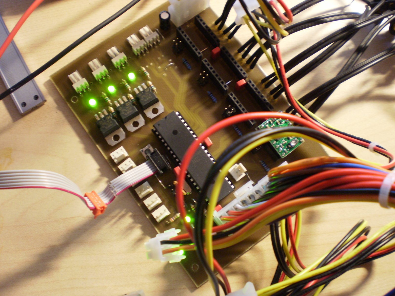
Jea when you use the 20pin ATX you have to use the 4 pin Molex. But you can use the 4 pin alone without the 20 pin atx connector. The fact that the 12V are not connected to the ATX conenctor has a simple reason: So it's possible to drive the motors with more than 12V threw the 4 pin molex. The pololu boards have a constant current driver, so you can use 24V or even more for better motor performance.
Here are the first picutures of the board.
Here are the first picutures of the board.
|
Re: Generation 7 Electronics Development December 22, 2010 12:37PM |
|
Re: Generation 7 Electronics Development December 22, 2010 05:09PM |
Registered: 13 years ago Posts: 5 |
This may be a silly question, but why hasn't anyone securely attached a fine point sharpie or resistive ink pen to their printer and used it to draw the PCB artwork on a piece of copper clad? Then all you have to do is dunk it (etch) and you've effectively printed the PCB form your Mendel.
|
Re: Generation 7 Electronics Development December 22, 2010 05:46PM |
Admin Registered: 17 years ago Posts: 7,879 |
|
Re: Generation 7 Electronics Development December 24, 2010 06:18AM |
Registered: 13 years ago Posts: 161 |
Bonz099 Wrote:
-------------------------------------------------------
> Board looks really great, any pics of the bottom
> side, or of it hooked all up? Have you tested it
> yet?
>
> Im so close to pulling the trigger on this, i just
> need to see it working just like the gen6 does and
> im game.
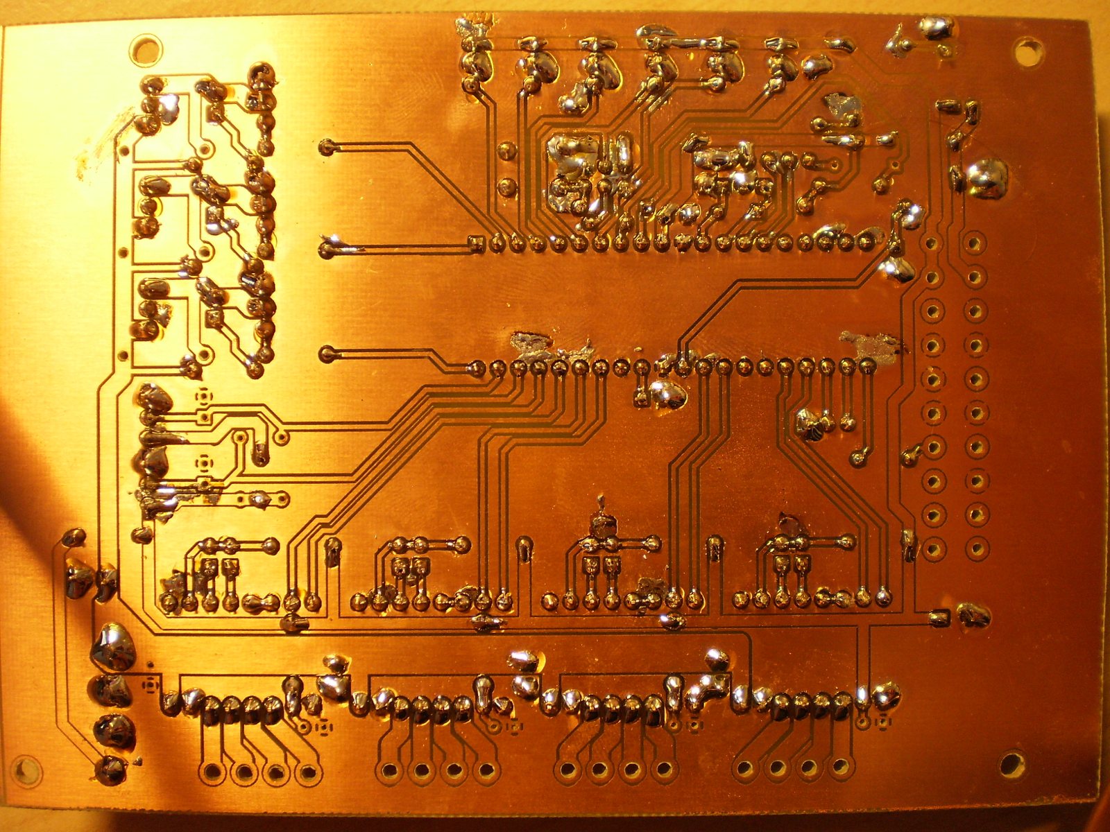
I am a little bit shamed of it. It looks damnable because the isolation distance of the auto ground was to less, so I hat many many problems with the soldering. And it is not tested yet. I'll do this in the next few days. I Hope that someone could help me with that, because I have no idea of Adroino or the firmware itself.
Edit: Forgot the picture
Edited 1 time(s). Last edit at 12/24/2010 06:20AM by Jacky2k.
-------------------------------------------------------
> Board looks really great, any pics of the bottom
> side, or of it hooked all up? Have you tested it
> yet?
>
> Im so close to pulling the trigger on this, i just
> need to see it working just like the gen6 does and
> im game.
I am a little bit shamed of it. It looks damnable because the isolation distance of the auto ground was to less, so I hat many many problems with the soldering. And it is not tested yet. I'll do this in the next few days. I Hope that someone could help me with that, because I have no idea of Adroino or the firmware itself.
Edit: Forgot the picture
Edited 1 time(s). Last edit at 12/24/2010 06:20AM by Jacky2k.
|
Re: Generation 7 Electronics Development December 24, 2010 09:45AM |
Registered: 13 years ago Posts: 5 |
What technique did you use to etch that board? Toner Transfer? Or UV Exposure? Either way it looks like it came out really great.
I would make some changes though, at least change the layout rules to allow for a larger tolerance between the plane and other pins. And possibly increase the trace distances form each other where ever possible to facilitate with the home fabrication methods for those less skilled or less experienced in board creation.
All and all, looks great, lemme know when you've tested it!
|
Re: Generation 7 Electronics Development December 24, 2010 10:26AM |
Registered: 13 years ago Posts: 161 |
Bonz099 Wrote:
-------------------------------------------------------
> What technique did you use to etch that board?
> Toner Transfer? Or UV Exposure? Either way it
> looks like it came out really great.
UV Exposure. The one and only method
As far as I know the layout rules cannot be made less strict because this board is design to be drilled with the RepRap.
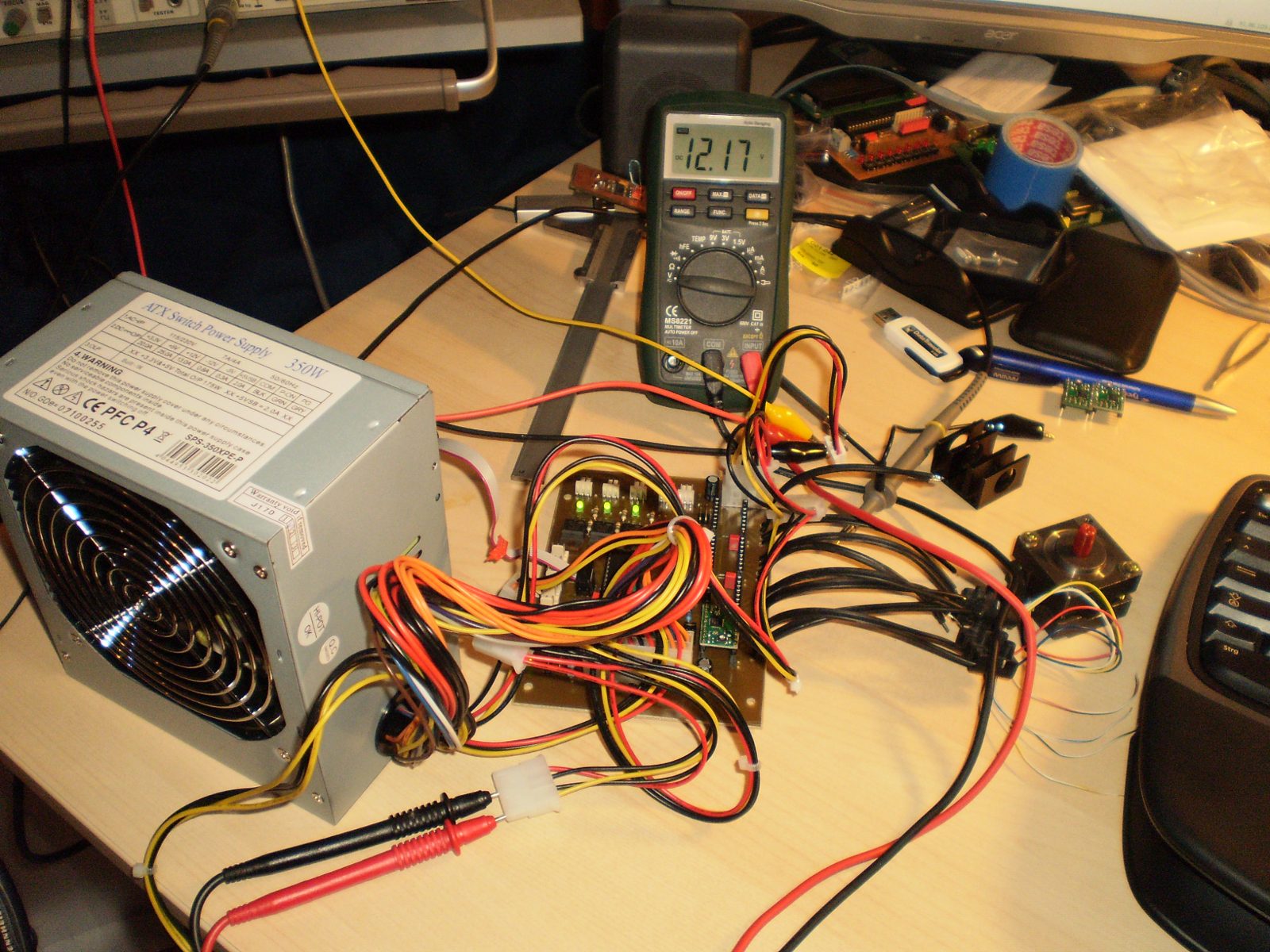
I've tested the board with a small test application software, everything seems to work fine without the ATX power supply. I get no 12V from it. Yes, I pulled down the PS ON Line and it is realy down and I am pulling about 1A out of the 5V line. Still no 12V available.
Edit: Found it! I forgot to remove the jumper at the left bottom of the board
Edited 1 time(s). Last edit at 12/24/2010 10:30AM by Jacky2k.
-------------------------------------------------------
> What technique did you use to etch that board?
> Toner Transfer? Or UV Exposure? Either way it
> looks like it came out really great.
UV Exposure. The one and only method
As far as I know the layout rules cannot be made less strict because this board is design to be drilled with the RepRap.
I've tested the board with a small test application software, everything seems to work fine without the ATX power supply. I get no 12V from it. Yes, I pulled down the PS ON Line and it is realy down and I am pulling about 1A out of the 5V line. Still no 12V available.
Edit: Found it! I forgot to remove the jumper at the left bottom of the board
Edited 1 time(s). Last edit at 12/24/2010 10:30AM by Jacky2k.
|
Re: Generation 7 Electronics Development December 24, 2010 10:45AM |
Registered: 13 years ago Posts: 5 |
|
Re: Generation 7 Electronics Development December 24, 2010 11:01AM |
Registered: 13 years ago Posts: 161 |
|
Re: Generation 7 Electronics Development December 24, 2010 02:37PM |
Registered: 13 years ago Posts: 5 |
Jacky2k Wrote:
-------------------------------------------------------
> [reprap.org]
>
> Here are some pictures of the working board (no
> RepRap software on it, yet).
Looks great!
-------------------------------------------------------
> [reprap.org]
>
> Here are some pictures of the working board (no
> RepRap software on it, yet).
Looks great!
|
Re: Generation 7 Electronics Development December 25, 2010 01:01PM |
Registered: 13 years ago Posts: 161 |
|
Re: Generation 7 Electronics Development December 27, 2010 09:42AM |
Registered: 13 years ago Posts: 161 |
|
Re: Generation 7 Electronics Development December 27, 2010 11:37AM |
Registered: 13 years ago Posts: 161 |
OK two fixes are required that the temperature is read and trasmitted:
In config.h set REFERENCE to REFERENCE_AVCC.
In temp.c in line 150 (may varay because I changed a lot) inside the function temp_read() is something like this:
Change it to this:
Then the temperature value is send over serial but the host software doesn't recognize it.
The format is this as an example:
In config.h set REFERENCE to REFERENCE_AVCC.
In temp.c in line 150 (may varay because I changed a lot) inside the function temp_read() is something like this:
	//Clamp for overflows
	if (i == NUMTEMPS)
		temp = temptable[NUMTEMPS-1][1];

	return temp;
Change it to this:
	//Clamp for overflows
	if (i == NUMTEMPS)
		temp = temptable[NUMTEMPS-1][1];
	current_temp = temp;
	return temp;
Then the temperature value is send over serial but the host software doesn't recognize it.
The format is this as an example:
T: 17.50\nAnd I also tryed the old one:
T: 18.75/190.0 :0\n
|
Re: Generation 7 Electronics Development December 27, 2010 11:53AM |
Registered: 13 years ago Posts: 161 |
|
Re: Generation 7 Electronics Development December 27, 2010 01:08PM |
Registered: 13 years ago Posts: 161 |


Sorry, only registered users may post in this forum.