Generation 7 Electronics Development
Posted by Traumflug
|
Re: Generation 7 Electronics Development December 27, 2010 02:36PM |
Registered: 13 years ago Posts: 161 |
|
Re: Generation 7 Electronics Development December 29, 2010 11:37AM |
Registered: 13 years ago Posts: 161 |
OK guys,
last night I have been working till 4 o'clock with two colleagues to get the RepStrap running and we had a lot of problems but solved all of them (at least all known problems).
There are some fixes required in the firmware to support endstops and homing.
I just wrote a patch instruction file and waiting for predatorian to test it. When it works, I'll post it here.
|
Re: Generation 7 Electronics Development December 29, 2010 01:13PM |
Registered: 13 years ago Posts: 161 |
|
Re: Generation 7 Electronics Development January 03, 2011 09:39AM |
Registered: 13 years ago Posts: 5 |

|
Re: Generation 7 Electronics Development January 03, 2011 12:24PM |
Registered: 13 years ago Posts: 161 |
We are still having VERY strange problems with the firmware. It is not stable yet!
The RepStrap is driving into the endstops, he stops sometimes for some seconds without any reason and continues like nothing happened, some object were cut into two peaces and placed wrong.
Seems like there is much to be done... we will stay tuned.
The RepStrap is driving into the endstops, he stops sometimes for some seconds without any reason and continues like nothing happened, some object were cut into two peaces and placed wrong.
Seems like there is much to be done... we will stay tuned.
|
Re: Generation 7 Electronics Development January 04, 2011 03:15PM |
Registered: 13 years ago Posts: 161 |

|
Re: Generation 7 Electronics Development January 05, 2011 03:11PM |
Registered: 13 years ago Posts: 161 |
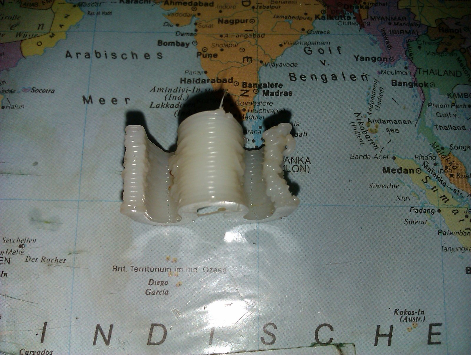
We made some firmware patches and I uploaded the current version to the wiki and attached it to this post.
We printed our first part with this hardware and firmware, it doesn't look so great as I said yesterday but it look like a printed part I attached a picture. We don't know why he makes the object that bad on the right side. Any idea? Software or hardware problem?
We printed our first part with this hardware and firmware, it doesn't look so great as I said yesterday but it look like a printed part
I attached a picture. We don't know why he makes the object that bad on the right side. Any idea? Software or hardware problem?
|
Re: Generation 7 Electronics Development January 05, 2011 05:26PM |
Admin Registered: 17 years ago Posts: 7,879 |
My guess is that is where is starts the outline on each layer. I.e. where extruder start and stop timings matter.
[www.hydraraptor.blogspot.com]
[www.hydraraptor.blogspot.com]
|
Re: Generation 7 Electronics Development January 19, 2011 02:42PM |
Registered: 13 years ago Posts: 1,352 |
|
Re: Generation 7 Electronics Development January 21, 2011 02:52PM |
Registered: 13 years ago Posts: 161 |
Jea we are printing parts with the board since a week every day. It works but we still have some bugs, like 1/16 microstepping does not work, the big problemm with ISP programmer while using the 4 pin molex as power supply, the fact that the firmware is not able to heat the bead and some more things.
I'd like to talk to Triffid (the founder of the firmware) but the last time I asked him for help porting the firmware to Gen7 he rejected me and said I should do this in the forum which is quite impractical and slow. So I don't know how and what I can do on the firmware.
In the last few days I etched three more prototypes which I am going to sell (at least two of them) in the german forum for low cost to get more beta testers
So we are still on it
|
Re: Generation 7 Electronics Development January 28, 2011 03:50PM |
Registered: 13 years ago Posts: 3 |
Looks good, it’s getting there!
In the next few days i will be looking to involving myself in Gen 7,
where can I help. ? Beta Tester
My experience is on Hardware, have SMD u Fine work Electronics on my knowledge.
How are your PCB I am not on the German forum, but I may be interested!
Malwal (Malcolm) Munich
In the next few days i will be looking to involving myself in Gen 7,
where can I help. ? Beta Tester
My experience is on Hardware, have SMD u Fine work Electronics on my knowledge.
How are your PCB I am not on the German forum, but I may be interested!
Malwal (Malcolm) Munich
|
Re: Generation 7 Electronics Development January 30, 2011 11:33AM |
Registered: 13 years ago Posts: 161 |
You can have one. If you are still intrested, send me a PM.
We are having problems with the firmware. The current "FiveD on Adruino" Master Branch needs to be ported. Hardware is working exept one big problem described in the wiki. We still have no solution but the problem is not a very big one because it's very specific and can be avoided easily.
Edited 1 time(s). Last edit at 01/30/2011 11:38AM by Jacky2k.
|
Re: Generation 7 Electronics Development January 31, 2011 07:40AM |
Registered: 13 years ago Posts: 7,616 |
Quote
exept one big problem
You mean the fact you have to disconnect some endstops for programming without a bootloader? Perhaps an inconvenience or even a pitfall, but not a real problem in day to day usage.
| Generation 7 Electronics | Teacup Firmware | RepRap DIY |
|
Re: Generation 7 Electronics Development January 31, 2011 08:49AM |
Registered: 13 years ago Posts: 2 |
This is very interesting and I'm actually planning to make a Gen7 board as well. I already have most components, including ATmega644 and Pololu stepper drivers, but not PCB. I was planning to make a PCB of my own, but just wondering if you, Jacky2k, have any extra PCBs, could send me one (I'm in Finland) - for some reasonable compensation, of course? I would appreciate.
BTW, regarding the firmware problems you mentioned - are there some real "problems" or just "porting work to do"? I.e. is there anything I could probably help you? I have a looong background in embedded software industry and I believe I could help with many kind of embedded system problems, SW and also HW, eventhough I don't have a prototype in my hands, yet.
BTW, regarding the firmware problems you mentioned - are there some real "problems" or just "porting work to do"? I.e. is there anything I could probably help you? I have a looong background in embedded software industry and I believe I could help with many kind of embedded system problems, SW and also HW, eventhough I don't have a prototype in my hands, yet.
|
Re: Generation 7 Electronics Development January 31, 2011 03:52PM |
Registered: 13 years ago Posts: 161 |
Traumflug Wrote:
-------------------------------------------------------
> exept one big problem
>
> You mean the fact you have to disconnect some
> endstops for programming without a bootloader?
> Perhaps an inconvenience or even a pitfall, but
> not a real problem in day to day usage.
Correct
jack-the-rapper Wrote:
-------------------------------------------------------
> This is very interesting and I'm actually planning
> to make a Gen7 board as well. I already have most
> components, including ATmega644 and Pololu stepper
> drivers, but not PCB. I was planning to make a PCB
> of my own, but just wondering if you, Jacky2k,
> have any extra PCBs, could send me one (I'm in
> Finland) - for some reasonable compensation, of
> course? I would appreciate.
I have no PCB left. But I am planing produce some, so that would be real industrial PCBs.
If you can wait 1 or 2 weeks you can have one.
>
> BTW, regarding the firmware problems you mentioned
> - are there some real "problems" or just "porting
> work to do"? I.e. is there anything I could
> probably help you? I have a looong background in
> embedded software industry and I believe I could
> help with many kind of embedded system problems,
> SW and also HW, eventhough I don't have a
> prototype in my hands, yet.
There is "only" porting work to do. We are already printing with it but without heated bed.
-------------------------------------------------------
> exept one big problem
>
> You mean the fact you have to disconnect some
> endstops for programming without a bootloader?
> Perhaps an inconvenience or even a pitfall, but
> not a real problem in day to day usage.
Correct
jack-the-rapper Wrote:
-------------------------------------------------------
> This is very interesting and I'm actually planning
> to make a Gen7 board as well. I already have most
> components, including ATmega644 and Pololu stepper
> drivers, but not PCB. I was planning to make a PCB
> of my own, but just wondering if you, Jacky2k,
> have any extra PCBs, could send me one (I'm in
> Finland) - for some reasonable compensation, of
> course? I would appreciate.
I have no PCB left. But I am planing produce some, so that would be real industrial PCBs.
If you can wait 1 or 2 weeks you can have one.
>
> BTW, regarding the firmware problems you mentioned
> - are there some real "problems" or just "porting
> work to do"? I.e. is there anything I could
> probably help you? I have a looong background in
> embedded software industry and I believe I could
> help with many kind of embedded system problems,
> SW and also HW, eventhough I don't have a
> prototype in my hands, yet.
There is "only" porting work to do. We are already printing with it but without heated bed.
|
Re: Generation 7 Electronics Development January 31, 2011 05:16PM |
Registered: 13 years ago Posts: 2 |
|
Re: Generation 7 Electronics Development February 01, 2011 08:47AM |
Registered: 13 years ago Posts: 7,616 |
For cooling the Pololus, RAM heatsinks are a good choice: [www.frozencpu.com] (just an example)
| Generation 7 Electronics | Teacup Firmware | RepRap DIY |
|
Re: Generation 7 Electronics Development February 04, 2011 12:01PM |
Registered: 13 years ago Posts: 98 |
|
Re: Generation 7 Electronics Development February 05, 2011 01:30PM |
Registered: 13 years ago Posts: 7,616 |
Have you seen the gEDA for Windows binaries? [www2.eng.cam.ac.uk]
Can't test them myself, as I don't have Windows ;-)
Regarding the PNGs, are you sure you're not better suited with a set of PDFs or Gerbers? Besides extracting PNGs for each interesting part is quite a bit of work, the others are resolution independent.
Can't test them myself, as I don't have Windows ;-)
Regarding the PNGs, are you sure you're not better suited with a set of PDFs or Gerbers? Besides extracting PNGs for each interesting part is quite a bit of work, the others are resolution independent.
| Generation 7 Electronics | Teacup Firmware | RepRap DIY |
|
Re: Generation 7 Electronics Development February 05, 2011 04:42PM |
Registered: 13 years ago Posts: 161 |
Those windows binaries are sh**. Even the german Wikipedia says that there is only a basic support for windows.
I attached the gerber files. You can use a program like gerbv. Here you can get Windows binaries: [sourceforge.net]
I attached the gerber files. You can use a program like gerbv. Here you can get Windows binaries: [sourceforge.net]
|
Re: Generation 7 Electronics Development February 09, 2011 06:55AM |
Registered: 13 years ago Posts: 161 |
|
Release 1.0 is out February 10, 2011 05:48AM |
Registered: 13 years ago Posts: 7,616 |
Happily I can announce Generation 7 Electronics has reached the 1.0 release. All known bugs are addressed and the hardware design is proven to be working as expected. Gen7 is designed to be fabricated on a RepRap, so get your dremel or etch-resistant pen prepared, hook it up to whatever RepRap machine you have and get it manufactured.
[github.com]
Features of this release:
- It works. Isn't that the most important one you'd expect from a 1.0 release?
Plans for the next release:
- Reduce the number of drill sizes (currently 12, you have to override this to get away with 2 or 3 drills)
- Bigger connectors for the heaters.
- Move temperature sensors to 5VSB, so you get temperature readings with a switched off power supply as well.
| Generation 7 Electronics | Teacup Firmware | RepRap DIY |
|
Re: Generation 7 Electronics Development February 10, 2011 11:39AM |
Registered: 13 years ago Posts: 7,616 |
(moved this from the neighbor thread here)
Ah, fully assembled ones from a professional vendor. Then you have add the assembly work and the vendor's margin to that equitation, of course.
Selling assembled electronics in the European Community is a bit difficult for legal reasons. You'd need a CE (and EMF) certificate, which weights in at about €4,000.-. You _can_ go without this certificate, but you risk being responsible for failures of any other electronic device.
Don't see a reason why not. Adjustments to the firmware's pin layout are required, of course.
Quote
Marcus, I got the $200 from the ultimachine website, for Ramps fully assembled boards.
Ah, fully assembled ones from a professional vendor. Then you have add the assembly work and the vendor's margin to that equitation, of course.
Quote
Is there anyone offering assembled Gen7 PCBA's?
Selling assembled electronics in the European Community is a bit difficult for legal reasons. You'd need a CE (and EMF) certificate, which weights in at about €4,000.-. You _can_ go without this certificate, but you risk being responsible for failures of any other electronic device.
Quote
Marcus, will Gen7 be able to run ReplicatorG as well you think ??
Don't see a reason why not. Adjustments to the firmware's pin layout are required, of course.
| Generation 7 Electronics | Teacup Firmware | RepRap DIY |
|
Re: Generation 7 Electronics Development February 14, 2011 07:31AM |
Registered: 14 years ago Posts: 30 |
|
Re: Generation 7 Electronics Development February 14, 2011 08:35AM |
Admin Registered: 17 years ago Posts: 7,879 |
And you can't CE mark a PCB assembly, it only applies to complete products. Safety and EMC emissions / immunity would be meaningless as it depends on the PSU, how you enclose it and the lengths of the cables to the motors, etc.
A reprap machine would almost certainly fail.
[www.hydraraptor.blogspot.com]
A reprap machine would almost certainly fail.
[www.hydraraptor.blogspot.com]
|
Re: Generation 7 Electronics Development February 20, 2011 01:39PM |
Registered: 13 years ago Posts: 1,352 |
I am looking at the heater for heated bed, i think heater 2.
I am under the impression that generally speaking, the 12v ~8A is a little too much, etc, so a second power source for heated bed would make more sense. Considering that, i think it would be better to have, just for heated bed, a different configuration for the transistor/fet ending.
What i mean is to use it only as a simple switch, just to let one of the second psu lines pass from one incoming pin to the other outgoing pin (preferably the +V line). That means the 2nd psu would have just like 10mm of traces on the pcb, just to the fet/transistor and back to its connector. Like in [www.reprap.org] all the components are already on the board, but not in the right setup.
Doesnt it make more sense? Or would the heated bed power requirements hold as things are now, without second psu ?
|
Re: Generation 7 Electronics Development February 20, 2011 01:45PM |
Registered: 13 years ago Posts: 1,352 |
|
Re: Generation 7 Electronics Development February 20, 2011 02:43PM |
Admin Registered: 17 years ago Posts: 7,879 |
|
Re: Generation 7 Electronics Development February 20, 2011 03:43PM |
Registered: 13 years ago Posts: 1,352 |
I was planning to use some relay that i got off some trashed boards. I was feeling that it wouldnt make a good life solution, and after you pointed at it, it became a certitude. So, i am looking for a proper solution, and i would rather do things properly.
I am currently thinking of taking the outputs for heated bed, put them in w/e linear voltage regulator (got a bunch), and use its output to drive the input of a fet. The linear reg would be just a trick to use the 2 outputs as opposed to using the mcu pin directly - because that would mean hardwire intervention on the board. Maybe linear volt reg would give some degree of protection, but i doubt its significant - the ones i use are kinda crappy. Would this work, or worth doing?
The fet would close one of the heated bed psu lines. I would rather interrupt the V+ line, it makes more sense to me, for safety and etc. What would be a good way to do this? What kind of fet?
I asked this here because i want to make a gen7 for a huxley as soon as i get my current bed working properly, so i am trying to look ahead for the same issue.
|
Re: Generation 7 Electronics Development February 20, 2011 04:34PM |
Admin Registered: 17 years ago Posts: 7,879 |
Quote
The fet would close one of the heated bed psu lines. I would rather interrupt the V+ line, it makes more sense to me, for safety and etc. What would be a good way to do this? What kind of fet?
You need a P-channel MOSFET, which are always more expensive than N-channel, and you then need a level changer to convert the 5V logic signal to one that goes up to 12V when off . That is why low side drivers are preferred as you just need one cheaper MOSFET instead of a more expensive one plus another transistor and a resistor. I am not sure how high side switching is any safer when only 12V is involved.
Because P-channel devices are more expensive than N-channel, or have lower performance, often a high side drive will use an N-channel device and generate a supply rail for the gate higher than the output. For example that is what the Allegro stepper drivers do. They use a charge pump to generate the gate drive voltage and have a level changer to convert low side logic signals to high side.
Just use a logic drive protected MOSFET as a single component low side switch and save yourself a load of complication.
[www.hydraraptor.blogspot.com]


Sorry, only registered users may post in this forum.