Generation 7 Electronics Development
Posted by Traumflug
|
Re: Generation 7 Electronics Development February 21, 2011 05:37AM |
Registered: 13 years ago Posts: 1,352 |
|
Re: Generation 7 Electronics Development February 21, 2011 06:26AM |
Registered: 14 years ago Posts: 30 |
Another option is to attach a solid state relay to the regular heated bed output, and have the SSR switching your heated bed. This still allows you to PWM the output, but lets you use currents up to 25A+
[cgi.ebay.com] may be a good option.
[cgi.ebay.com] may be a good option.
|
Re: Generation 7 Electronics Development February 21, 2011 07:21AM |
Registered: 13 years ago Posts: 1,352 |
Relays in solid state are kinda prohibitive in prices at least to me. Where i live the current *average* monthly salary is ~140eur. Using a fet (or maybe a Jfet or a BJT) as a switch - is already sort of a solid state switch anyway, not much point to double it.
Furthermore, i imagine that if the fet (or such ~) on the board would be in a slightly different setup, it could be used directly with a second psu, without any further changes. Basically in-out (g-s) could be used to interrupt an exterior line and be completely isolated from the rest of the board. That is why i am rising the question if the output of heater 2 wouldnt be better off arranged in a different layout. The output noted as fan is probably most susceptible to this change due to its corner position.
Furthermore, i imagine that if the fet (or such ~) on the board would be in a slightly different setup, it could be used directly with a second psu, without any further changes. Basically in-out (g-s) could be used to interrupt an exterior line and be completely isolated from the rest of the board. That is why i am rising the question if the output of heater 2 wouldnt be better off arranged in a different layout. The output noted as fan is probably most susceptible to this change due to its corner position.
|
Re: Generation 7 Electronics Development February 21, 2011 02:44PM |
Registered: 13 years ago Posts: 161 |
NoobMan Wrote:
-------------------------------------------------------
> I am under the impression that generally speaking,
> the 12v ~8A is a little too much, etc, so a second
> power source for heated bed would make more sense.
Not really, I am using a IRFZ44N for this job on the board, 10A is no problem. Of course, you should not touch the mosfet
If jou need more power, just use a heat sink instead of mounting the mosfet to the pcb. Then you can get 20A or more out of the IRFZ44N.
Edited 1 time(s). Last edit at 02/21/2011 02:46PM by Jacky2k.
|
Re: Generation 7 Electronics Development March 04, 2011 07:39AM |
Registered: 13 years ago Posts: 7,616 |
First kits of Generation 7 Electronics v1.0 are shipping. No shop yet, so email Traumflug if you want one.
| Generation 7 Electronics | Teacup Firmware | RepRap DIY |
|
Re: Generation 7 Electronics Development March 10, 2011 06:21PM |
Registered: 13 years ago Posts: 7,616 |
This thread has become a bit quiet lately, all the discussions turned to some private level. To revive it a bit, here a little story:
Sometimes it's astonishing how long it takes until quite essential flaws spring to someone's eye. More than three Gen7 1.0 boards were manufactured and they run at least 3 Mendels. Firmware is Teacup, as of a few weeks ago. Works smoothly, everything fine.
This week, some guy lurked around the corner, insisting to run FiveD on Gen7. So he got a board and tried. Doesn't work, because FiveD in turn insists on using PWM for the heaters. PWM only works on few selected ATmega pins.
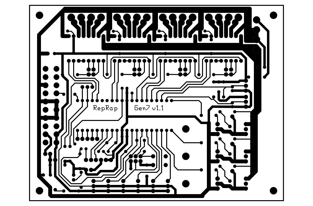
End (hopefully) of the story is, HEATER1 and HEATER2 pins are about to be re-wired. Here's how I think it should look:
P.S.: I got a notice FiveD could do without PWM, just this guy doesn't.
Edited 1 time(s). Last edit at 03/10/2011 06:43PM by Traumflug.
Sometimes it's astonishing how long it takes until quite essential flaws spring to someone's eye. More than three Gen7 1.0 boards were manufactured and they run at least 3 Mendels. Firmware is Teacup, as of a few weeks ago. Works smoothly, everything fine.
This week, some guy lurked around the corner, insisting to run FiveD on Gen7. So he got a board and tried. Doesn't work, because FiveD in turn insists on using PWM for the heaters. PWM only works on few selected ATmega pins.
End (hopefully) of the story is, HEATER1 and HEATER2 pins are about to be re-wired. Here's how I think it should look:

P.S.: I got a notice FiveD could do without PWM, just this guy doesn't.
Edited 1 time(s). Last edit at 03/10/2011 06:43PM by Traumflug.
| Generation 7 Electronics | Teacup Firmware | RepRap DIY |
|
Re: Generation 7 Electronics Development March 17, 2011 11:40AM |
Registered: 13 years ago Posts: 9 |
Im in the process of building my board but.......
I made the mistake of ordering the voltage regulated pololu's...... which dont have the proper clearance to install onto this board...
Ive been trying to make a replacement component for the existing pololu headers in the schematic, and try and orient them portrait vs landscape to fit (which at that point it wont be single-sided... which is fine for me)
im having trouble understanding GEDA, im used to KICAD..... would anybody have a good idea where i can find instructions to modify components? let alone one in an existing schematic.....
I cant return the pololus either because i was so exited when they arrived i couldnt help but solder the headers on...
: /
|
Re: Generation 7 Electronics Development March 18, 2011 08:04AM |
Registered: 13 years ago Posts: 7,616 |
I do footprint tweaking by opening a footprint in gEDA and a text editor simulnanuously. Then correct the items in the text editor while reviewing the results in gEDA (use Menu -> File -> Revert often). These two should get you started: [www.brorson.com] and [www.brorson.com]
Regarding symbol creation, these two are helpful: [geda.seul.org] and [geda.seul.org] Symbol creation works fine in the GUI.
For replacing a footprint, delete the old footprint, save the layout, close the layout editor, then click "update layout" in xgsch2pcb. You'll find the new footprint(s) in the upper left corner. Symbols are replaced by deleting and inserting a new one.
| Generation 7 Electronics | Teacup Firmware | RepRap DIY |
|
Re: Generation 7 Electronics Development March 28, 2011 07:30AM |
Registered: 13 years ago Posts: 7,616 |
Generation 7 Electronics version 1.1 is released: [reprap.org]
Besides a few bug and mess fixes, it features now it's own Arduino IDE plugin and has release files for our buddy Windows users: [github.com]
Besides a few bug and mess fixes, it features now it's own Arduino IDE plugin and has release files for our buddy Windows users: [github.com]
| Generation 7 Electronics | Teacup Firmware | RepRap DIY |
|
Re: Generation 7 Electronics Development April 15, 2011 08:10PM |
Registered: 13 years ago Posts: 9 |
|
Re: Generation 7 Electronics Development April 16, 2011 03:33AM |
Registered: 13 years ago Posts: 7,616 |
Well, firmware is firmware and is seperately from the hardware. Some people are running Teacup on Gen7 and at elast one is running FiveD. I've attached a config.h which isn't perfect yet, but should get you started.
| Generation 7 Electronics | Teacup Firmware | RepRap DIY |
|
Re: Generation 7 Electronics Development April 21, 2011 01:28AM |
Registered: 13 years ago Posts: 9 |
I took the Atmega 664p from my sanguino and flashed it with the gen 7 firmware (in my sangunio) and then placed it into the gen 7 board i have.... the icp and the serial will not respond to any of my commands.... lights are on but no ones home.... checked all voltages.... anyone know where i should start? i went back and checked for shorts.... for like 2 hours...... what should i do?
I even revert the bootloader back to stock and the gen7 board dosent respond to my commands...
Edited 1 time(s). Last edit at 04/21/2011 01:30AM by vis0r.
I even revert the bootloader back to stock and the gen7 board dosent respond to my commands...
Edited 1 time(s). Last edit at 04/21/2011 01:30AM by vis0r.
|
Re: Generation 7 Electronics Development April 21, 2011 04:07AM |
Registered: 13 years ago Posts: 7,616 |
Hmm. There is no Gen7-specific firmware. The bootloader is only specific in that it also has versions compiled for 20 MHz.
What stops you from flashing the firmware while the ATmega is in plugged into the Gen7 board?
For general testing, I usually use the Basics/DigitalSerialRead program from the set of example projects in the Arduino IDE. That should send you back zeros at 9600 baud.
What stops you from flashing the firmware while the ATmega is in plugged into the Gen7 board?
For general testing, I usually use the Basics/DigitalSerialRead program from the set of example projects in the Arduino IDE. That should send you back zeros at 9600 baud.
| Generation 7 Electronics | Teacup Firmware | RepRap DIY |
|
Re: Generation 7 Electronics Development April 26, 2011 12:29AM |
Registered: 12 years ago Posts: 40 |
|
Re: Generation 7 Electronics Development April 26, 2011 07:32AM |
Registered: 13 years ago Posts: 7,616 |
Release 1.2 will have new endstops, the main board unchanged. The design is on Github already, just lacking some cleanup.
| Generation 7 Electronics | Teacup Firmware | RepRap DIY |
|
Re: Generation 7 Electronics Development April 26, 2011 03:09PM |
Registered: 12 years ago Posts: 40 |
|
Re: Generation 7 Electronics Development April 27, 2011 05:24AM |
Registered: 13 years ago Posts: 7,616 |
|
Re: Generation 7 Electronics Development May 13, 2011 12:42PM |
Registered: 13 years ago Posts: 9 |
I finished my board last night, uploaded the boot-loader, and uploaded teacup with the config file provided.
When i connect to the com port with the Reprap host software and try to nudge an axis it freezes after saying that the line of gcode was Dequeued and sent...
i cant find anything regarding the topic so i figured id start here...
When i connect to the com port with the Reprap host software and try to nudge an axis it freezes after saying that the line of gcode was Dequeued and sent...
i cant find anything regarding the topic so i figured id start here...
|
Re: Generation 7 Electronics Development May 13, 2011 03:40PM |
Registered: 13 years ago Posts: 7,616 |
If you managed to upload the firmware, you had a connection to the ATmega and the board basically works.
You abviously don't get a connection to the firmware, though. Does the host try to connect at 115200 baud? If yes, you might want to fire up a serial terminal and issue a few commands by hand. After a reset, "start" ist sent and "M114" should send you back the robot position.
You abviously don't get a connection to the firmware, though. Does the host try to connect at 115200 baud? If yes, you might want to fire up a serial terminal and issue a few commands by hand. After a reset, "start" ist sent and "M114" should send you back the robot position.
| Generation 7 Electronics | Teacup Firmware | RepRap DIY |
|
Re: Generation 7 Electronics Development May 13, 2011 03:43PM |
Registered: 13 years ago Posts: 7,616 |
Before I forget it: Generation 7 Electronics version 1.2 is released: [reprap.org]
Now there are endstops for the TCST1103/2103 optical interrupter and the need for the end-of-life H21LOB is gone.
Now there are endstops for the TCST1103/2103 optical interrupter and the need for the end-of-life H21LOB is gone.
| Generation 7 Electronics | Teacup Firmware | RepRap DIY |
|
Re: Generation 7 Electronics Development May 17, 2011 01:52PM |
Registered: 13 years ago Posts: 75 |
|
Re: Generation 7 Electronics Development May 17, 2011 03:39PM |
Registered: 13 years ago Posts: 632 |
Some of the linked firmwares for Gen7 are I think from1.0 so pinouts are a little different. I had the most success just downloading the most recent teacup firmware and using the pinout guide on the Gen7 Page to adjust pins in the config.h.somegenericwordhere (I forget what the generic config.h file is called in the teacup directory  then save it as your config.h. You can use the published config.h for Gen7 as a guide, but I would use it as a reference rather than as a drop in solution. Just my 2 cents. It worked for me. Plus, you will want to become intimately familiar with your config.h file anyway, so you might as well jump in with both feet.
then save it as your config.h. You can use the published config.h for Gen7 as a guide, but I would use it as a reference rather than as a drop in solution. Just my 2 cents. It worked for me. Plus, you will want to become intimately familiar with your config.h file anyway, so you might as well jump in with both feet.
|
Re: Generation 7 Electronics Development May 18, 2011 09:05AM |
Registered: 13 years ago Posts: 75 |
Hi i have made this board:
i thinks its a middle way of gen 1.0 and 1.1
with the firmware basic of teacup-only to run motos- work good
but when i modified the config to read the thermistor and to power on th heater the motor wont work
another problem that i wasn't able to use the opto
i have made this config-attached-
can anyone help me??
|
Re: Generation 7 Electronics Development May 18, 2011 10:00AM |
Registered: 13 years ago Posts: 7,616 |
Lory, you've hit something not far after the 1.0 release, so pinouts of 1.0 apply.
Another one is, Teacup so far doesn't support STEPS_PER_MM bigger than 500, which is a reason why a motor won't turn. This limitation of Teacup is worked on right these days, so if you check out Teacup as of today, at least the X motor should work. The others are following as soon as X is tested a bit. If you don't want to wait that long, reduce to half stepping (no jumper) for now.
Also, as the pinout matches 1.0, Jacky2k's version of Teacup should work: [forums.reprap.org]
| Generation 7 Electronics | Teacup Firmware | RepRap DIY |
|
Re: Generation 7 Electronics Development June 04, 2011 03:39PM |
Hello reprappers,
I'm currently in a half of building my repstrap. Gen3 is too expensive for me and found this board. I like this design and as someone here asked for EAGLE version, here it is. It's a bit changed as I added wall wart power section. Board needs to be checked by someone more experienced in electronics than me. As I'm planning to use this design so can someone check it, correct and reupload EAGLE files?
Thanks,
Mark
|
Re: Generation 7 Electronics Development June 05, 2011 02:06PM |
Registered: 13 years ago Posts: 7,616 |
Looks good, Mark! I'd just make the tracks for the high current stuff (heaters, steppers) thicker. As much as possible :-)
| Generation 7 Electronics | Teacup Firmware | RepRap DIY |
|
Re: Generation 7 Electronics Development June 05, 2011 07:50PM |
Registered: 13 years ago Posts: 632 |
|
Re: Generation 7 Electronics Development June 06, 2011 04:24AM |
Registered: 13 years ago Posts: 28 |
|
Re: Generation 7 Electronics Development June 06, 2011 04:52AM |
Registered: 13 years ago Posts: 7,616 |
Quote
sorry if this is a stupid question,but: if you have a blank ATmega, and no programmer, can you use an ordinary arduino to upload to it? what wires would you use?
Not a stupid question at all. Arduinos can indeed be programmed to act as a programmer: [arduino.cc] [arduino.cc]
| Generation 7 Electronics | Teacup Firmware | RepRap DIY |
|
Re: Generation 7 Electronics Development June 06, 2011 06:55AM |
Registered: 13 years ago Posts: 28 |


Sorry, only registered users may post in this forum.