Generation 7 Electronics Development
Posted by Traumflug
|
Re: Generation 7 Electronics Development June 06, 2011 11:05AM |
Registered: 12 years ago Posts: 17 |
Hi!
I'm glad it looks fine. I'm uploading as an attachment latest corrected version. Added power rails (+12V, 5V and GND) polygons, moved few lines and mounting holes. Also in attachment are EAGLE gerb274x.cam job generated bottom (copper layer) and top silkscreen. *.bom and *.qty files are list of components and number of used components, may be useful I think.
Regards,
Mark
|
Re: Generation 7 Electronics Development June 06, 2011 05:31PM |
Registered: 13 years ago Posts: 7,616 |
Quote
would this work for the small atmega on an arduino,connected to the 644 one on the gen7 board?
You have to try that. Regarding programming, a Gen7 board acts just like an Anruino or Sanguino.
Quote
another question i had was whether a ttl to usb adapter would work,rather than a full cable,as the pins are slightly different?
You see:

I have a board-like adapter as well. The pinout must be correct, of course. Compare it this: [reprap.org]
| Generation 7 Electronics | Teacup Firmware | RepRap DIY |
|
Re: Generation 7 Electronics Development June 06, 2011 05:48PM |
Registered: 13 years ago Posts: 7,616 |
Folks, what do you think of that?
A whole bunch of reviewed connectors, and a new one to get enough current to the heated bed. Should easily allow to run a heated bed right off the board. Best of all, advanced users can put different voltages to heaters and motors. For example, 24 volts to the Pololus, 12 volts to the heaters. Or 3.3 volts to the spark erosion pin instead of the heaters.
Some people suggested to use the ATX12V connector instead of another disk power connector. That ATX12V one has thinner wires, so the gain isn't as much as one could think. Also, it isn't present on pre-ATX12V supplies.
| Generation 7 Electronics | Teacup Firmware | RepRap DIY |
|
Re: Generation 7 Electronics Development June 07, 2011 02:06AM |
Registered: 15 years ago Posts: 478 |
Both versions are looking very good !
I think the Eagle version stands a better chance of Iorn on transfer as all the signal lines are a little thicker.
Great work is there any chance of a 1:1 scale PDF file for Iorn on Etching?
I usualy use Kikad as its open source and compared to Eagle when you print to a lazer printer it is printed to scale.
On Eagle its a right pain printing measuring and adjusting both of the scale factors ~ unless some one knows of another way?
Maybe this is a feature of the free version of Eagle and not in a final version.?
Bodge It [reprap.org]
=======================================
My rep strap: [repstrapbertha.blogspot.com]
Buy the bits from B&Q pipestrap [diyrepstrap.blogspot.com]
How to Build a Darwin without any Rep Rap Parts [repstrapdarwin.blogspot.com]
Web Site [www.takeaway3dtech.com]
|
Re: Generation 7 Electronics Development June 07, 2011 02:20AM |
Admin Registered: 16 years ago Posts: 13,884 |
... i'm using the free version of Eagle too and adjust scale-printing in the printer driver.
But mostly i'm exporting CNC-code for my mill ...
Viktor
--------
Aufruf zum Projekt "Müll-freie Meere" - [reprap.org] -- Deutsche Facebook-Gruppe - [www.facebook.com]
Call for the project "garbage-free seas" - [reprap.org]
But mostly i'm exporting CNC-code for my mill ...
Viktor
--------
Aufruf zum Projekt "Müll-freie Meere" - [reprap.org] -- Deutsche Facebook-Gruppe - [www.facebook.com]
Call for the project "garbage-free seas" - [reprap.org]
|
Re: Generation 7 Electronics Development June 07, 2011 05:06AM |
Registered: 15 years ago Posts: 478 |
I have the Print driver for my HP LaserJet 2100 PCL6 set to 1:1.
Printing with scale set to 1:1 works fine with PDF files, Direct prints from Kicad, Direct prints from Solid Edge 2D drafting ST3
Not working If using with Eagle even with Eagle scale set to 1:1 the final print is out by a diffrent factor depending on the board size used in a design.
So you need to measure the print in X and Y and re-scale maybe twice to get an acurate print.
Maybe its becauise the Gen7 board is 5.2" x 4.25 " thus bigger than 4" x 3.2" the free Eagle SW alows ?
Or
an Eagle print is based on the board displayed on the screen not on an image created from the data that is used to create the final Gerber files.
Bodge It [reprap.org]
=======================================
My rep strap: [repstrapbertha.blogspot.com]
Buy the bits from B&Q pipestrap [diyrepstrap.blogspot.com]
How to Build a Darwin without any Rep Rap Parts [repstrapdarwin.blogspot.com]
Web Site [www.takeaway3dtech.com]
|
Re: Generation 7 Electronics Development June 07, 2011 06:11AM |
Registered: 13 years ago Posts: 7,616 |
Quote
I think the Eagle version stands a better chance of Iorn on transfer as all the signal lines are a little thicker.
You mean thicker tracks help in some manufacturing processes? Currently, the minimum track width is 20 mil, which is plenty for traditional manufacturing processes. I'll see how much I can raise that without interfering with isolation milling (minimum isolation gap between tracks).
Quote
Great work is there any chance of a 1:1 scale PDF file for Iorn on Etching?
File -> Export layout ... -> PS
This gives you a PostScript file, scaled 1:1 (make sure the checkmark says so) and can be converted to PDF easily. gEDA/pcb even has a printer calibration function, also in the File menu.
PDF files are also included in the "release files" section in the Github repo. Updated on every release ...
| Generation 7 Electronics | Teacup Firmware | RepRap DIY |
|
Re: Generation 7 Electronics Development June 07, 2011 02:41PM |
Registered: 13 years ago Posts: 632 |
I'm not a real pro at toner transfer etching, so I generally oversize the traces and undersize the holes in the pads. This makes it more likely to get a good board. Toner transfer can be a bit of a pain. It is kitchen science in every way. Plus, since you are often drilling pads by hand it helps to oversize the pads too. Wider traces and smaller holes help the most. The wider traces help avoid open traces when etching is finished, and undersized holes helps avoid pads that etch too thin and are then liable to pop off the board when soldering. Also a smaller hole helps center the drill bit better.
|
Re: Generation 7 Electronics Development June 07, 2011 02:55PM |
Registered: 13 years ago Posts: 632 |
|
Re: Generation 7 Electronics Development June 07, 2011 04:50PM |
Registered: 15 years ago Posts: 478 |
In the version of Eagle I have the Export function has not got File -> Export layout ... -> PS
It onlly has Image which is a PNG file.
If I delete the polygons
Then set background colour to white it is usualy black
File -> Export Image
Set the resolution to 600 dpi
Tick the monchrome radio button
I then get a valid PNG File
Import the PNG into Inkscape.
Scale the png to the board size
Then flip it to get a miror image
Draw a border around the image
Cut and paste to an A4 page twice as transfers do not always work first time.
Its looking good to print onto transfer paper.
Having just made one of the best toner transfer boards so far only to realize, I did not need to flip the image is a tiny bit annoying!!
The PDF is now correct.
OOOPs [picasaweb.google.com]
Edited 3 time(s). Last edit at 06/07/2011 10:37PM by BodgeIt.
Bodge It [reprap.org]
=======================================
My rep strap: [repstrapbertha.blogspot.com]
Buy the bits from B&Q pipestrap [diyrepstrap.blogspot.com]
How to Build a Darwin without any Rep Rap Parts [repstrapdarwin.blogspot.com]
Web Site [www.takeaway3dtech.com]
It onlly has Image which is a PNG file.
If I delete the polygons
Then set background colour to white it is usualy black
File -> Export Image
Set the resolution to 600 dpi
Tick the monchrome radio button
I then get a valid PNG File
Import the PNG into Inkscape.
Scale the png to the board size
Draw a border around the image
Cut and paste to an A4 page twice as transfers do not always work first time.
Its looking good to print onto transfer paper.
Having just made one of the best toner transfer boards so far only to realize, I did not need to flip the image is a tiny bit annoying!!
The PDF is now correct.
OOOPs [picasaweb.google.com]
Edited 3 time(s). Last edit at 06/07/2011 10:37PM by BodgeIt.
Bodge It [reprap.org]
=======================================
My rep strap: [repstrapbertha.blogspot.com]
Buy the bits from B&Q pipestrap [diyrepstrap.blogspot.com]
How to Build a Darwin without any Rep Rap Parts [repstrapdarwin.blogspot.com]
Web Site [www.takeaway3dtech.com]
|
Re: Generation 7 Electronics Development June 08, 2011 02:35AM |
Registered: 13 years ago Posts: 7,616 |
Quote
I have my Gen7 V1.2 board running on a Prusa.
Nice!
Bonus points, if you could elaborate a bit on how to get the firmware up. Especially the part with the extruder, as some people are stuck in this area and I don't have an extruder myself, yet.
Quote
In the version of Eagle I have the Export function has not got File -> Export layout ... -> PS
I should have mentioned it, this was meant for gEDA. The really unfortunate thing is, gEDA is buildable on/for Windows, but gEDA people don't publish such a build for licensing reasons.
Glad you got it worked out, though.
| Generation 7 Electronics | Teacup Firmware | RepRap DIY |
|
Re: Generation 7 Electronics Development June 08, 2011 12:23PM |
Registered: 12 years ago Posts: 17 |
I've attached .ps image of EAGLE Gen7 version. In EAGLE you can print to file (Postscript). This way exported PCB looks good and can be printed. I used GIMP to import ps file at max resolution with maximum smoothing which gives even better results than directly from EAGLE. I'll make one soon and test it. If anyone wants I can share photos from thermotransfer and after etching.
Nice work with getting it working.
Regards,
Mark
Nice work with getting it working.
Regards,
Mark
|
Re: Generation 7 Electronics Development June 08, 2011 04:38PM |
Registered: 13 years ago Posts: 7,616 |
Toner transfer etching guys, you might be interested in this, just fresh from my garage: [reprap.org]
| Generation 7 Electronics | Teacup Firmware | RepRap DIY |
|
Re: Generation 7 Electronics Development June 08, 2011 05:39PM |
Registered: 13 years ago Posts: 632 |
 I'll have to use up my two Gen7 1.2 boards and get to etchin the new version sometime soon.
|
Re: Generation 7 Electronics Development June 09, 2011 05:23AM |
Registered: 13 years ago Posts: 1,352 |
I totally love this new change. That is to give different voltage to motors and heaters and separate feed for "logic" supply regulators - would love that in other stepper drivers etc.
Some thoughts. I propose:
1) positioning the big atx connector to the other side near the fets;
2) making D1 and D2 vertical and leave 3 way connectors, basically with V+, GND_in and GND_switched instead;
Also:
3) GND in at the at the fet connectors and none at the V+input connectors;
4) consider changing the atx connectors to simpler connectors (same style as the heater outputs): V+motors, V+heaters, V+logic to the v_regulator(s), and PSU_ON;
1) Length
Trace width matter in a manner that is better to be as big as possible - the bigger it is, the lower resistance it has, then the lower the temperature rise and respective voltage drop. Something like [circuitcalculator.com] For 10 amps it shoulnd be underestimated (e.g. high currents pcbs use 70um copper layer height). The other impact factor at hand is obviously the length of it. For example the GND trace has some length (ignoring that milling wouldnt mind for it as will be wider than "drawn"). To minimize this path length and also maybe multi-gnd paths turbionary effects, then the fets should be positioned near the "current in" connectors (or viceversa). E.g. like in EC 2.2. I didnt figured how problematic HB current is untill i noticed its 10A cables (normal pc cables for mains) are heated untill are spaghetti quality.
2) two or three pins connectors for fets
The part where it got 2 pin connectors instead of 3. The old 3 pins connectors could allow for a somewhat different config, that is to use the V+ directly from psu to the Heated Bed, and only the gnd like to touch the pcb, and not from one side to the other, but only from 2nd pin to the 3rd pin of the connector, the fet being arranged in between. Small length traces could be "fattened" with solder to decrease resistance, so in that manner much bigger currents can be worked without interfering with anything else etc. These ought to be like at least 14A rated so package is probably 5.08" pin spacing.
3) point of GND going in
The paralleled wiring of two or more grounds considerations:
- if the resistance difference is big enough (logic path intentionally made somewhat slimmer), then the ideea is that the 99% of the current will go with the lower resistance path
- turbionary currents inside ic units: providing that the gnd of the heater connector is much better compared with the one coming from the molex or other smaller connectors, the latter can be dropped at all and leave only the gnd from the fets to be active. If all fets are together there is no turbionary currents for ic as gnd all paths unite after them leaving a possible start config for the rest of board.
4) normal atx connectors take a heck of board space; as advange it can be said that they are easy, true, but probably thats all they are. Two ways: one can open 8 screws and solder some proper wiring to the psu, or second, leave the atx alone and still use these connectors but do so outside, near the board with short wiring to the board. Loosing some elegance but gaining some space and maybe clarity.
To use diff voltages, a good point is to have the path to voltage regulators separated, for example these could take only up to 30V (78Lxx) or 35V (78xx) or 37V (others) and even at these max the dissipation is probably huge depending on package, so actual feed should be less. In opposition, one could choose to run the motors at 40V, and separate lower voltage can make it happen, otherwise would need heatink or another v_reg in position of a "preregulator" and sharing disipation to both.
Btw, thanks for the G7 electronic which is pretty nice one - good job. Cheers.
|
Re: Generation 7 Electronics Development June 09, 2011 06:27AM |
Registered: 13 years ago Posts: 1,352 |
In the trace width calculator above, for normal 35um pcb, 10 amps at 10 cm length and approx 3.69mm width gives approx 0.0155 ohms further estimated at approx 1.55 watts disipation. It is a pretty good value for a low side shunt resistor at this current. That is input its trace ends to a adc in differential mode, or to an op amp to scale its single output to max current = max adc (maybe a self calibration routine). This way it can read and display the current usage and consumptions - isnt that nice as a feature?
|
Re: Generation 7 Electronics Development June 09, 2011 08:20AM |
Registered: 13 years ago Posts: 7,616 |
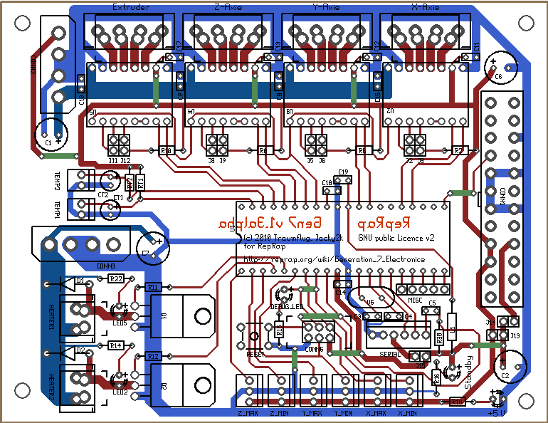
As requested on IRC, here's a PDF of the current status
Gen7Board.pdf
Gen7Board.pdf
| Generation 7 Electronics | Teacup Firmware | RepRap DIY |
|
Re: Generation 7 Electronics Development June 09, 2011 04:20PM |
Registered: 15 years ago Posts: 478 |
neonek911
Thank you for that Gen7_ICSP.ps file
Unfotunatly using adobe to read or translate it to PDF the PCB image is printed 10mm too high for A4 paper.
So I nstalled Gimp 2 for Windows unfotunatly the Windows version of Gimp2 has not got the file Ghostscript.
When you say maximum resolution do you mean all the 9s in the top feild of pic2 ?
The part I can print is very good.. just need the other 10mm to make a board..
Bodge It [reprap.org]
=======================================
My rep strap: [repstrapbertha.blogspot.com]
Buy the bits from B&Q pipestrap [diyrepstrap.blogspot.com]
How to Build a Darwin without any Rep Rap Parts [repstrapdarwin.blogspot.com]
Web Site [www.takeaway3dtech.com]
Thank you for that Gen7_ICSP.ps file
Unfotunatly using adobe to read or translate it to PDF the PCB image is printed 10mm too high for A4 paper.
So I nstalled Gimp 2 for Windows unfotunatly the Windows version of Gimp2 has not got the file Ghostscript.

When you say maximum resolution do you mean all the 9s in the top feild of pic2 ?

The part I can print is very good.. just need the other 10mm to make a board..
Bodge It [reprap.org]
=======================================
My rep strap: [repstrapbertha.blogspot.com]
Buy the bits from B&Q pipestrap [diyrepstrap.blogspot.com]
How to Build a Darwin without any Rep Rap Parts [repstrapdarwin.blogspot.com]
Web Site [www.takeaway3dtech.com]
|
Re: Generation 7 Electronics Development June 10, 2011 02:09AM |
Registered: 13 years ago Posts: 7,616 |
Regarding Adobe Reader: you very likely can adjust the scaling of the print in the print dialog. Just get rid of this "fit to papersize" function, or whatever tries to adjust the scaling automatically. If that fails, try with a custom paper size, 10 mm larger than your actual paper.
Regarding Gimp: GhostScript is an extra install, another application.
Regarding Gimp: GhostScript is an extra install, another application.
| Generation 7 Electronics | Teacup Firmware | RepRap DIY |
|
Re: Generation 7 Electronics Development June 10, 2011 10:49AM |
Registered: 12 years ago Posts: 17 |
Hi!
By maximum resolution I meant setting resolution to something about 600 or above and Graphics antialiasing to Strong. I had problems with converting .ps to .pdf. Anyway in attachment you can find centered board image in .ps file and converted .pdf. PDF looks bad, really. Polygons are striped not solid, but maybe you can somehow use it. I don't have access to Windows so I can't check if it works or not.
Regards,
Mark
|
Re: Generation 7 Electronics Development June 10, 2011 10:57PM |
Registered: 15 years ago Posts: 478 |
neonek911
Thank you yes that solves the problem perfectly..
The stripes are a display problem Adobe seems to have when viewing in certain zoom resolutions.
Zoom in or out the stipes vanish will etch your new version tomorow. The CPUs & Fets arrived yesterday.
Traumflug
I installed GhostScript I failed to get it recognized in Gimp or was adjusting the wrong enviroment variable ?
Its been a bad week for SW trying to set a diffrent origin point on a drawing sheet in Solid Edge 2D Drawing ST3 has beaten me. I found instructions for Auto Cad but not for the Solid Edge Free version. Maybe its an option in the set up. I missed setting a custom sheet size also evaded me as save as default fails to save the new custom sheet size in the application default.
Bodge It [reprap.org]
=======================================
My rep strap: [repstrapbertha.blogspot.com]
Buy the bits from B&Q pipestrap [diyrepstrap.blogspot.com]
How to Build a Darwin without any Rep Rap Parts [repstrapdarwin.blogspot.com]
Web Site [www.takeaway3dtech.com]
|
Re: Generation 7 Electronics Development June 11, 2011 05:09AM |
Registered: 12 years ago Posts: 17 |
Hi!
Nice to hear it helped. Not only Adobe has these problems, Ubuntu document reader also shows these stripes but it doesn't depend on zoom.
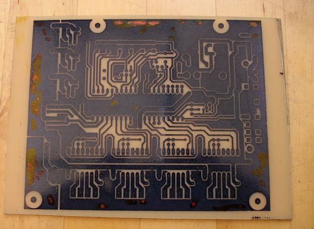
Regarding etching and assembly, I can provide image with reduced holes size for easier drilling. And I have swapped X_MIN and X_MAX endstops for easier routing. So X_MAX endstop MISO line is furthest right endstop. ICSP header is standard. There is also unconnected (Unrouted layer) +12V trace, you have to connect it the via under X Pololu driver, but only if using wall-wart power supply I think.
There is a lot of clearance and overlapping errors but all traces are OK, We'll see if it works.
Thanks for your interest and involvement,
Mark
Nice to hear it helped. Not only Adobe has these problems, Ubuntu document reader also shows these stripes but it doesn't depend on zoom.
Regarding etching and assembly, I can provide image with reduced holes size for easier drilling. And I have swapped X_MIN and X_MAX endstops for easier routing. So X_MAX endstop MISO line is furthest right endstop. ICSP header is standard. There is also unconnected (Unrouted layer) +12V trace, you have to connect it the via under X Pololu driver, but only if using wall-wart power supply I think.
There is a lot of clearance and overlapping errors but all traces are OK, We'll see if it works.
Thanks for your interest and involvement,
Mark
|
Re: Generation 7 Electronics Development June 11, 2011 06:28AM |
Registered: 15 years ago Posts: 478 |
Thank you Mark ....
What is an overlapping error.. is it like you had to do in the days of blue red tape or even black tape where you had to overlap all the track tape joins to stop light going thru.. ?
Would you mind making another PDF with the alterd lay out? I need to use the wallwart variet as I only run on 24-30v Single supplies don't use PC PSUs even though I have loads.. of them..
Most are over 10 years old or more// Closed my computer shop in 1998 after 10 years still have stacks of computer junk despite dumping >70 old computers at the time, Amigas, Ataris & PCs.
I've even re-used bits of PC case to repair cars its nice thick steel easy for an amatur welder to use without blowing holes straight thru it.
Bodge It [reprap.org]
=======================================
My rep strap: [repstrapbertha.blogspot.com]
Buy the bits from B&Q pipestrap [diyrepstrap.blogspot.com]
How to Build a Darwin without any Rep Rap Parts [repstrapdarwin.blogspot.com]
Web Site [www.takeaway3dtech.com]
|
Re: Generation 7 Electronics Development June 11, 2011 07:13AM |
Registered: 12 years ago Posts: 17 |
Hi!
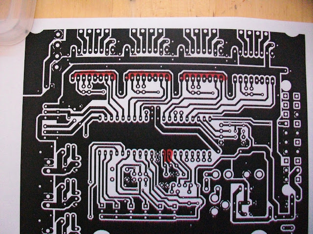
Overlapping errors are caused by polygons drawn one on another but they calculate well as you can see in ps/pdf images, no shorts. PDF posted before is OK for wall-wart power supply, you just need to solder additional jumper wire for motor power rail, the longest red one in attached image (PCB+jumpers.png). After school year end (22.06) I'll try to etch a few boards and post full assembly instructions. Sorry, but for now you have to refer to schematic/board layout files for assembly. Also there are board images with reduced to 0.5mm holes (ps and pdf format).
Wow, nice collection and creative mind BTW.
Regards,
Mark
|
Re: Generation 7 Electronics Development June 13, 2011 07:31AM |
Registered: 15 years ago Posts: 478 |
Using Maplin PCB transfer film as I have run out of the right sort of pound shop label backing this laser transfer method is about 4 x more expensive @ £16.99 for a pack of 5 sheets. Most effect way to use clean board with nail varish remover do not pre-heat as per offical instructions just Iorn on for 5 min let it cool for two min then run under cold water peel inspect touch up with water proof maker I use a red CD marker so i can see it. Then etch this took 15 min in old feric at 45C ish.
Original board
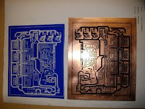
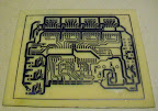
New board

Some of the tracks are a little to close for DIY etching but a dremel with a 0.2mm engraving tip will solve them.
Etching number two board drilling and building next then designing a box with fan.. flashing testing and connecting to two Huxley seedling prototypes. as soon as the 0.9 degree steppers arrive hopefully sooner than their predicted ETA.
Again thank you neonek911 for posting the Gen7_ICSP_drillaid.pdf file and of course to Traumflug for a neat DIY able at home PCB design .
Edited 1 time(s). Last edit at 06/13/2011 07:38AM by BodgeIt.
Bodge It [reprap.org]
=======================================
My rep strap: [repstrapbertha.blogspot.com]
Buy the bits from B&Q pipestrap [diyrepstrap.blogspot.com]
How to Build a Darwin without any Rep Rap Parts [repstrapdarwin.blogspot.com]
Web Site [www.takeaway3dtech.com]
Original board
New board
Some of the tracks are a little to close for DIY etching but a dremel with a 0.2mm engraving tip will solve them.
Etching number two board drilling and building next then designing a box with fan.. flashing testing and connecting to two Huxley seedling prototypes. as soon as the 0.9 degree steppers arrive hopefully sooner than their predicted ETA.
Again thank you neonek911 for posting the Gen7_ICSP_drillaid.pdf file and of course to Traumflug for a neat DIY able at home PCB design .
Edited 1 time(s). Last edit at 06/13/2011 07:38AM by BodgeIt.
Bodge It [reprap.org]
=======================================
My rep strap: [repstrapbertha.blogspot.com]
Buy the bits from B&Q pipestrap [diyrepstrap.blogspot.com]
How to Build a Darwin without any Rep Rap Parts [repstrapdarwin.blogspot.com]
Web Site [www.takeaway3dtech.com]
|
Re: Generation 7 Electronics Development June 13, 2011 09:21AM |
Registered: 12 years ago Posts: 17 |
Hi!
Boards are looking very good. Well done. Can you provide more info (mark your photo) about problematic places, so I can correct them? Nice to hear you'll use them. For my repstrap I've got almost all parts excluding thermistor which I can't find here in Poland ;(
It was pleasure re-making this design, thanks Traumflug.
Regards,
Mark
|
Re: Generation 7 Electronics Development June 13, 2011 10:06AM |
Registered: 15 years ago Posts: 478 |
Mark will do I will mark them up on a pdf
The strangest of strange things is that the parts that needed touching up on both transfers were almost exactly the same parts.. will take a pic.. now both were printed on one sheet at the same time included the two up PDF
Its very strange I can not think of a reasonable explanation as to why transfer has not happened in the same places the bare PCB used was one piece cut in half they were ironed on a dead flat granite chopping block so it was not to do with flatness of the boards both insulated by two different free newspapers they were also oriented different ways as Ironed them on.. yet retain the same transfer flaws
Bodge It [reprap.org]
=======================================
My rep strap: [repstrapbertha.blogspot.com]
Buy the bits from B&Q pipestrap [diyrepstrap.blogspot.com]
How to Build a Darwin without any Rep Rap Parts [repstrapdarwin.blogspot.com]
Web Site [www.takeaway3dtech.com]
|
Re: Generation 7 Electronics Development June 14, 2011 03:54AM |
Registered: 13 years ago Posts: 7,616 |
|
Re: Generation 7 Electronics Development June 14, 2011 03:04PM |
Registered: 15 years ago Posts: 478 |
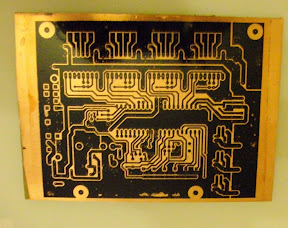
Percived problem areas for home etching however on taking close ups with a camera its very marginal so it may not be too bad.
Maybe just a tiny smidgen of extra clearance.
Just drilled out two boards to 0.6mm holes will now try and figure out the ones that need to be bigger next.
Have just orderd connectrors
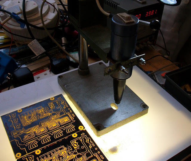
Here is a pic of the drill used I bought it when I was 16 > 39 years ago and its still going,
Close up of boards showing tight areas..

The top right connection of the first three Pololu I have gently milled the edge of the pad using the 0.6mm drill if the track was at right angle instead of the 45 deg angle there would be no problem. The thrugh connection between the xtal pins is a little too tight slightly thiner pads or thru track maybe?

This is the other board.
Bodge It [reprap.org]
=======================================
My rep strap: [repstrapbertha.blogspot.com]
Buy the bits from B&Q pipestrap [diyrepstrap.blogspot.com]
How to Build a Darwin without any Rep Rap Parts [repstrapdarwin.blogspot.com]
Web Site [www.takeaway3dtech.com]
Maybe just a tiny smidgen of extra clearance.
Just drilled out two boards to 0.6mm holes will now try and figure out the ones that need to be bigger next.
Have just orderd connectrors
Here is a pic of the drill used I bought it when I was 16 > 39 years ago and its still going,
Close up of boards showing tight areas..
The top right connection of the first three Pololu I have gently milled the edge of the pad using the 0.6mm drill if the track was at right angle instead of the 45 deg angle there would be no problem. The thrugh connection between the xtal pins is a little too tight slightly thiner pads or thru track maybe?
This is the other board.
Bodge It [reprap.org]
=======================================
My rep strap: [repstrapbertha.blogspot.com]
Buy the bits from B&Q pipestrap [diyrepstrap.blogspot.com]
How to Build a Darwin without any Rep Rap Parts [repstrapdarwin.blogspot.com]
Web Site [www.takeaway3dtech.com]
|
Re: Generation 7 Electronics Development June 16, 2011 11:39AM |
Registered: 12 years ago Posts: 17 |
Hi!
Again, well done BodgeIt. Thanks for pointing problematic places. Now everything should be OK for home etching. Changed layout of pads on Pololu signal side, narrowed marked line between pads, also added jumper for those who don't want trace between pads. There's also one addition, OptoEndstop EAGLE re-design. Pinout and photo interrupter is the same as Traumflug but layout is different. In .zip/.tar.gz archives you can find source EAGLE files, .ps and .pdf board images and in OptoEndstop directory there are .ps/.pdf files for etching more board at once. Tomorrow, I think, I'll etch endstops and I may add WIP design of mechanical endstop I'm working on.
Externally hosted archives, forum file size restrictions:
Gen7 design .zip archive
Gen7 design .tar.gz archive
And something like a wish or polite request, can someone make a list of links to parts for easier ordering (help for me) in Mouser / Farnell ? I'd be very grateful for someone who'll make such a list (especially connectors).
Regards,
Mark


Sorry, only registered users may post in this forum.