Generation 7 Electronics Development
Posted by Traumflug
|
Re: Generation 7 Electronics Development June 17, 2011 05:21AM |
Registered: 15 years ago Posts: 478 |
I learnt how to design a Laser able Gen 7 box yesterday in my new Fablab at Home office (aka Hallway) these are as yet untested as I have not built the boards yet.. slip up with connectors I assumed 5.08 pitch pins they are slightly different so may just use vero pins to chocolate blocks if i can find the vero pins.

Any way here's is a preview of the Gen 7 box.. Midge is more Geeky than me as she wants a see thru one that means a re draw as 4mm Acrylic is expensive so I will do it in 2.5mm Acrylic.
Once the hole positions are tested will pop the design up on the WIKI ..
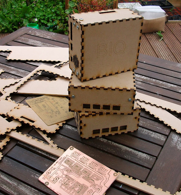
Why so many well I was going to glue it together then Midge said get two on a sheet then I thought might as well add fix it blocks so its easy to take apart after years of using fix it blocks. I got the hole positions wrong as I didnt use my saved template which was blasé.. so I now have two good boxes.. and some fire wood.
Edited 1 time(s). Last edit at 06/17/2011 05:37AM by BodgeIt.
Bodge It [reprap.org]
=======================================
My rep strap: [repstrapbertha.blogspot.com]
Buy the bits from B&Q pipestrap [diyrepstrap.blogspot.com]
How to Build a Darwin without any Rep Rap Parts [repstrapdarwin.blogspot.com]
Web Site [www.takeaway3dtech.com]
Any way here's is a preview of the Gen 7 box.. Midge is more Geeky than me as she wants a see thru one that means a re draw as 4mm Acrylic is expensive so I will do it in 2.5mm Acrylic.
Once the hole positions are tested will pop the design up on the WIKI ..
Why so many well I was going to glue it together then Midge said get two on a sheet then I thought might as well add fix it blocks so its easy to take apart after years of using fix it blocks. I got the hole positions wrong as I didnt use my saved template which was blasé.. so I now have two good boxes.. and some fire wood.
Edited 1 time(s). Last edit at 06/17/2011 05:37AM by BodgeIt.
Bodge It [reprap.org]
=======================================
My rep strap: [repstrapbertha.blogspot.com]
Buy the bits from B&Q pipestrap [diyrepstrap.blogspot.com]
How to Build a Darwin without any Rep Rap Parts [repstrapdarwin.blogspot.com]
Web Site [www.takeaway3dtech.com]
|
Re: Generation 7 Electronics Development June 17, 2011 12:43PM |
Registered: 13 years ago Posts: 28 |
another stupid question,or an amateurish one anyway,how do you do the bootloader programming sequence on windows?
.....
or,for that matter,at all? i looked for tutorials on it,any examples of what any of you did for this step?
thanks
Edited 1 time(s). Last edit at 06/17/2011 01:14PM by kenneth kneebone.
.....
or,for that matter,at all? i looked for tutorials on it,any examples of what any of you did for this step?
thanks
Edited 1 time(s). Last edit at 06/17/2011 01:14PM by kenneth kneebone.
|
Re: Generation 7 Electronics Development June 17, 2011 02:00PM |
Registered: 15 years ago Posts: 478 |
I use AVR studio 4... in Windows I have not flashed this board yet but here is how I did it on other boards.
I always go back to this post to remind myself. I use the blog mainly as a reminder of how I did some thing.
Like the pins on Sanguino Ive used etc..
Hope it helps you..
[repstrapbertha.blogspot.com]
Bodge It [reprap.org]
=======================================
My rep strap: [repstrapbertha.blogspot.com]
Buy the bits from B&Q pipestrap [diyrepstrap.blogspot.com]
How to Build a Darwin without any Rep Rap Parts [repstrapdarwin.blogspot.com]
Web Site [www.takeaway3dtech.com]
|
Re: Generation 7 Electronics Development June 20, 2011 05:45PM |
Registered: 12 years ago Posts: 43 |
Hi all,
I am hoping someone here can help me get my Gen 7 electronics programmed...
I have had a number of problems, the first being that I could not get the bootloader programmed successfully, although I think I have overcome this as everything verifies OK. Is there some way to confirm that it has worked properly? e.g. a command I can send over the serial link that will invoke some response? (I followed instructions on the Gen7 wiki post (http://reprap.org/wiki/Gen7_Board_1.2) using a windows machine with avrdude.)
My major issue is getting the firmware compiling. I am on a mac using the Arduino IDE. I have got the Gen7 support files in place and have selected Gen7 with ATmega644p 20MHz as my board. I have also selected my serial port. I followed the instruction at [reprap.org] for Teacup firmware but the compiler errors out with:
I have a general understanding of coding but have never used AVRs before. I assume that MUX5 is either a register that is not being recognised or a variable that has not yet been defined, but the code is way too indepth for me to understand any more than that.
I also tried the FiveD firmware. It compiled after I changed it to 644P. However when I attempt to program via the bootloader it throws up errors:
This suggests to me that the bootloader is not working. Does anybody have any thoughts?
Thanks
Andy
I am hoping someone here can help me get my Gen 7 electronics programmed...
I have had a number of problems, the first being that I could not get the bootloader programmed successfully, although I think I have overcome this as everything verifies OK. Is there some way to confirm that it has worked properly? e.g. a command I can send over the serial link that will invoke some response? (I followed instructions on the Gen7 wiki post (http://reprap.org/wiki/Gen7_Board_1.2) using a windows machine with avrdude.)
My major issue is getting the firmware compiling. I am on a mac using the Arduino IDE. I have got the Gen7 support files in place and have selected Gen7 with ATmega644p 20MHz as my board. I have also selected my serial port. I followed the instruction at [reprap.org] for Teacup firmware but the compiler errors out with:
analog.c: In function '__vector_24':
analog.c:84: error: 'MUX5' undeclared (first use in this function)
analog.c:84: error: (Each undeclared identifier is reported only once
analog.c:84: error: for each function it appears in.)
I have a general understanding of coding but have never used AVRs before. I assume that MUX5 is either a register that is not being recognised or a variable that has not yet been defined, but the code is way too indepth for me to understand any more than that.
I also tried the FiveD firmware. It compiled after I changed it to 644P. However when I attempt to program via the bootloader it throws up errors:
Binary sketch size: 24456 bytes (of a 63488 byte maximum)
avrdude: stk500_2_ReceiveMessage(): timeout
avrdude: stk500_2_ReceiveMessage(): timeout
This suggests to me that the bootloader is not working. Does anybody have any thoughts?
Thanks
Andy
|
Re: Generation 7 Electronics Development June 21, 2011 02:37AM |
Registered: 13 years ago Posts: 7,616 |
Quote
Is there some way to confirm that it has worked properly?
Upload one of Arduino IDE's example sketches. If it says "upload successful", the bootloader works fine.
For the other error: can't find the word "MUX5" anywhere in the Teacup sources. What version are you using?
| Generation 7 Electronics | Teacup Firmware | RepRap DIY |
|
Re: Generation 7 Electronics Development June 21, 2011 03:15AM |
Registered: 12 years ago Posts: 43 |
Hi Traumflug, thanks for the quick reply.
I am not at my dev computer right now so I cannot give you an exact number but I used the latest source from the github repository by clicking the "Downloads" button and getting the only file available. Looking at the files in the repository MUX5 appears in analog.c on lines 86 and 88. I had a quick look at the 644P datasheet and it looks like MUX4:0 is a register associated with the ADC function but no mention of MUX5 - if I was not the only one who seems to have problems I would say its the wrong register - but other people do not seem to have any issues, hence I think there is something wrong with my setup.
As far as the bootloader goes I was hoping for a means to test that it is loaded that does not rely on me compiling anything with the arduino software since I am not sure whether the software is working or not therefore a failed upload does not neccessarily mean the bootloader is not working, it might be the software failing, or my USB-Serial converter. Is there no way I can send characters on the serial port and get a response? at least that would narrow it down a bit.
Cheers
Andy
|
Re: Generation 7 Electronics Development June 21, 2011 07:43AM |
Registered: 13 years ago Posts: 7,616 |
Quote
Looking at the files in the repository MUX5 appears in analog.c on lines 86 and 88
You're right, it's me who was behind. This variable went into the repository just three days ago: [github.com]
Now, as this is a Teacup issue, here are a few ideas:
- use a slightly older version of Teacup, like [github.com]
- Write an "Issue" on Github: [github.com]
- Repeat in the big Teacup thread: [forums.reprap.org] , as others might be interested as well.
BTW.,
Quote
I also tried the FiveD firmware. It compiled after I changed it to 644P
Mustn't do that. The 644P has a different signature than the 644, so the bootloader on a 644 will reject attempts to upload a binary made for an 644P.
To test the bootloader, simply upload one of the examples coming with the Arduino IDE.
| Generation 7 Electronics | Teacup Firmware | RepRap DIY |
|
Re: Generation 7 Electronics Development June 21, 2011 07:47AM |
Registered: 13 years ago Posts: 7,616 |
P.S.: to compile FiveD, change occurences of __AVR_ATmega_644P__ to __AVR_ATmega_644__ . FiveD checks for CPU types instead of CPU features in some occurences.
| Generation 7 Electronics | Teacup Firmware | RepRap DIY |
|
Re: Generation 7 Electronics Development June 23, 2011 06:22AM |
Registered: 13 years ago Posts: 28 |
does anyone have a simple guide for the avr programming bit?
i tried this one avr tutorial but cant see how this and the instructions on the gen7 tutorial go together.
its all typed in the command line right? but not quite as is? [the dots are taken out yes? otherwise it doesnt recognise commands,also some others arent recognised,for example -b ]
sorry to bother you lot with a stupid question, i couldnt find a tutorial that i could make sense of related to this
thanks
|
Re: Generation 7 Electronics Development June 24, 2011 02:48AM |
Registered: 13 years ago Posts: 7,616 |
I don't have Windows, but let me take a guess.
Linux:
Linux:
Of course, you have to replace <your programmer> with the name of your programmer.
Does that work? If yes, please post the actually used command here, so everybody can learn. You can view recently used commands by hitting the arrow-up button.
Linux:
./avrdude -C ./avrdude.conf -c ?translates to Windows:
avrdude -C avrdude.conf -c ?
Linux:
./avrdude -C ./avrdude.conf -c <your programmer> -p atmega644 -P /dev/ttyACM0 \
    -B 5 -U lfuse:w:0xF7:m -U hfuse:w:0xDC:m -U efuse:w:0xFF:m
translates to Windows:avrdude -C avrdude.conf -c <your programmer> -p atmega644 -P COM1 \
-B 5 -U lfuse:w:0xF7:m -U hfuse:w:0xDC:m -U efuse:w:0xFF:m
Of course, you have to replace <your programmer> with the name of your programmer.
Does that work? If yes, please post the actually used command here, so everybody can learn. You can view recently used commands by hitting the arrow-up button.
| Generation 7 Electronics | Teacup Firmware | RepRap DIY |
|
Re: Generation 7 Electronics Development June 27, 2011 06:19AM |
Registered: 13 years ago Posts: 28 |
thankyou very much Traumflug, that DID work. 
as far as windows is concerned,now i only have to figure out how ive got the wiring wrong :/
it says:
C:\Documents and Settings\Home\Desktop\arduino-0022\hardware\tools>avrdude -C av
rdude.conf -c usbasp -p atmega644 -P COM1 \
found 2 busses
avrdude: error: programm enable: target doesn't answer. 1
avrdude: initialization failed, rc=-1
Double check connections and try again, or use -F to override
this check.
avrdude done. Thank you.
i'll see what i havent wired correctly,but your terminal commands seem to be fine
|
Re: Generation 7 Electronics Development June 28, 2011 02:20AM |
Registered: 13 years ago Posts: 7,616 |
Well, you'll have to find out which COM port your board is connected to. Or simply try COM1 ... COM8 until it works.
| Generation 7 Electronics | Teacup Firmware | RepRap DIY |
|
Re: Generation 7 Electronics Development July 01, 2011 07:28AM |
Registered: 13 years ago Posts: 28 |
|
Re: Generation 7 Electronics Development July 02, 2011 03:50AM |
Registered: 13 years ago Posts: 7,616 |
What's about COM2, COM3, COM4, COM5, COM6, COM7?
And please, can some Windows user help here? I have not much experience with proprietary software.
And please, can some Windows user help here? I have not much experience with proprietary software.
| Generation 7 Electronics | Teacup Firmware | RepRap DIY |
|
Re: Generation 7 Electronics Development July 04, 2011 03:08AM |
Admin Registered: 16 years ago Posts: 13,884 |
... check in hardware diagnosis/device manager which Com-ports are listed - one of them is your FTDI.
Or simply start the Arduino IDE and look in "Tools\Serial Port" which Com-ports are shown.
You have to wait some minutes after plugging in or reboot, until it's listed ...
Viktor
--------
Aufruf zum Projekt "Müll-freie Meere" - [reprap.org] -- Deutsche Facebook-Gruppe - [www.facebook.com]
Call for the project "garbage-free seas" - [reprap.org]
|
Re: Generation 7 Electronics Development July 07, 2011 04:16PM |
Registered: 13 years ago Posts: 1,352 |
After updating the latest FTDI drivers i get it on COM19 - so its not just 1-8 anymore.
Control panel - System - Hardware - Device manager - keep it open and when plugging the usb cable with the ft232 on the other end it will appear something under Ports (COM&LPT) - it will say USB Serial Port (COMxx). Right click on it - Properties, this tab and the next is Advanced - remember this spot you might make use of it later on.
Control panel - System - Hardware - Device manager - keep it open and when plugging the usb cable with the ft232 on the other end it will appear something under Ports (COM&LPT) - it will say USB Serial Port (COMxx). Right click on it - Properties, this tab and the next is Advanced - remember this spot you might make use of it later on.
|
Re: Generation 7 Electronics Development July 10, 2011 12:29PM |
Registered: 13 years ago Posts: 384 |
@BodgeIt: cool, can't wait to see the designs and build one for myself :p
reprapworld.com
PLA, ABS, PETG multiple colors (3 and 1.75 mm) €16,49 / kg
Megatronics 3.0 €79.99 / Minitronics €37,19
reprapworld.com
PLA, ABS, PETG multiple colors (3 and 1.75 mm) €16,49 / kg
Megatronics 3.0 €79.99 / Minitronics €37,19
|
Re: Generation 7 Electronics Development July 15, 2011 01:02AM |
Registered: 13 years ago Posts: 33 |
|
Re: Generation 7 Electronics Development July 15, 2011 01:53AM |
Admin Registered: 16 years ago Posts: 13,884 |
... yes, it works - i made adapters for my CNC-mill controller with cables and breakoutboard-sockets which fits in the sockets for the pololus ...
Viktor
--------
Aufruf zum Projekt "Müll-freie Meere" - [reprap.org] -- Deutsche Facebook-Gruppe - [www.facebook.com]
Call for the project "garbage-free seas" - [reprap.org]
Viktor
--------
Aufruf zum Projekt "Müll-freie Meere" - [reprap.org] -- Deutsche Facebook-Gruppe - [www.facebook.com]
Call for the project "garbage-free seas" - [reprap.org]
|
Re: Generation 7 Electronics Development July 15, 2011 05:29AM |
Registered: 13 years ago Posts: 33 |
VDX Wrote:
-------------------------------------------------------
> ... yes, it works - i made adapters for my
> CNC-mill controller with cables and
> breakoutboard-sockets which fits in the sockets
> for the pololus ...
Do you have a picture or even a PCB design for the adapters? Thanks.
-------------------------------------------------------
> ... yes, it works - i made adapters for my
> CNC-mill controller with cables and
> breakoutboard-sockets which fits in the sockets
> for the pololus ...
Do you have a picture or even a PCB design for the adapters? Thanks.
|
Re: Generation 7 Electronics Development July 15, 2011 05:50AM |
Admin Registered: 16 years ago Posts: 13,884 |
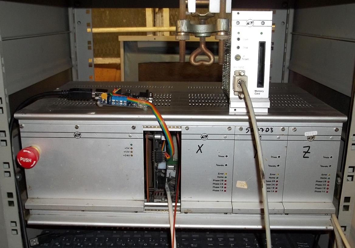
... atached are photos of the old interface board with Gen3 electronics and the board inserted in the CNC-controller.
Actually i'm interfacing an Arduino Mega with RAMPS and can post some photos of the 'pololu-adapters' later ...
Edited 1 time(s). Last edit at 07/15/2011 05:57AM by VDX.
Viktor
--------
Aufruf zum Projekt "Müll-freie Meere" - [reprap.org] -- Deutsche Facebook-Gruppe - [www.facebook.com]
Call for the project "garbage-free seas" - [reprap.org]
|
Re: Generation 7 Electronics Development July 15, 2011 02:43PM |
Admin Registered: 16 years ago Posts: 13,884 |
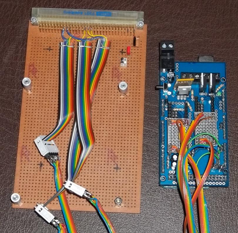
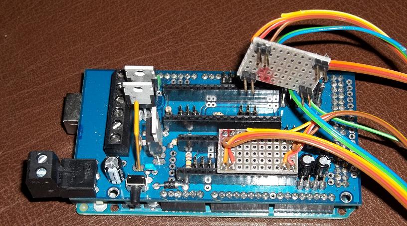
... here are the photos of the RAMPS wired to the interface board.
The adapters for the pololu-sockets are really simple - i have only to connect the pins for GND, STEP and DIR to the corresponding pins in the Interface or for any other stepper driver with this TLL inputs.
The optos/switches are connected by the blue+green wires.
As the 'naked' relative long wires are prone to EMV-disturbances, i'm now assembling another interface board especially for the RAMPS with shielded cables ... and let the old interface board for the Gen3 electronics.
So i can switch easily between the original Isel-Interface and the two Arduinos ... and build another controller with microstepping drivers for a Mendel i'm assembling beside ... and a third controller for a high precision cartesian bot for laser sintering i'm assembling/building too ...
Viktor
--------
Aufruf zum Projekt "Müll-freie Meere" - [reprap.org] -- Deutsche Facebook-Gruppe - [www.facebook.com]
Call for the project "garbage-free seas" - [reprap.org]
|
Generation 7 Electronics Development is now v1.3 July 21, 2011 06:20PM |
Registered: 13 years ago Posts: 7,616 |
Folks,
Generation 7 Electronics is now v1.3: [reprap.org]
Thanks to schmelly, who was the first independent user to get Gen7 v1.3 working.
New features:
Generation 7 Electronics is now v1.3: [reprap.org]
Thanks to schmelly, who was the first independent user to get Gen7 v1.3 working.
New features:
- Supported EDA toolchain is now gEDA 20100929, the one coming with Ubuntu 11.04.
- Use stronger 2 pin, 4 mm connectors (same type as the motors) for the heaters. These match the required currenty much better.
- Remove the MOSFET for the fan. Only few people use a fan. If you're one of them, connect the fan to the PSU directly.
- Remove the I2C header. Was totally unused.
- Make thermistor connectors 2 pin only. The extra pin just caused confusion.
- Replace the ATX20 with an ATX24. The new header is compatible with more recent PC power supply types and accepts ATX20 plugs just fine.
- Use another disk power type connector to supply the heaters. This allows to run a heated bed directly off the Gen7 board, without relays in between. This also introduces the ability to use different voltages for motors and heaters, without making things more complex for casual users.
- MOSFETs are now upright, for better cooling and mounting a heatsink. Also inserted a matching heatsink to the parts list.
| Generation 7 Electronics | Teacup Firmware | RepRap DIY |
|
Re: Generation 7 Electronics Development July 24, 2011 01:54PM |
Registered: 13 years ago Posts: 7,616 |
OK guys, now I have this
No idea what's causing this, but other than this message, uploads still work well. If you encounter this error yourself, it might be an idea to just ignore this message.
avrdude: verification error, first mismatch at byte 0x0000
         0x0c != 0x14
avrdude: verification error; content mismatch
as well.No idea what's causing this, but other than this message, uploads still work well. If you encounter this error yourself, it might be an idea to just ignore this message.
| Generation 7 Electronics | Teacup Firmware | RepRap DIY |
|
Re: Generation 7 Electronics Development July 24, 2011 03:28PM |
Registered: 12 years ago Posts: 137 |
Hi folks,
today I managed to finish my first print ever
As Traumflug mentioned above I'm happy to own one of the first working Gen7 1.3 Boards. However it took me some time to solve a mysterious displacement issue: It seemed a whole set of g-Code commands were not executed at all - my Prusa just did some pauses during the print which ended in whole layers not positioned properly.
It turned out to be an issue with the Teacup firmware I am using: The stepper enable pin was not activated for some g-Codes - they were executed but the motors did not turn. Traumflug was so kind to apply some fixes to the Teacup firmware already. So if you are using a Gen7 Board together with Teacup it's a good idea to upload the latest Gen7 branch revision which can be found here:
Teacup Gen7 branch @ Github
Gen7 templates for Teacup are on the way. Until they are in the repository you can try the ones attached to this thread (containing thermistor configuration for both the Extruder and a Heatbed). Settings are quite conservative but should be a good starting point. An appropriate thermistor table template is attached as well.
best regards,
David
|
Re: Generation 7 Electronics Development July 27, 2011 02:00PM |
Registered: 12 years ago Posts: 17 |
Hi all,
I haven't written here recently, you know, no time for my projects, but now I want to show you latest revision of my Gen7 electronics EAGLE version. I've made many small changes since last revision, traces correction, tidied up silkscreen, additons, etc...
There are also a few additional boards design files, .ps and .pdf for toner transfer (copper and silkscreen layers) and BOM (autogenerated) for every project.
Gen7-EAGLE-07.26.11.zip
Gen7-EAGLE-07.26.11.tar.bz
1. Motherboard.
There are two versions of this design v13 and v14. They aren't in sync with Traumflug version numbers.
v13 version has, like Gen7 v1.2 three MOSFETs and single MOLEX connector for motors and heaters/fan. I've also added additional connectors for +12V line near MOSFET
connectors, ground connectors and 5V connectors near extruder Pololu driver.
v14 version has only two MOSFETs, additional MOLEX connector for heaters and also has additional connectors like v13. Both versions have changed endstops pin allocation, freed ISP pins and used those from MISC header instead. This allows usage of SD card. Added one more I2C connector. And
now, we are free to use all of microstepping resolutions that Pololu drivers offer.
2. Endstops
I've designed two types of endstops, optical and mechanical. Optical uses the same interrupter as Traumflugs, not sure about size but they're very similar. Not tested yet.
Mechanical endstops use lever switch I've bought in local electronics shop.
3. Double Extruder Controller
We can drive only one stepper extruder using Gen7 Motherboard, great, but it may be not enough. Gen3 Extuder Controller is nice board but uses H-Bridge hack to drive stepper motor.
So why not use Pololu drivers? With this board we can drive two additional extruders/something with stepper motor. It has two heater MOSFETs, two temp reading circuits on-board, two places for Pololu driver and RS485 like Gen3 but nothing more.
4. Keyboard
I've designed 4x4 matrix keypad with I2C extender PCF8574 for lower pin usage. Without LCD it's useless I think but I'm waiting for parts to arrive and I'll try to design something for LCD. I don't know if it works but it's good starting point.
5. RS485 Extender
It's tiny board with all required components to communicate using RS485 protocol. Board has 4 RJ45 connectors, SN75176 RS485 driver and 4pin MOLEX connector for powering target boards/devices. RJ45 connector pinout compatible with Gen3.
6. SD Adapter
Like header says it's just a SD card adapter for Gen7 Mainboard with buffer and 3.3V voltage regulator for card on-board. I've desinged this using my connector footprint (not in EAGLE libs) I've bought locally. This design needs adjusting to your connector or buying similar to used here.
Only mechanical endstops were tested, schematic is based on Gen4 endstop so for me it works. All designs are THT easy to make, possibly RepRapable and easy to put together I think
Today (27.07.11) my Pololus arrived, finally. I've also managed to make by toner transfer Mainboard, not etched yet but it looks great. Fifth attempt, now using InkJet photo paper and a bit too small board I've made it. I'll upload some photos after etching and drilling (very beginning of next month). I hope someone will find useful these extensions. I'm open for suggestions. I really appreciate testing.
BTW Nice job guys.
Regards,
Mark
I haven't written here recently, you know, no time for my projects, but now I want to show you latest revision of my Gen7 electronics EAGLE version. I've made many small changes since last revision, traces correction, tidied up silkscreen, additons, etc...
There are also a few additional boards design files, .ps and .pdf for toner transfer (copper and silkscreen layers) and BOM (autogenerated) for every project.
Gen7-EAGLE-07.26.11.zip
Gen7-EAGLE-07.26.11.tar.bz
1. Motherboard.
There are two versions of this design v13 and v14. They aren't in sync with Traumflug version numbers.
v13 version has, like Gen7 v1.2 three MOSFETs and single MOLEX connector for motors and heaters/fan. I've also added additional connectors for +12V line near MOSFET
connectors, ground connectors and 5V connectors near extruder Pololu driver.
v14 version has only two MOSFETs, additional MOLEX connector for heaters and also has additional connectors like v13. Both versions have changed endstops pin allocation, freed ISP pins and used those from MISC header instead. This allows usage of SD card. Added one more I2C connector. And
now, we are free to use all of microstepping resolutions that Pololu drivers offer.
2. Endstops
I've designed two types of endstops, optical and mechanical. Optical uses the same interrupter as Traumflugs, not sure about size but they're very similar. Not tested yet.
Mechanical endstops use lever switch I've bought in local electronics shop.
3. Double Extruder Controller
We can drive only one stepper extruder using Gen7 Motherboard, great, but it may be not enough. Gen3 Extuder Controller is nice board but uses H-Bridge hack to drive stepper motor.
So why not use Pololu drivers? With this board we can drive two additional extruders/something with stepper motor. It has two heater MOSFETs, two temp reading circuits on-board, two places for Pololu driver and RS485 like Gen3 but nothing more.
4. Keyboard
I've designed 4x4 matrix keypad with I2C extender PCF8574 for lower pin usage. Without LCD it's useless I think but I'm waiting for parts to arrive and I'll try to design something for LCD. I don't know if it works but it's good starting point.
5. RS485 Extender
It's tiny board with all required components to communicate using RS485 protocol. Board has 4 RJ45 connectors, SN75176 RS485 driver and 4pin MOLEX connector for powering target boards/devices. RJ45 connector pinout compatible with Gen3.
6. SD Adapter
Like header says it's just a SD card adapter for Gen7 Mainboard with buffer and 3.3V voltage regulator for card on-board. I've desinged this using my connector footprint (not in EAGLE libs) I've bought locally. This design needs adjusting to your connector or buying similar to used here.
Only mechanical endstops were tested, schematic is based on Gen4 endstop so for me it works. All designs are THT easy to make, possibly RepRapable
and easy to put together I think Today (27.07.11) my Pololus arrived, finally. I've also managed to make by toner transfer Mainboard, not etched yet but it looks great. Fifth attempt, now using InkJet photo paper and a bit too small board I've made it. I'll upload some photos after etching and drilling (very beginning of next month). I hope someone will find useful these extensions. I'm open for suggestions. I really appreciate testing.
BTW Nice job guys.
Regards,
Mark
|
Re: Generation 7 Electronics Development July 29, 2011 01:35AM |
Registered: 13 years ago Posts: 7,616 |
Mark,
great effort, really.
However, this is no longer a Generation 7 Electronics. ATmega pinouts don't match, connector pinouts don't match, features don't match, assembly instructions don't match, bill of material doesn't match, etc. etc. For example, it'll be quite confusing to people if you have to tell them "Generation 7 Electronics Endstops" can't be replaced with "Generation 7 Electronics Endstops", because one is the official version and the other is the neonek911 version.
May I suggest you find a new name for your electronics? Like "Pineapple Electronics" or "Wdnesday Electronics"? Also, please rename the files you've distributed so far.
That said, I'll have a look at your additional features, of course. MS1 on the Pololus is missing a pullup/pulldown resistor, with no jumper in place this won't work.
Markus
| Generation 7 Electronics | Teacup Firmware | RepRap DIY |
|
Re: Generation 7 Electronics Development August 10, 2011 04:02AM |
Registered: 13 years ago Posts: 7,616 |
Let's face it: the bootloader currently distributed with Generation 7 Electronics is unreliable.
This bootloader isn't the one from Arduino and is needed for the 20 MHz variants. It works some 95% of the time, so it easily passed all my tests. However, this is no help for the remaining 5%. Yesterday I received the fifth email reporting a non-functional bootloader, so I can no longer ignore that. If the bootloader fails, avrdude, or the Arduino IDE using avrdude, reports something similar to this:
For those without a programmer, I'm currently investigating Martin Thomas' bootloader: [www.siwawi.arubi.uni-kl.de] . Martins code is even cleaner than the current one, is also used in a public project of the c't newspaper and has a veritable changelog, so it should be matured.
Stay tuned, and expect release 1.3.1 soon.
This bootloader isn't the one from Arduino and is needed for the 20 MHz variants. It works some 95% of the time, so it easily passed all my tests. However, this is no help for the remaining 5%. Yesterday I received the fifth email reporting a non-functional bootloader, so I can no longer ignore that. If the bootloader fails, avrdude, or the Arduino IDE using avrdude, reports something similar to this:
avrdude: verification error, first mismatch at byte 0x0000
          0x0c != 0x14
avrdude: verification error; content mismatch
The good thing is, this can be easily fixed with a programmer. Just re-upload the bootloader and it'll work again.For those without a programmer, I'm currently investigating Martin Thomas' bootloader: [www.siwawi.arubi.uni-kl.de] . Martins code is even cleaner than the current one, is also used in a public project of the c't newspaper and has a veritable changelog, so it should be matured.
Stay tuned, and expect release 1.3.1 soon.
| Generation 7 Electronics | Teacup Firmware | RepRap DIY |
|
Re: Generation 7 Electronics Development August 11, 2011 05:37PM |
Registered: 13 years ago Posts: 7,616 |
News on this one.
StevBrennan kindly sent me back his board with a non-functional bootloader for investigation. Funnily enough, neither a fuse nor a byte in the EEPROM nor a byte in flash/program memory has changed. By all my means, this ATmega is identical to a working one.
Any idea what else could change on such a chip? Now I have an example and I'd like to learn the magic before I fix the symptoms and send it back.
| Generation 7 Electronics | Teacup Firmware | RepRap DIY |
|
Re: Generation 7 Electronics Development August 11, 2011 06:03PM |
Admin Registered: 17 years ago Posts: 7,879 |
Maybe an uninitialised variable or register so it works on some chips and not others depending on what state the memory powers up in.
[www.hydraraptor.blogspot.com]
[www.hydraraptor.blogspot.com]


Sorry, only registered users may post in this forum.