My little electronics project over Chrismas and New Year
Posted by majic79
|
My little electronics project over Chrismas and New Year January 19, 2021 02:29PM |
Registered: 10 years ago Posts: 69 |
[github.com]
I'm just going to drop this here and ask what you guys and girls think
[www.nerdsmith.co.uk]
[twitter.com]
I'm just going to drop this here and ask what you guys and girls think
[www.nerdsmith.co.uk]
[twitter.com]
|
Re: My little electronics project over Chrismas and New Year January 26, 2021 07:06PM |
Registered: 10 years ago Posts: 69 |
So I did some validation in LTSpice to try and profile the MOSFET behaviour and discovered that there's no way that it's going to work.
After some research, I finally got a working design at a reasonable cost. I have an excess of board space, so I was able to layout discrete components to solve that power issue. I have a new found respect for electronics designers - I lost a lot of time trying to figure that part out and fortunately, Spice tells me it will work, and as long as there's no glaring issues with the board layout, I think it should be a workable design.
I'm now wondering if I need to add support for a PINDA probe or similar, and I'm wondering if I have enough pins to drive it. Is it just a Z-Stop and a Servo out?
[www.nerdsmith.co.uk]
[twitter.com]
|
Re: My little electronics project over Chrismas and New Year January 28, 2021 12:33PM |
Registered: 12 years ago Posts: 1,450 |
My own personal take on it and for what it is worth: A useful feature on any controller would be a serial interface to subsidiary boards somewhat more complex than simple digital pins for Z probes and other things.
Examples of external controller boards that I am playing with and which are limited to simple digital IO are:
These controller boards are all very simple and all use PIC16 MCUs; It would obviously be useful to have some form of serial communication such as RS485 so that they could actively have parameters changed. I2C and SPI can be forced to work for this sort of application but they are not really at their best over distances longer than a few hundred mm. Most other serial interfaces need supporting electronics.
At the moment my host controller is an Arduino Mega 2560 with a RAMPS 1.4 which do the job acceptably but trying to add serial communications to a number of other boards seems to be a bit above its pay grade.
Mike
Examples of external controller boards that I am playing with and which are limited to simple digital IO are:
- A toggle motor for swapping two print heads. The control board has an input with high selecting one head and low selecting the other. A single output is used from the toggle motor control board which is asserted on completion of a move.
- An under-bed probe detects nozzle contact for each probe to set nozzle height. The control board is able to detect "soft" contacts indicating the presence of plastic on the tip. Two outputs only, contact detected and contact was good.
- A touch contact probe to perform the function of bed leveling. This works somewhat like a BLTouch but also checks for baseline drift or mechanical or electrical noise which would reduce the precision of the detected touch. This again uses two outputs, one for the contact detection and one to be interogated before the z-probe operation to find if the baseline is good.
- A device to measure the cross-sectional area of the feedstock filament. This works by measuring the acoustic back-pressure offered by an orifice through which the filament passes. The output is an analog value.
These controller boards are all very simple and all use PIC16 MCUs; It would obviously be useful to have some form of serial communication such as RS485 so that they could actively have parameters changed. I2C and SPI can be forced to work for this sort of application but they are not really at their best over distances longer than a few hundred mm. Most other serial interfaces need supporting electronics.
At the moment my host controller is an Arduino Mega 2560 with a RAMPS 1.4 which do the job acceptably but trying to add serial communications to a number of other boards seems to be a bit above its pay grade.
Mike
|
Re: My little electronics project over Chrismas and New Year January 28, 2021 12:45PM |
Registered: 10 years ago Posts: 69 |
I2C is the easiest to add there, it only needs 2 pins (I have 4 free) and as you say, you need to keep it nearby. If the signal is not too far away you could keep the electronics in range of the board and then just deal with mounting the sensor and routing the wiring. For probing, you could sync the query over the serial bus before stepping - might slow things down a bit, but that seems an acceptable price to pay.
I like the idea, I'll see if I can add it. It would also solve my consideration about how to add support for probes!
Thank you!
[www.nerdsmith.co.uk]
[twitter.com]
I like the idea, I'll see if I can add it. It would also solve my consideration about how to add support for probes!
Thank you!
[www.nerdsmith.co.uk]
[twitter.com]
|
Re: My little electronics project over Chrismas and New Year January 28, 2021 02:35PM |
Registered: 12 years ago Posts: 1,450 |
Quote
majic79
.................................................................................. For probing, you could sync the query over the serial bus before stepping - might slow things down a bit, but that seems an acceptable price to pay.
.......................................
Thank you!
As long as response times can be in the low millisecond region. I use a probe speed of 2mm per second on my piezo probes which equates to an approach speed of 2 microns per millisecond. At this speed, a 10ms latency would only be 20 microns and fairly reasonable. Having said that, some people seem to use approach speeds for touch sensors in the region of 25mm/second in the belief that piezo and FSR sensors need a good thump. This would give a potential error of 0.25mm
Mike
|
Re: My little electronics project over Chrismas and New Year January 28, 2021 04:39PM |
Registered: 10 years ago Posts: 69 |
A simple register protocol over I2C should do the trick - sending a 1 to enable the monitoring and then polling for the feedback once the stop is hit is going to be pretty fast. at 400KHz (I2C Fast mode) you're looking at 20 microseconds for that communication to occur (assuming 10 bits of data - enables, addresses, response, stop bit). You could stack or daisychain the boards to add more on seperate addresses - so there could be some round-robin latency if you have to query the state of more than 5 items, that may run to 1ms or so. I don't imagine that you would want to have too many items in that stack anyway for probing, so I think this could be workable.
I'm breaking out 5V for power, but I'm thinking about breaking out the 3.3V Vdd of the MCU - the pins aren't 5V tolerant, so there needs to be some level shifting going on. If I break out 3.3v, then there are a few options for any expansion boards.
Edited 2 time(s). Last edit at 01/28/2021 06:32PM by majic79.
[www.nerdsmith.co.uk]
[twitter.com]
|
Re: My little electronics project over Chrismas and New Year January 28, 2021 06:49PM |
Registered: 10 years ago Posts: 69 |
I've pushed an update up including the I2C interface after a little reshuffling.
[www.nerdsmith.co.uk]
[twitter.com]
[www.nerdsmith.co.uk]
[twitter.com]
|
Re: My little electronics project over Chrismas and New Year January 29, 2021 02:09PM |
Registered: 12 years ago Posts: 1,450 |
I will monitor your progress with interest as my piezo conditioning boards were originally intended to work with an I2C for changing parameters - this is still provided for on the PCB [workspace.circuitmaker.com] although I have not used it yet.
An additional question, What firmware will you be using?
Mike
An additional question, What firmware will you be using?
Mike
|
Re: My little electronics project over Chrismas and New Year January 29, 2021 03:13PM |
Registered: 10 years ago Posts: 69 |
I'm quite tempted to use a piezo sensor, so I'm open to a collaboration on that. Planning to use Marlin as that's the firmware I've got the most experience with and there's already support for the processor. My biggest concern is the arduino library, but there's plenty of capacity in flash, so it may not be too much of an issue.
I'll take a look at your project - would be good to at least get support for an I2C Probe
[www.nerdsmith.co.uk]
[twitter.com]
I'll take a look at your project - would be good to at least get support for an I2C Probe
[www.nerdsmith.co.uk]
[twitter.com]
|
Re: My little electronics project over Chrismas and New Year January 30, 2021 06:25AM |
Registered: 12 years ago Posts: 1,450 |
I will give what assistance I can, but don't expect too much as the world is too full of Lurgies and Boojums (disease and misfortune), not to mention the apathy that has laid waste to the RepRap forum and the ravening Dunning-Kruger syndrome which bestrides the world like a colossus. As herd immunity to none of the above has been achieved I may fall victim at any moment.
I have some spares of the Piezo14 board from earlier work where I needed to run a number in parallel. If you have or can acquire a PicKit3 or PicKit4 I could send you one.
Mike
I have some spares of the Piezo14 board from earlier work where I needed to run a number in parallel. If you have or can acquire a PicKit3 or PicKit4 I could send you one.
Mike
|
Re: My little electronics project over Chrismas and New Year January 30, 2021 07:32AM |
Registered: 10 years ago Posts: 69 |
Sorry, only got a PicKit2 and an Atmel ICE - since microchip bought atmel, is there crossover support ow?
I've not touched a Pic for about 5 years, so I fear I'm a bit behind on their tech.
[www.nerdsmith.co.uk]
[twitter.com]
I've not touched a Pic for about 5 years, so I fear I'm a bit behind on their tech.
[www.nerdsmith.co.uk]
[twitter.com]
|
Re: My little electronics project over Chrismas and New Year January 30, 2021 07:52AM |
Registered: 12 years ago Posts: 1,450 |
I am fairly sure that the PicKit2 won't program the PIC16F1704 MCU that I use on these boards. There are very cheap clones available on Ebay but I don't know them so can't recommend either way.. I also can't say if the Atmel ICE will work.
As far as Microchip itself goes, they do a fairly good free C compiler but their support for assembler is pretty stinky - annoying for me as I do useful work in assembler but am distinctly handicapped in high-level languages.
Mike
As far as Microchip itself goes, they do a fairly good free C compiler but their support for assembler is pretty stinky - annoying for me as I do useful work in assembler but am distinctly handicapped in high-level languages.
Mike
|
Re: My little electronics project over Chrismas and New Year January 30, 2021 02:25PM |
Registered: 4 years ago Posts: 285 |
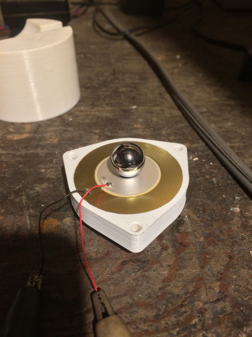
@leadinglights, for what it's worth I've also been working on an underbed piezo sensor for my delta printer. I noticed that automotive piezo knock sensors use a ring shaped piezo element, with a quite heavy mass glued to them, so they act as more of a seismograph than a microphone. I ground a small flat spot in a 1/2 inch diameter stainless steel ball, and JB-Welded it to the center of a standard Murata 41 mm diameter piezo disc, which feeds a MicroChip 12F1840 ADC input (with very simple clipping and low pass filtering). The results are pretty astounding. It is almost immune to acoustic input (like motor vibration and air horns), but will detect a BB dropping 2 inches onto the bench 4 feet away.Quote
leadinglights
Quote
majic79
.................................................................................. For probing, you could sync the query over the serial bus before stepping - might slow things down a bit, but that seems an acceptable price to pay.
.......................................
Thank you!
As long as response times can be in the low millisecond region. I use a probe speed of 2mm per second on my piezo probes which equates to an approach speed of 2 microns per millisecond. At this speed, a 10ms latency would only be 20 microns and fairly reasonable. Having said that, some people seem to use approach speeds for touch sensors in the region of 25mm/second in the belief that piezo and FSR sensors need a good thump. This would give a potential error of 0.25mm
Mike
So the trick is to mass load the center of the piezo disc, and support the disc only at its outer rim. No clamps, levers, etc. Just thought this might be of interest.
Edited 1 time(s). Last edit at 01/31/2021 01:51PM by rq3.
|
Re: My little electronics project over Chrismas and New Year January 30, 2021 04:16PM |
Registered: 12 years ago Posts: 1,450 |
Although I used to use under-bed piezo sensors, I have started looking for better ways after discovering that there were chaotic effects that made some spots relatively insensitive. You can minimize, but not eliminate this effect by having 3 or more sensors right on the outer periphery of the bed. You can see this effect visually if you look up Chladni plates on YouTube. A report on the experiments where I found how severe this effect could be at [reprap.org]
To put a picture in a forum entry:
Select Attach a file
Click on the "Browse" button. This will allow you to select your file on the computer
Once it shows next to the "Browse" button click on the "Attach" button
Now it will show your file name with two more buttons. Navigate to where you want the picture to show in your editing panel and click, then click on the "Create link in message"
When you want to preview your message and the picture, the picture will typically not appear but should show when you click the "Preview" button a second time.
This picture attached by that method
Good luck,
Mike
To put a picture in a forum entry:
Select Attach a file
Click on the "Browse" button. This will allow you to select your file on the computer
Once it shows next to the "Browse" button click on the "Attach" button
Now it will show your file name with two more buttons. Navigate to where you want the picture to show in your editing panel and click, then click on the "Create link in message"
When you want to preview your message and the picture, the picture will typically not appear but should show when you click the "Preview" button a second time.
This picture attached by that method

Good luck,
Mike
|
Re: My little electronics project over Chrismas and New Year January 31, 2021 01:53PM |
Registered: 4 years ago Posts: 285 |
Sorry, only registered users may post in this forum.