New threaded rod driven arm
Posted by galaxyman7
|
New threaded rod driven arm April 02, 2010 02:43AM |
Registered: 14 years ago Posts: 198 |
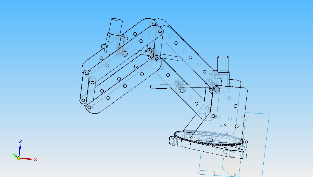
Hey, I have thought about the gear design, and I have decided it is too much trouble both to make it work and to maintain accuracy. Therefore I have changed the design to something much simpler, a threaded rod driven arm. The way it works is this:
There is a pivoting holder for the nut on one parts of the frame
There is a pivoting holder for the motor on another part
They are connected by threaded rod, when the motor turns, the two points get closer together or move apart.
When the points change distance, the arm rotates.
This seems much simpler than all the gears and much more accurate.
The last gear to get rid of is the base. I need to find an easy way to drive the base using threaded rod.
A picture of the new experimental design is attached.
|
Re: New threaded rod driven arm April 05, 2010 03:42AM |
Registered: 16 years ago Posts: 900 |
Take a look at the work that has been done re cutting your own worm gears they are surprisingly easy. Wade, Nophead, Bodgit and Myself have done some on this an published the work.
Admitedly for feeding filament but they are exactly the same. Google worm gears too that is where I originaly got the ideas from.
Necessity hopefully becomes the absentee parent of successfully invented children.
Admitedly for feeding filament but they are exactly the same. Google worm gears too that is where I originaly got the ideas from.
Necessity hopefully becomes the absentee parent of successfully invented children.
|
Re: New threaded rod driven arm April 07, 2010 12:19PM |
Registered: 14 years ago Posts: 198 |
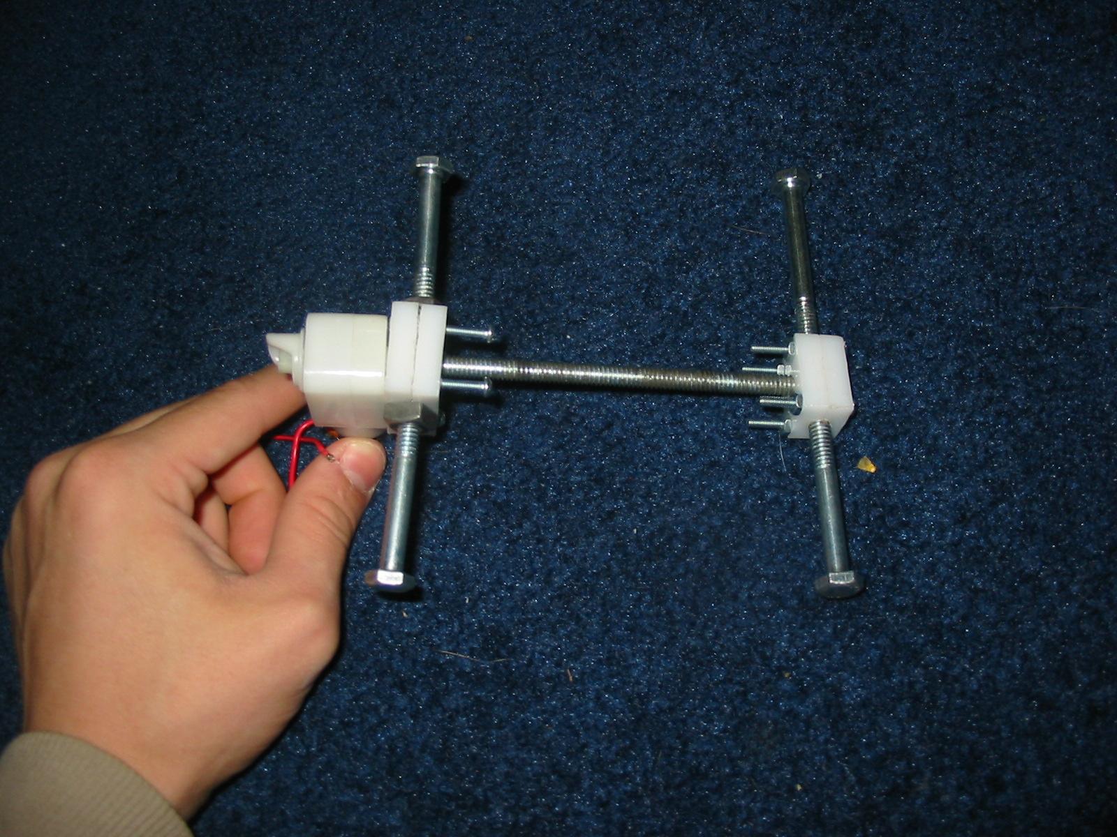
Here is a picture of the motor connected to the threaded rod, which is threaded through a nut with a holder around it. Both the motor and nut have bolts coming out from each side. These are to let them pivot.
|
Re: New threaded rod driven arm April 08, 2010 07:35PM |
Registered: 14 years ago Posts: 105 |
|
Re: New threaded rod driven arm April 09, 2010 04:45AM |
Registered: 14 years ago Posts: 198 |
The nut and motor holders are made from HDPE on my cnc milling machine. The acrylic sides are also made on the cnc. However, polypropylene is much cheaper and I will probably switch to that.
Right now I am trying to come up with a way to calculate the sag of the arm depending on the angles of the joints. The program can then compensate. I am also looking into how to calculate the oscillation of the arm on a quick stop. This way I can compensate for that also, and hopefully let the arm take sharper, faster turns.
I plan to make a program in game maker that can take user inputs, such as the arm length, and the type of plastic used, and then create gcode that is specially tailored for that machine.
This way, even if you use flimsy plastic, the program could theoretically make the machine extremely accurate by compensating for everything.
|
Re: New threaded rod driven arm April 09, 2010 04:59AM |
Registered: 14 years ago Posts: 198 |
For the motor control, I will be using an SX chip from parallax
[www.parallax.com]
, plus 4 of these Hbridge driver chips.
[search.digikey.com]
4 of these photo interrupters
[search.digikey.com]
And 4 acrylic disks with contact paper with printed pinstripes on them. (100 per rev)
I am not sure if the contact paper will be transparent enough, but it is worth a shot.
The SX will interface with the parallel port, taking step and direction signals and moving the motors accordingly. One guy has actually designed a circuit to convert usb to parallel, to be used with cnc. check it out here.
[www.cncdudez.co.uk]
It will also need some limit switches, to calibrate the arm.
I don't think the temperature of the plastic really needs to be controlled by computer. That can be set manually.
Add it all up, and it comes out to around 40 dollars total! (not including shipping)
Edited 2 time(s). Last edit at 04/09/2010 05:07AM by galaxyman7.
|
Re: New threaded rod driven arm April 15, 2010 10:58PM |
Registered: 15 years ago Posts: 3 |
Hi,
I did a lot of work on something very similar to your original arm. I first tried laser cut gearing, but it was too weak. I then tried just making it ultra light and running the joints directly from the gear motors. They weren't strong enough. The next try was going to be using drive screws very similar to what you are doing. Then I had to table the whole thing.
I'm in Indonesia now. I'll be back sometime in June. I think I will purchase a laser cut mendel kit and then start working on the arm again sometime in August. I'd love to keep up on your work and collaborate with you in the future.
-Brian
[builders.reprap.org]
brian dot korsedal at gmail dot com
|
Re: New threaded rod driven arm April 21, 2010 02:30PM |
Registered: 14 years ago Posts: 198 |
|
Re: New threaded rod driven arm April 21, 2010 06:06PM |
Registered: 14 years ago Posts: 278 |
|
Re: New threaded rod driven arm May 20, 2010 04:29AM |
Registered: 14 years ago Posts: 198 |
|
Re: New threaded rod driven arm July 04, 2010 04:58PM |
Registered: 14 years ago Posts: 198 |
Ok, I am finally ready to work on this thing. I made the arm and changed the x axis to threaded rod. The whole arm slides on two rails. The rails can be however long you want, allowing for a huge print area. The problem is friction with the rails on the plywood. The plywood alone on the rails is not slippery enough even with grease. Therefore I have bought a couple of very cheap teflon lined bearings to slide along the rails. You can get them here, 5 for $0.48 !!
amazon
I have also gotten almost all of my materials from this seller, and you can get free shipping for $25 or over.
I have also gotten a couple 1" dia ones for my cnc. If they work, this will be so much cheaper and better than the linear bearing designs.
Anyways, I have also uploaded some pics of the arm and slide assembly. Now I am just working on the couplers for the motors to the threaded rod.
|
Re: New threaded rod driven arm July 05, 2010 04:40PM |
Registered: 16 years ago Posts: 900 |
Wow that s one of the most innovative things I have seen in a while.
Questions:-
Why slide the arm up and down an axis. Keep the arm stationary and make the bed a conveyor bed. Endless build space and automatable dump of completed objects......
Great ideas keep it up....
Necessity hopefully becomes the absentee parent of successfully invented children.
Questions:-
Why slide the arm up and down an axis. Keep the arm stationary and make the bed a conveyor bed. Endless build space and automatable dump of completed objects......
Great ideas keep it up....
Necessity hopefully becomes the absentee parent of successfully invented children.
|
Re: New threaded rod driven arm July 05, 2010 10:02PM |
Registered: 14 years ago Posts: 198 |
|
Re: New threaded rod driven arm July 06, 2010 02:18AM |
Registered: 16 years ago Posts: 900 |
Consider a conveyor a little like the one Charles Pax was working on.
There is a feed roller at either end and the conveyor belt wrapping around the roller acts to peel the belt from the underside of a flat object. It cant curve around the roller with the belt.
I guess combining this with a clever off ramp/scraper gives a rudimentary auto eject for completed components.
The difficult bit no one has sorted adequately yet is heated bed and anti warp conveyor belt. Although there have been some brave attempts that have advanced the state of play quite a bit.
Necessity hopefully becomes the absentee parent of successfully invented children.
|
Re: New threaded rod driven arm July 07, 2010 06:26PM |
Registered: 14 years ago Posts: 198 |
|
Re: New threaded rod driven arm July 08, 2010 03:06AM |
Registered: 16 years ago Posts: 900 |

|
Re: New threaded rod driven arm July 08, 2010 05:04PM |
Registered: 14 years ago Posts: 380 |
galaxyman,
way cool looking! I may have to steel some of those ideas for my underwater ROV!
Suggestions: I really like the Digikey L298 dual H bridge motor drivers instead of the BD6221Fs . It handles up to 2 amps on either motor, over a wider voltage range. And you can still get it in through hole, if that is what you prefer.
If you use a left handed thread for one rod and a right handed thread for the other, and metal gears at the end, then when you rotate both the same amount, the top and bottom traveling nuts the hold the base of you arm will move while remaining perfectly vertical. You already have the matched, parallelogram linkages to keep the wrist end perfectly level, it would make sense to make the base always stay level, too.
Put the first motor on the back side of the horizontal rods to counterbalance the weight of the arm. You have the 'shoulder joint' square, with the pivot bolts for each arm level with the horizontal rods. Offset them, so that the top piece is well above the rods and the bottom piece exactly in between them. This way the upper arm segments can both be extended out past the other side of the rods. Placing the first, biggest motor and linkage here will balance the arm extending out the other side, and reduce sagging. Also, use blocks of aluminum for the end supports. They are stronger than the plywood, and the weight of the arm, holding something at full extension will try to twist the rods. The end pieces need to be very stout, and well connected to a substantial base plate.
Looks VERY exciting!
Mike
|
Re: New threaded rod driven arm July 11, 2010 11:48PM |
Registered: 14 years ago Posts: 198 |
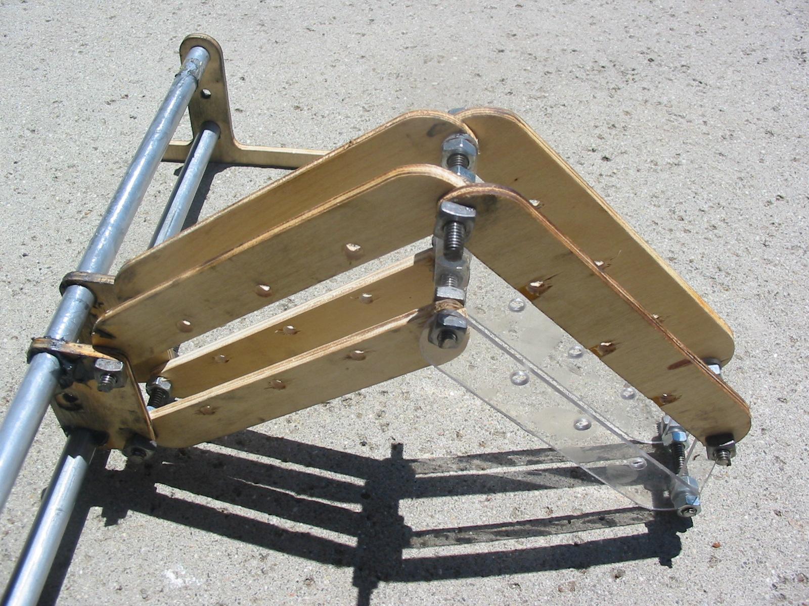
I like the counter-balance idea. I might even put a weight in addition to the motor. As for the twisting of the arm, that is why I have threaded studs between the two sides of the arm. These studs have nuts between the two sides as well as on the outside. When you tighten them, it fixes the distance and makes sure the two sides stay parallel, preventing twisting. I might even add washers to make it even more sturdy and less likely to twist.
I think the Hbridge driver chips should be fine. I am using small motors at 12 V that only draw 0.5 A at stall. I do wish the ones I am using were through hole though. SMD should be fairly easy to solder for me since i have the right tools, but difficult for others who do not.
The base will always stay level because it slides on two parallel rails. I don't need any gearing system to do that.
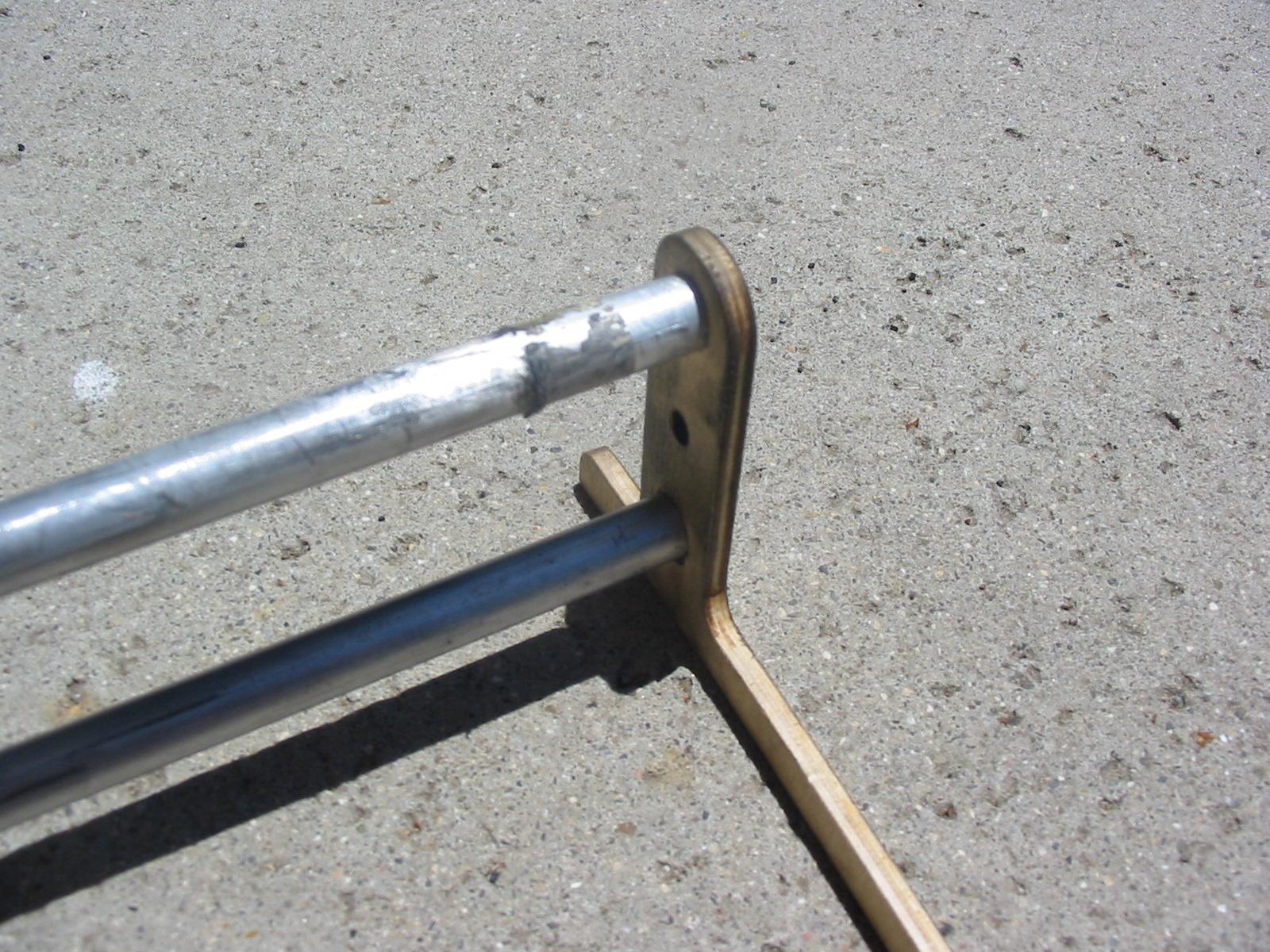
The end supports should be fine. I am using two offset pieces of plywood bolted together for each end. The picture is not the finished design. As long as the base is wide enough, the arm should not tip over.
I just got a slip in the mail that said my package is at the post office, so I will get the linear slides and other stuff tommorow. I really hope these things work because I really hate trying to make my own.
I think the Hbridge driver chips should be fine. I am using small motors at 12 V that only draw 0.5 A at stall. I do wish the ones I am using were through hole though. SMD should be fairly easy to solder for me since i have the right tools, but difficult for others who do not.
The base will always stay level because it slides on two parallel rails. I don't need any gearing system to do that.
The end supports should be fine. I am using two offset pieces of plywood bolted together for each end. The picture is not the finished design. As long as the base is wide enough, the arm should not tip over.
I just got a slip in the mail that said my package is at the post office, so I will get the linear slides and other stuff tommorow. I really hope these things work because I really hate trying to make my own.
|
Re: New threaded rod driven arm July 16, 2010 12:11AM |
Registered: 14 years ago Posts: 198 |
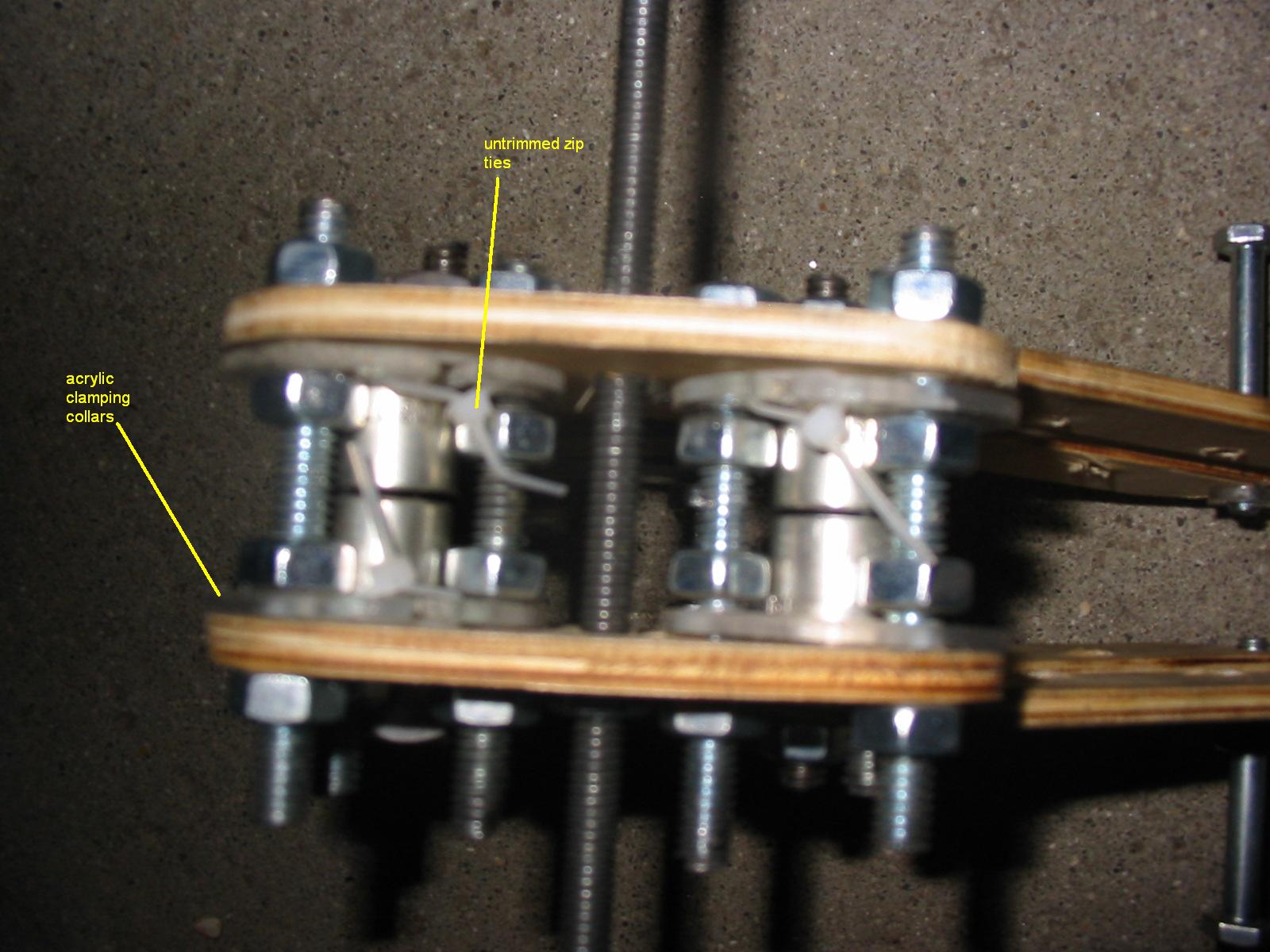
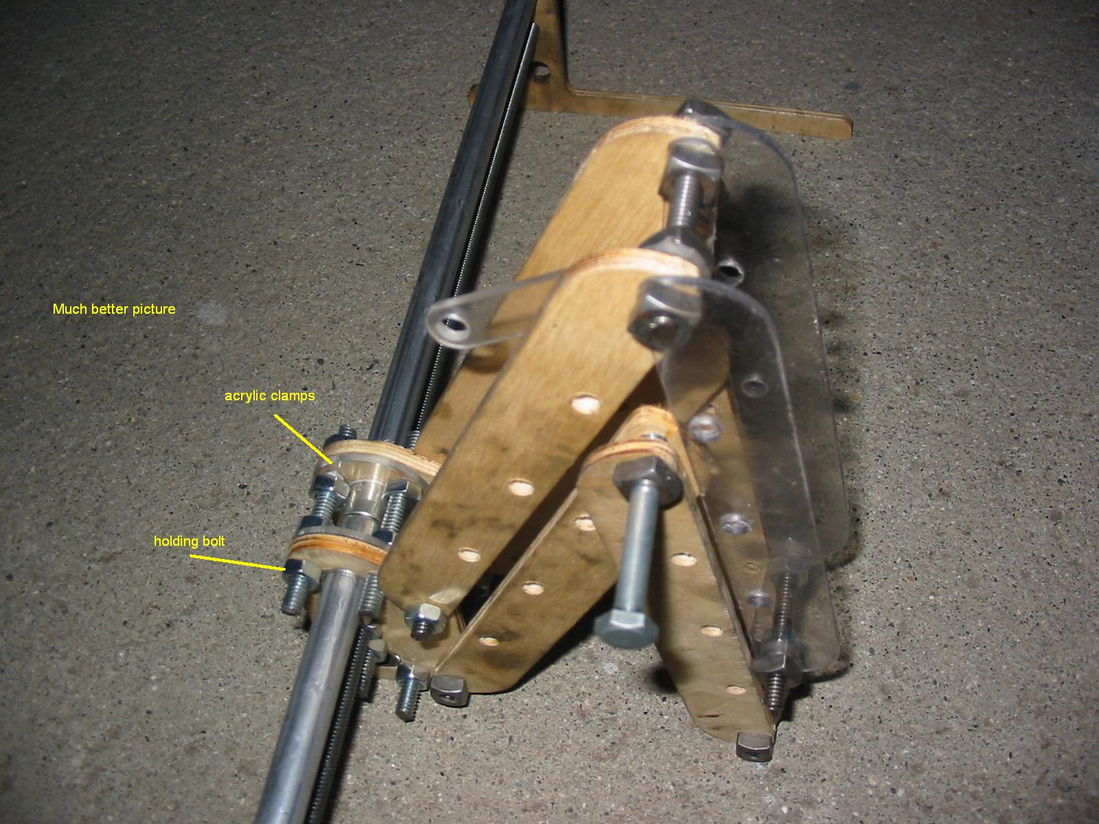
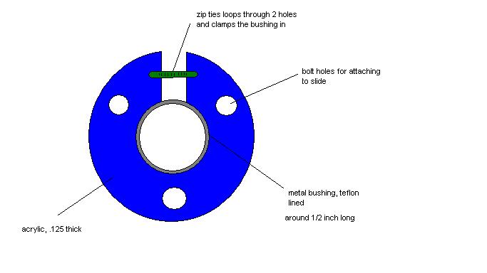
Ok, the teflon lined bushings work great. I just made a few plastic clamping rings with holes around the edge, and then forced each slide into the holes. Then I used zip ties to hold the clamping rings tight. I bolted the clamping rings to the frame, and voila, you have a very low friction slide.
It is hard to explain how it works so I uploaded some pictures along with sketches.
It is very smooth, and I can push it back and forth with my finger easily.
The only thing is one of my rails turned out to be just a little over 1/2 inch, so I will have to take a bushing to the store and find a nicely sized rail.
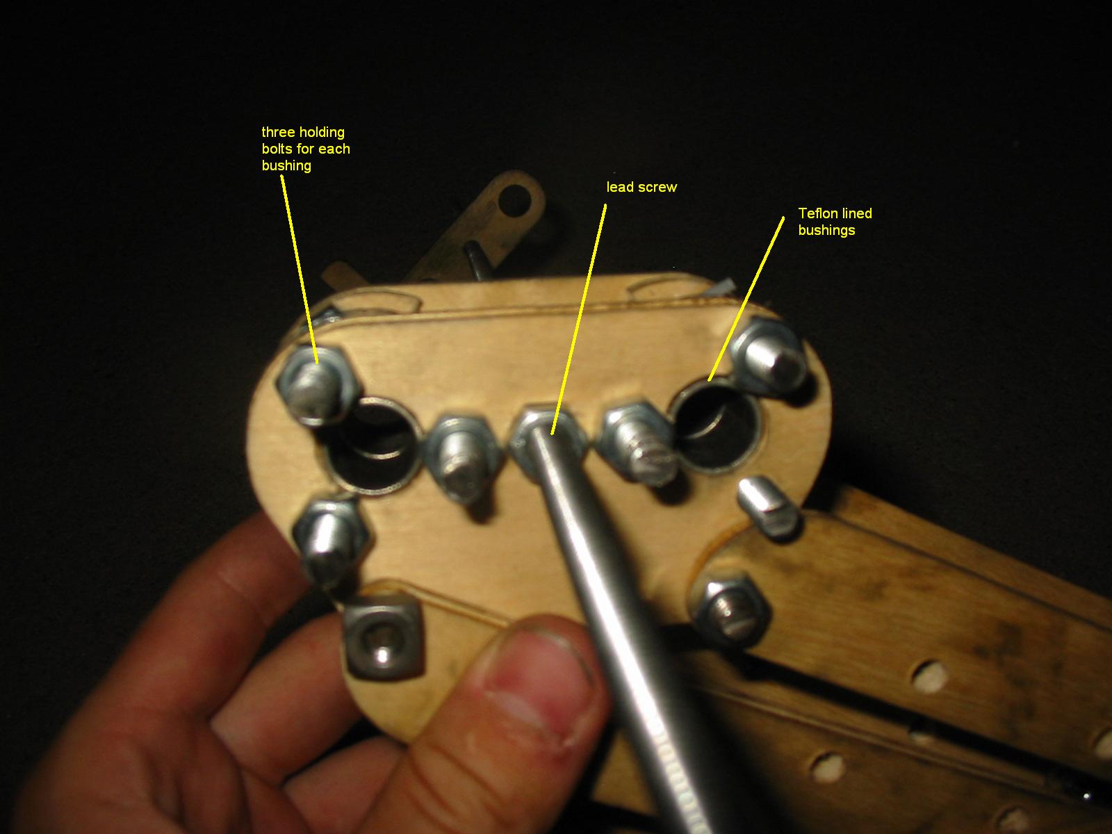
The two nuts that go over the lead screw are recessed in a hexagonal hole in the side of the slide. I hope they will not come out, because then I would need to redesign the slides.
Other than that, I am working on designing the circuit for the driver board, along with trying to learn the programming language for the SX microcontroller. So I have a lot to do, but I think the linear slides and lead screw are the biggest issues (speaking from experience with my CNC).
It is hard to explain how it works so I uploaded some pictures along with sketches.
It is very smooth, and I can push it back and forth with my finger easily.
The only thing is one of my rails turned out to be just a little over 1/2 inch, so I will have to take a bushing to the store and find a nicely sized rail.
The two nuts that go over the lead screw are recessed in a hexagonal hole in the side of the slide. I hope they will not come out, because then I would need to redesign the slides.
Other than that, I am working on designing the circuit for the driver board, along with trying to learn the programming language for the SX microcontroller. So I have a lot to do, but I think the linear slides and lead screw are the biggest issues (speaking from experience with my CNC).
|
Re: New threaded rod driven arm July 16, 2010 01:37AM |
Registered: 16 years ago Posts: 900 |
|
Re: New threaded rod driven arm August 05, 2010 02:43AM |
Registered: 14 years ago Posts: 198 |
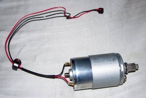
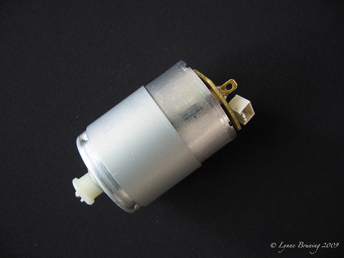
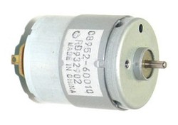
Ok I have been working on stuff, and I just got a bunch of motors out of a printer. I got a big one for the x axis, and a couple small ones for the arm. (similar motor pics attached) The problem is connecting the motors to the threaded rod. I have tried making couplings on my CNC out of plastic, but the set screws just strip the plastic. I have also tried clamping two plastic pieces around a shaft, but the threaded rod slips. It is hard to get the coupler to stay on without stripping or slipping. My next idea is to grind the threaded rod down and make a flat edge for it to grab onto. However, I know it will be hard to get the alignment right when you do this. Has anyone else had experience making couplings from plastic? I need something easy to mill out and sturdy so I don't have to keep replacing it.
|
Re: New threaded rod driven arm August 05, 2010 04:14AM |
Registered: 16 years ago Posts: 900 |
I am just making some couplings myself but from brass (rod but a brass scfrew or bolt could be used instead.
I am turning the coupling on the lathe so that the motor end is a hot fit ie it needs to be heated before sliping over the motor shaft. when cool there is no chance of slipage.
The threaded rod end i am threading so thhat the threaded rod screws in and is locked using thread locking compound and a lock nut.
dunno if this helps any.
cheers aka47
Necessity hopefully becomes the absentee parent of successfully invented children.
|
Re: New threaded rod driven arm August 05, 2010 01:54PM |
Registered: 14 years ago Posts: 105 |
My instinct would be to drill and bottom tap brass rod and then press fit the other size that isn't tapped on to the shaft. Cross section should look like an extruder nozzle with a bigger hole.
I wouldn't worry about zero backlash couplings for now. The benefits don't merit the complexity in the prototyping stage, although eventually: it will be low hanging fruit for picking up tighter accuracy.
I wouldn't worry about zero backlash couplings for now. The benefits don't merit the complexity in the prototyping stage, although eventually: it will be low hanging fruit for picking up tighter accuracy.
|
Re: New threaded rod driven arm August 05, 2010 03:42PM |
Registered: 14 years ago Posts: 198 |
Unfortunately I do not have a lathe, just a drill press and a home made cnc. I have some aluminum bar stock, but making a coupler with a drill press has proved to be impossible. The alignment is always off, and the drill bit constantly gets stuck in the aluminum. I was wondering if there would be an easier method using HDPE plastic, which I happen to have tons of. Preferably something I can mill out. I think I will try grinding the threaded rod today, and make a clamp type coupler out of plastic. If that fails I can always drill a hole through the threaded rod and insert a pin to keep it from slipping. I am trying to think outside the box here, since couplers will eventually be rep rapped also.
|
Re: New threaded rod driven arm August 05, 2010 07:26PM |
Registered: 16 years ago Posts: 900 |
I understand the issues with having CNC and no lathe.
You can approximate a lathe with a Drill Press (Pillar Drill) or CNC Milling setup.
You clamp the lathe/drill bits on the bed/vice and put the brass rod (or hex brass rod) into the chuck.
Position the drill bits and or lathe tools correctly and you can drive the spinning workpiece onto the tool in a lathe like fashion.
Notes:-
It can be noisy and you often get funny resonance things happening if the tool lengths (the length of clamped tool piece extending out of the clamp/vice) are over long. Keep them as short as possible.
Also use lots of lubricant 3in1 oil or wd40 will do at a push if you don;t have cutting compound.
Aluminium can be a bitch to work with.
A. it work hardens and can suddenly screw up mid piece.
B. it is very soft and clogs the cutting edge of the cutting tool (drill bit or lathe tool is irrelevant).
To fix B make sure the cutting tool is always sharp and frequently withdraw the tool from the operation and clean off the swarf and junk that accumulates over the cutting edge making it blunt and graby on the work piece.
It is doable with care.
I have done this.
It is less than optimal but in a tight corner will do the job.
Think outside of the box.
Necessity hopefully becomes the absentee parent of successfully invented children.
|
Re: New threaded rod driven arm August 06, 2010 05:36AM |
Registered: 14 years ago Posts: 105 |
Plastic would work.
Just a mill might be enough. Particularly if you have CNC and a dial indicator or edge finder.(It sounds as though you may not have the desired accessories/tooling?)
If you can clamp round stock in a pin vise, or V-Block you can use an edge finder or indicator to find it's center.
Once the part is centered: a center cutting end mill can be used to plunge cut. A CNC mill can be used to do a helical interpolation, or a rotary table can be used to do circular interpolation.
Otherwise: an offset boring head could be attempted, or even a drill bit. The conical bottom of the hole will do a good job of centering your smaller drill bit for the motor shaft.
Kerosene is god's gift to aluminum as a lubricant. Aluminum's theoretical cutting speed is ~1600/(rotating diameter)=RPM
In practice: to get a good finish, you may have to go slower if: the setup isn't rigid, your cutter isn't sharp, or some other source of chatter is causing a squeel.
It doesn't hurt to go slower assuming that you can feed slow & steady enough to not break the drill bit, but that's a big assumption with small diameter drill bits on deep holes. Small bits need high RPMs because they can't handle much of a chip load. Without high RPMs: it's difficult to feed slow enough to keep them happy.
If the flutes clog with chips: it will cause the drill bit to break, so it's important to "peck" at deep holes.
In a pinch you can use an endmill as an edge finder, by either visually watching for contact with the material with the spindle on, or more recklessly: the same way you touch-off a tool's length.
By zeroing your dials on one side of a round part, touching off on the other side, and dividing the difference in half: you can back up by 1/2 the difference and be centered in one axis. Then you can center in the other axis in the same way.
Another option would be to ignore center & chuck the finished product to your spindle using the drill shaft hole, and a mandrel.
Then you could chuck a lathe bit in a vise and use the table and the Z axis to turn the part concentric.(Ideal for balance reasons I guess.)
Hopefully some of this was helpful. I'm kind of rambling cause I don't know the source of your problem.
|
Re: New threaded rod driven arm August 07, 2010 01:43AM |
Registered: 14 years ago Posts: 198 |
Unfortunately my Cnc is home made, made out of mdf. When milling aluminum it is horribly inaccurate and aluminum sticks all over the bit. I could try coolant but that still does not affect the accuracy. One problem is holding the aluminum bar when drilling into it. It almost always catches on the bit and gets stuck, spinning around. I do not have an edge finder, and so it is hard to find the exact center. It just seems like a huge hassle for such a simple thing.
I just milled a plastic clamp coupler today, and I used a screw that went through the threaded rod to keep it on. That worked great, however, the motor shaft keeps slipping out no matter how tight I clamp it. I just want to find a design anyone could make with a reprap and not have special tools like a lathe or drill press. The problem is the hdpe is too slippery. I was thinking 2 part epoxy might work to keep the coupler on the shaft. Do you think this will work?
I just milled a plastic clamp coupler today, and I used a screw that went through the threaded rod to keep it on. That worked great, however, the motor shaft keeps slipping out no matter how tight I clamp it. I just want to find a design anyone could make with a reprap and not have special tools like a lathe or drill press. The problem is the hdpe is too slippery. I was thinking 2 part epoxy might work to keep the coupler on the shaft. Do you think this will work?
|
Re: New threaded rod driven arm August 07, 2010 05:08AM |
Registered: 16 years ago Posts: 900 |
|
Re: New threaded rod driven arm August 08, 2010 02:30AM |
Registered: 14 years ago Posts: 198 |
I have not tried that yet, and that is probably a good idea. I was thinking of using a piece of 1/8" ID, 1/4" OD tubing to cover the 1/8 motor shaft. Then using a 1/4 ID, 3/8 OD tubing to connect to the threaded rod. Do you know where to get very small clamps? I have looked but only found ones for larger hoses.
And by the way, I did get the plastic coupler to work, but I have a feeling the set screw holding the motor shaft in place will strip out the hole. I tried the large motor on the x axis, with mixed results. The motor worked fine in the middle section of the rails, but when it got to the outsides, it started to get hard to turn the rod. I don't know if it is binding, or if the threaded rod is messed up in some places. I did the end supports with my CNC, so I doubt the distance between the rails changes. I will try taking the rails off and running the threaded rod through the nuts, just to make sure it isn't messed up in any places. The motor has enough torque to get it through the middle section, and when it is in that section, the arm can go around 30 ipm without any problems. This is excellent, but if I cannot find the problem I might have to gear the motor down to get some more torque out of it.
Another problem is vibration. I think it is because of the coupler, which is not balanced. Hopefully the rubber tubing will work and lessen the vibration.
I also have to redesign the mounts for the motors on the arm. They need different mounting holes than the gm3 motors.
In summary, things look pretty good. If I attach the other printer motors to the arm, this thing should have tons of speed. I think since I don't have an extruder yet, I will use it as a plotter to test it out. Soon I will upload some drawings and stl / stp files so you guys can check my work, and maybe make one of your own!
Edit: Made a wiki here [reprap.org]
Haven't edited a wiki before so if you guys could help me out and put some of the pics in, that would be great.
Edited 1 time(s). Last edit at 08/08/2010 03:06AM by galaxyman7.
|
Re: New threaded rod driven arm August 11, 2010 10:25PM |
Registered: 14 years ago Posts: 198 |
Have you guys seen the TI Launch Pad? I can't believe how cheap it is. I am sure this is going to be what everyone uses now. I still have my Parallax board, so I will use that for the robot arm, but in the future the Launch Pad is my first choice.
Anyways, I have tested the x axis a lot, and I am pretty sure that the end supports have holes that are closer or further away from eachother than the cart. I am thinking that I will make some kind of adjustable positioning for the ends, so that the slide won't bind at the ends of its travel.
I have also installed one motor for the arm. Unfortunately the coupler is not exactly aligned, so the thing kind of oscillates between fast and slow. However, the speed of the arm with just the small hobby motors is impressive. I just need to hook up some switches now so I can stop touching the wires to the terminals every time I want to test it. I will upload a video of the arm to youtube soon. Everything is looking good!

Sorry, only registered users may post in this forum.