I designed a polar printer
Posted by unlimitedbacon
|
I designed a polar printer January 21, 2013 11:09PM |
Registered: 14 years ago Posts: 43 |
Greetings Everyone,
I was trying to find a way to build a printer with more than one or two extruders and this is what I came up with. Its not quite the same as the polar printers that have been discussed here before. Its basically a giant 3D printing record player. All the designs are up on Github in Solidworks format.
Features:
+ 4 extruders for multiple colors and materials
+ 320 mm print platter (meets or exceeds the are of current repraps)
+ 80425 mm^2 print area
+ 0.084 degrees/step angular resolution (ϴ Axis)
+ 0.20 mm/step linear resolution (R Axis)
Full Size
ϴ Axis
Full Size
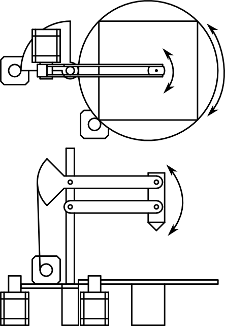
Objects are printed onto a platter that spins back and forth. Its driven via a stepper motor and a large gear. Rollers support the platter around the perimeter and keep it level.
R Axis
Full Size
Four Extruders are each mounted on the end of an arm that swings in and out. The blue protractor things are gears for moving the arms.
Z Axis
Full Size
The Z axis is nothing new. Threaded rods in each corner are synchronized by a timing belt and driven by two stepper motors.
Theres still a lot I've got to do before building it but I'd like some input on the design the way it stands.
Edited 1 time(s). Last edit at 01/21/2013 11:10PM by unlimitedbacon.
I was trying to find a way to build a printer with more than one or two extruders and this is what I came up with. Its not quite the same as the polar printers that have been discussed here before. Its basically a giant 3D printing record player. All the designs are up on Github in Solidworks format.
Features:
+ 4 extruders for multiple colors and materials
+ 320 mm print platter (meets or exceeds the are of current repraps)
+ 80425 mm^2 print area
+ 0.084 degrees/step angular resolution (ϴ Axis)
+ 0.20 mm/step linear resolution (R Axis)

Full Size
ϴ Axis

Full Size
Objects are printed onto a platter that spins back and forth. Its driven via a stepper motor and a large gear. Rollers support the platter around the perimeter and keep it level.
R Axis

Full Size
Four Extruders are each mounted on the end of an arm that swings in and out. The blue protractor things are gears for moving the arms.
Z Axis

Full Size
The Z axis is nothing new. Threaded rods in each corner are synchronized by a timing belt and driven by two stepper motors.
Theres still a lot I've got to do before building it but I'd like some input on the design the way it stands.
Edited 1 time(s). Last edit at 01/21/2013 11:10PM by unlimitedbacon.
|
Re: I designed a polar printer January 22, 2013 05:59AM |
Registered: 11 years ago Posts: 1,807 |
|
Re: I designed a polar printer January 22, 2013 08:11AM |
Registered: 13 years ago Posts: 7,616 |
|
Re: I designed a polar printer January 22, 2013 12:57PM |
Registered: 11 years ago Posts: 374 |
|
Re: I designed a polar printer January 25, 2013 11:07AM |
Admin Registered: 12 years ago Posts: 2,569 |
|
Re: I designed a polar printer January 25, 2013 12:54PM |
Registered: 11 years ago Posts: 374 |
|
Re: I designed a polar printer January 25, 2013 02:02PM |
Registered: 12 years ago Posts: 1,236 |
|
Re: I designed a polar printer January 25, 2013 07:08PM |
Registered: 14 years ago Posts: 43 |
Thanks for the support everyone.
DeuxVis Wrote:
-------------------------------------------------------
> Beautiful design. I am eager to see how you will
> deal with the control electronics and software.
I'd love to hear some suggestions about the electronics. With 4 stepper extruders, it would need to drive 10 motors independently. 1 ϴ Axis + 1 Z Axis + 4 R Axis + 4 E Axis. Right now the only hardware I can find that would support 4 extruders is the old Gen 3 electronics, but it still can't handle enough steppers.
As for the software, I think there is two approaches. You could either write a slicer that generates native G-Code in polar coordinates, or you could have the firmware convert from rectangular to polar coordinates on the fly. In either case, the math is going to get very interesting. Also, the whole thing is complicated by the fact that the system isn't truly polar ( the extruders move on arcs instead of lines ).
bobc Wrote:
-------------------------------------------------------
> I guess that with some ingenuity you could operate
> two extruders simultaneously.
Theoretically, yes. Although you would have to be careful to make sure they don't hit each other.
|
Re: I designed a polar printer January 25, 2013 09:00PM |
Registered: 12 years ago Posts: 1,236 |
unlimitedbacon Wrote:
-------------------------------------------------------
> I'd love to hear some suggestions about the
> electronics. With 4 stepper extruders, it would
> need to drive 10 motors independently. 1 ϴ Axis +
> 1 Z Axis + 4 R Axis + 4 E Axis. Right now the only
> hardware I can find that would support 4 extruders
> is the old Gen 3 electronics, but it still can't
> handle enough steppers.
>
> As for the software, I think there is two
> approaches. You could either write a slicer that
> generates native G-Code in polar coordinates, or
> you could have the firmware convert from
> rectangular to polar coordinates on the fly. In
> either case, the math is going to get very
> interesting. Also, the whole thing is complicated
> by the fact that the system isn't truly polar (
> the extruders move on arcs instead of lines ).
One of the projects I want to do this year is create a controller that supports lots of steppers. I would also like to make it somewhat modular, so for example a base board could handle 4 steppers, an extension board could handle another 8/10 steppers. Running all that will take a fairly big chip.
From what I undestand of delta/polar etc, is that they calculate a theoretical path by solving the appropriate equation, and then move the steppers according to the difference between the current position and the theoretical path.
The Atmega is still the popular chip, but personally I believe the future lies in ARM, which offer far superior price/ performance. e.g. 168Mhz, 512KB Flash, hardware floating point for $10. Of course, software compatibility is an important issue, and unfortunately the ARM chips all have incompatible registers, which means less migration of firmware, so I expect AVR to be around for a while.
Therefore, I would also put the CPU on a module, to allow anything from Atmega to Cortex M4F. This would allow people to run firmware they know and love, and upgrade to faster processor if needed.
|
Re: I designed a polar printer January 25, 2013 09:37PM |
Registered: 11 years ago Posts: 374 |
You should aim to use the new arduino as a base. Paving the way for:
a) Using Ramps with the new Arduino DUE
b) adding on for multiple extruders.
This can pave the way for some bridges we will be crossing soon... Arduino is a great solution as it's readily available, Open, and is modular. This solution also allows use of an ARM processor as you mentioned. I think that kind of power is important for these types of machines with the extra math the firmware does on the fly.
And I think it would be great if the modular add-on extruder boards contained one mosfet with each driver, to make things even more "plug and play".
Edited 2 time(s). Last edit at 01/25/2013 09:42PM by xclusive585.
|
Re: I designed a polar printer January 26, 2013 02:18AM |
Registered: 13 years ago Posts: 7,616 |
Quote
Right now the only hardware I can find that would support 4 extruders is the old Gen 3 electronics, but it still can't handle enough steppers.
Adding steppers is almost trivial as long as you have free pins on your ATmega. Look at the upper half of the Gen7 layout and simply duplicate that onto a dedicated board. You need common 5V, 12V and one ATmega pin for each Step and each Dir. The Enable pin is optional.
Recently I have seen a photo of a Mendel with two Melzi electronics in the wiki. Makes 12 steppers together. Apparently work by Adrian Bowyer, not sure how well it works already.
| Generation 7 Electronics | Teacup Firmware | RepRap DIY |
|
Re: I designed a polar printer January 26, 2013 04:34AM |
Registered: 12 years ago Posts: 1,236 |
Traumflug Wrote:
-------------------------------------------------------
> Recently I have seen a photo of a Mendel with two
> Melzi electronics in the wiki. Makes 12 steppers
> together. Apparently work by Adrian Bowyer, not
> sure how well it works already.
Interesting find, perhaps this page [www.reprap.org]. I count 8 steppers? It appears that RRP are using a serial UART connection with a master/slave setup, possibly they have it wired to do SPI instead. In the github they have some modified Marlin firmware, but it seems preliminary.
Slaving controllers is not a bad way to extend the functions, it lets you reuses existing designs if you can get access to the pins. Slaving with comms would allow a large number of slaves, but does have the disadvantage of multiple firmwares and some comms.
Using comms is perhaps an unnecessary complication, since as Traumflug says you only really need 2 signals per axis (4 per extruder), and even if you max out the GPIOs on a chip, it is easy to add an IO expander, which could drive 16 signals from 2 pins. I guess there is a CPU limit too.
It seems that the distributed approach is how Reprap used to do things, but now monolithic solutions seems to be preferred. It would be a case of slightly reversing the trend.
|
Re: I designed a polar printer January 26, 2013 05:12AM |
Registered: 12 years ago Posts: 1,236 |
xclusive585 Wrote:
-------------------------------------------------------
> You should aim to use the new arduino as a base.
> Paving the way for:
> a) Using Ramps with the new Arduino DUE
> b) adding on for multiple extruders.
>
Yes, I think the Due will greatly help the path to ARM. Atmel SAM would not be my first choice, but I program them for work so I am familiar with them. The SAM3X has plenty of power compared to AVR, it would be great if the Due used the built-in ethernet interface.
I would certainly do a CPU card which is Due compatible, if not the 144 pin chip the 100 pin version for a 2 layer board. Going to 4 layer is 6x the cost where I order my boards.
Unfortunately it now means every ARM based controller uses a different ARM chip, we have LPC1114, LPC1758, LPC1769, SAM3U, SAM3X, and I think there are some STM32 designs out there. The Arduino IDE can be tailored to support any ARM chips, but there will never be official support for chips that are not on Arduino licensed hardware.
I've started a wiki page for "RAMPS-FD", there has been talk in the past so I thought I would get something concrete down.
|
Re: I designed a polar printer January 26, 2013 09:45AM |
Registered: 13 years ago Posts: 7,616 |
Quote
Interesting find, perhaps this page [www.reprap.org]. I count 8 steppers?
Yes, this one. Uhm ... and I always thought Melzi has six stepper drivers, because I've seen RRP's Mendel advertised with triple extruder several months ago. Hah, I was wrong

| Generation 7 Electronics | Teacup Firmware | RepRap DIY |
|
Re: I designed a polar printer February 01, 2013 03:29AM |
Registered: 11 years ago Posts: 4 |
|
Re: I designed a polar printer February 03, 2013 01:02AM |
Registered: 14 years ago Posts: 43 |
So I redesigned it to use a lasercut frame instead of the threaded rods. It may be somewhat less reprapey in this form but theres a couple of advantages.
1. Its cheaper
I figuretively spit my coffee out when I realized how much all that threaded rod was going to cost. There was 15 meters of it. From McMaster, that would have been $60 for the cheap stuff. So assuming I can get access to a laser cutter (btw, does anyone have a laser cutter?) its going to be much cheaper.
2. Its more rigid
Repraps tend to be kind of bendy and I think my original design would have been especially prone to twisting along the Z axis.
3. Its self-aligning
Another problem would have been positioning all the printed components in exactly the right place along the threaded rods. Lasercut parts remove all the guesswork in getting things square or parallel.
Full Size
As usual, everything is up on github.
1. Its cheaper
I figuretively spit my coffee out when I realized how much all that threaded rod was going to cost. There was 15 meters of it. From McMaster, that would have been $60 for the cheap stuff. So assuming I can get access to a laser cutter (btw, does anyone have a laser cutter?) its going to be much cheaper.
2. Its more rigid
Repraps tend to be kind of bendy and I think my original design would have been especially prone to twisting along the Z axis.
3. Its self-aligning
Another problem would have been positioning all the printed components in exactly the right place along the threaded rods. Lasercut parts remove all the guesswork in getting things square or parallel.

Full Size
As usual, everything is up on github.
|
Re: I designed a polar printer February 11, 2013 04:19AM |
Registered: 14 years ago Posts: 43 |
So I've been thinking about the electronics and I think the best thing would be to have multiplexed stepper drivers. Then you could basically hook up as many as you wanted using ribbon cable.
You would not be able to send a step pulse to two drivers simultaniously, but I don't think that really ever happens anyways. In any case, as long as it switches fast enough it shouldn't matter.
You would not be able to send a step pulse to two drivers simultaniously, but I don't think that really ever happens anyways. In any case, as long as it switches fast enough it shouldn't matter.
|
Re: I designed a polar printer February 11, 2013 10:21AM |
Registered: 15 years ago Posts: 376 |
Nice design.
A couple of suggestions
You only need 1 motor to lift the bed. A lead screw has great mechanical advantage so the motor will cope easily. You can remove all the idlers except the ones around the motor pulley. The Makerbot Cupcake had a similar setup without idlers and worked OK. I modified my cupcake and had a sliding motor setup. This removed all the idlers including the ones around the motor.
If you spaced the vertical bearings a little more widely , you could probably get away with only two lead screws on the diagonals as opposed to four.
The 4 extruder setup might be possible with 2 motors. You could use 4 bowden extruders (or more) mounted on an arc as you have them. The Arc could be angled at say 10 degrees. This is similar to the indexing magnifying lenses on a desk microscope.
The first motor indexes to place the chosen extruder to the low point of the arc.
A second motor moves the entire head in and out or along a linear guide.
|
Re: I designed a polar printer February 11, 2013 03:57PM |
Registered: 14 years ago Posts: 43 |
Fascinating, because my Cupcake is exactly the reason I put two motors in. The Z axis starts skipping steps above about 100 mm/min, although that's probably due to bent lead screws and a cheap motor I dug out of a box at a swapmeet. The Prusa Mendel also used two motors. It may be overkill but I think its safe for a proof of concept.
I may have gone overboard with the idlers. I can get rid of most of them if I move the lead screws in farther so the belt doesn't conflict with the smooth rod. Also, do you have a link to the sliding motor cupcake mod?
The microscope lens style thing is a clever idea. Don't professional CNC mills use something similar for changing tools? Wouldn't that be a lot of moving mass?
|
Re: I designed a polar printer April 03, 2013 03:38PM |
Registered: 14 years ago Posts: 43 |
Update:
I have parts! All the vitamins are there. Laser cuttings are laser cutted. Printed parts are being printed. This means I'm committed now. I'm going down the rabbit hole.
As far as the electronics, I'm planning on using a standard RAMPS with an expansion for the extra print heads. It should have enough extra GPIO pins to handle it (barely). ARM is definitely the future, but at this point I think its best not to reinvent any more wheels than I have to.
|
Re: I designed a polar printer April 11, 2013 02:15AM |
Registered: 11 years ago Posts: 29 |
You are brave! The Prism reprap has proven for me, in-the-field, that a belt-driven z-axis is better than one motor for each leadscrew. When designed and built properly it functions better, and breaks better - compared to the two-motor approach. By 'breaks better' what I mean is: if the belt isn't tensioned or something is wrong with the drive system, both leadscrews don't move, or they stutter at the same rate. On two-motor designs it's common to have one motor work, the other motor fail, and then have a misaligned x-axis. This can happen merely by failing to properly maintain the leadscrews such as cleaning and lubrication, so even commercial printers can fail this way.
The challenge for the belt-driven-z is proper alignment. By using the lasercut top/bottom you've kinda licked that problem. I'm not sure if a NEMA17 motor is going to drive that z-axis - or at least it might work but be limited to slow acceleration. You might want to consider a NEMA23 there, especially for 3 extruders or more.
Also would a belt-driven system provide higher resolution for the swing-arms, and perhaps better reliability? I think you might be able to consider this type of revision without needing new laser-cut parts?
One other thing - I think firmware is gong to be really important to success for you. From my experience with CoreXY in Marlin and the Rostock mods to Marlin, you aren't going to get much love for motion based on R + theta. Marlin's planner, which is like Repetier's and Sprinter's motion planners, is truly based on a one-motor-per-axis paradigm. Things like acceleration on the R axis will work fine for you, but printing a line on the platter and having the nozzle accelerate/decelerate during that print move -- that won't work so well (I'm not sure if that will work at all and the required hacks might not work well for the MEGA, not sure...). A friend and I have started looking into generalized solutions for this problem. If any of this makes sense to you, then perhaps you understood the steepness of the hill you are looking to climb. Maybe we could find a way to collaborate and solve this problem for at least three types of machines?
Edited 2 time(s). Last edit at 04/11/2013 02:22AM by tenacious.
|
Re: I designed a polar printer April 11, 2013 08:39PM |
Registered: 11 years ago Posts: 544 |
|
Re: I designed a polar printer May 06, 2013 09:19AM |
Registered: 10 years ago Posts: 979 |
@unlimitedbacon: I have been looking to design something like this with one arm. For acceptance reasons, I would like it to have the same working envelope as a Mendel. The problem is that the practical work envelope is donut shaped. Are you planning on having a no go area in the middle of you plate?
|
Re: I designed a polar printer May 06, 2013 02:56PM |
Registered: 14 years ago Posts: 43 |
|
Re: I designed a polar printer May 06, 2013 05:55PM |
Registered: 10 years ago Posts: 979 |
Assuming you have perfect alignment, you will be able to reach the center. However, you will have limited speed options as you near the center. On a design I am considering, the arm swings up, down, left and right along with a rotating platform. This means that there is a small region in the middle of the platter that is unreachable. (I think I am going to scrap the idea but I am still curious as to how you are going to address the speed issues in the middle.)
Great work!!! I can't wait to see it take life.
Edited 1 time(s). Last edit at 05/06/2013 06:51PM by nicholas.seward.
Great work!!! I can't wait to see it take life.
Edited 1 time(s). Last edit at 05/06/2013 06:51PM by nicholas.seward.
|
Re: I designed a polar printer May 06, 2013 06:44PM |
Registered: 14 years ago Posts: 43 |
The speed issue is an interesting question. I'm glad your brought that up. The center point of the platter is a singularity, in the true mathematical sense of the word. As you approach that point, your speed along the theta axis approaches 0. This is definitely a disadvantage of this design, as small parts will take longer to print than they would on a conventional printer. The simplest solution would be to print smaller parts somewhere off center.
My idea was to allow the arms to overshoot the center. That is to say, you can allow coordinates with a limited negative r value. Lets say you are making a move that passes directly over the singularity. If the arm cannot swing past the center, then it will stop when it reaches that point, the platter will spin 180°, and then the arm will keep going. If you allow the arm to move past center, then it can sweep right across without stopping.
Fortunately, this effect is a double edged sword. Although your speed decreases as you approach the center, your resolution increases. If I wanted, i could advertise my printer as havity ∞ resolution, and this would be technically correct (the best kind of correct). Unfortunately its also rather misleading, as its only true for r=0. In any case, I designed my printer to match the resolution of a mendel near the perimeter, so it will always be able to beat a current reprap in terms of resolution (on the theta axis, anyways).
I'm still not sure why you would have an unreachable area in the center. If thats really the case, I guess you could just use a really huge platter so the thickness of your donut is equal to the width of a Mendel. That would get you the area you want. Could you draw a diagram? I'm interesting in seeing your design.
Edited 3 time(s). Last edit at 05/07/2013 08:06PM by unlimitedbacon.
|
Re: I designed a polar printer May 06, 2013 07:42PM |
Registered: 14 years ago Posts: 43 |
tenacious Wrote:
-------------------------------------------------------
> Also would a belt-driven system provide higher
> resolution for the swing-arms, and perhaps better
> reliability? I think you might be able to
> consider this type of revision without needing new
> laser-cut parts?
I'm trying to figure out how that would work. Definitely something to look in to.
> One other thing - I think firmware is gong to be
> really important to success for you. From my
> experience with CoreXY in Marlin and the Rostock
> mods to Marlin, you aren't going to get much love
> for motion based on R + theta. Marlin's planner,
> which is like Repetier's and Sprinter's motion
> planners, is truly based on a one-motor-per-axis
> paradigm. Things like acceleration on the R axis
> will work fine for you, but printing a line on the
> platter and having the nozzle
> accelerate/decelerate during that print move --
> that won't work so well (I'm not sure if that will
> work at all and the required hacks might not work
> well for the MEGA, not sure...). A friend and I
> have started looking into generalized solutions
> for this problem. If any of this makes sense to
> you, then perhaps you understood the steepness of
> the hill you are looking to climb. Maybe we could
> find a way to collaborate and solve this problem
> for at least three types of machines?
Software is going to make or break this machine. I am not an experienced coder by any means, but I know enough to know the huge mess I'm getting into and I'm definitely going to need all the help I can get.
aduy Wrote:
-------------------------------------------------------
> this is cool, i like how the extruders swing in,
> and the firmware shouldnt be too hard to mod,
> afterall look at how the delta bot works. have you
> worked out what the equation is in cartesion is
> yet, time to do some maths.
This whole thing is complicated by the fact that this machine is not truly polar. The r axis moves on an arc. The conversion from cartesian coordinates to this pseudo polar form is given by:
Where h is the radius of the platter and arm (they are equal on my machine). Note that even though I use r, it is actually an angle in either degrees or radians. And oh yah, and thats one of those screwy tangents where you have to take into account which quadrant your in.
Now the real trick is how you get from that to the timing required to drive stepper motors.
-------------------------------------------------------
> Also would a belt-driven system provide higher
> resolution for the swing-arms, and perhaps better
> reliability? I think you might be able to
> consider this type of revision without needing new
> laser-cut parts?
I'm trying to figure out how that would work. Definitely something to look in to.
> One other thing - I think firmware is gong to be
> really important to success for you. From my
> experience with CoreXY in Marlin and the Rostock
> mods to Marlin, you aren't going to get much love
> for motion based on R + theta. Marlin's planner,
> which is like Repetier's and Sprinter's motion
> planners, is truly based on a one-motor-per-axis
> paradigm. Things like acceleration on the R axis
> will work fine for you, but printing a line on the
> platter and having the nozzle
> accelerate/decelerate during that print move --
> that won't work so well (I'm not sure if that will
> work at all and the required hacks might not work
> well for the MEGA, not sure...). A friend and I
> have started looking into generalized solutions
> for this problem. If any of this makes sense to
> you, then perhaps you understood the steepness of
> the hill you are looking to climb. Maybe we could
> find a way to collaborate and solve this problem
> for at least three types of machines?
Software is going to make or break this machine. I am not an experienced coder by any means, but I know enough to know the huge mess I'm getting into and I'm definitely going to need all the help I can get.
aduy Wrote:
-------------------------------------------------------
> this is cool, i like how the extruders swing in,
> and the firmware shouldnt be too hard to mod,
> afterall look at how the delta bot works. have you
> worked out what the equation is in cartesion is
> yet, time to do some maths.
This whole thing is complicated by the fact that this machine is not truly polar. The r axis moves on an arc. The conversion from cartesian coordinates to this pseudo polar form is given by:


Where h is the radius of the platter and arm (they are equal on my machine). Note that even though I use r, it is actually an angle in either degrees or radians. And oh yah, and thats one of those screwy tangents where you have to take into account which quadrant your in.
Now the real trick is how you get from that to the timing required to drive stepper motors.
|
Re: I designed a polar printer May 07, 2013 10:10AM |
Registered: 10 years ago Posts: 979 |
Here is the picture of my design that has up to a one inch diameter dead zone in the middle of the platter. I love the simplicity. I don't love the hole. (This is a functionality drawing. It is not meant to reflect how I would actually build it.) I am scrapping this idea. I am still in my brainstorming phase.
Edited 1 time(s). Last edit at 05/07/2013 10:11AM by nicholas.seward.

Edited 1 time(s). Last edit at 05/07/2013 10:11AM by nicholas.seward.
|
Re: I designed a polar printer July 11, 2013 05:12AM |
Registered: 14 years ago Posts: 43 |
Progress!
Assembly is nearing completion. Next comes basic movement testing. For electronics we are planning to use Decapede [www.reprap.org] which is still in development. Stay tuned.

Assembly is nearing completion. Next comes basic movement testing. For electronics we are planning to use Decapede [www.reprap.org] which is still in development. Stay tuned.
|
Re: I designed a polar printer July 11, 2013 04:34PM |
Registered: 10 years ago Posts: 979 |

Sorry, only registered users may post in this forum.