Tri-Polar Bot Concept -- Meet Wally
Posted by see3d
|
Re: Tri-Polar Bot Concept -- Meet Wally July 20, 2013 04:01PM |
Registered: 11 years ago Posts: 58 |
Perhaps your testing has already proven out the Hall effect sensors, but I was concerned that there might be some considerable uncertainty finding the maximum, as well as some additional firmware complexity, and was looking for a way to make it more certain. I've actually tossed around a few ideas since then, until I realized that the 180 degree position is actually a limit; the arm really shouldn't go past that point, as far as I can tell. That means a mechanical endstop could be used.
I think the best one that I've come up with is shown in the attached file. It uses an ordinary microswitch buried in the top edge of the lower arm, a small protrusion underneath the pulley to activate it and a relocated pulley to minimize the size of the protrusion. Actually I think the thing you'd want under the pulley is a small block with an embedded nut, so there can be microadjustment of the actuation point with a screw. Does that make sense?
I realize that locating the pulley low might be an issue, based on how the motor brackets are set up, though from some perspectives it actually looks like it would be easier to have it in that position.
It would also be possible to mount an opto endstop on the outside of the lower arm, with the flag attached to the bottom of the pulley; in that case, the adjustment might be harder though.
Does any of that look like it might be applicable to the problem?
|
Re: Tri-Polar Bot Concept -- Meet Wally July 21, 2013 03:01PM |
Registered: 10 years ago Posts: 979 |
I am revisiting physical end stops. However, changing one angle changes the other so having contactless limit switches is preferred.
I am playing with some rearranging of the arms. I can eliminate the double lamina joint and save some complexity. (For now, the DLCJ will be needed for the tool changer version but I can't bring myself to put a unnecessary point of failure that adds 2 bearings, 2 plastic pieces, and assembly time.) I also have need to move the center of gravity down. Currently, I am afraid of Wally vibrating off the table.
The pulley placement seems to be a reoccurring concern of others so I will reevaluate that.
I hope to have some ideas posted soon. My goal is to have some version of Wally moving by Friday.
|
Re: Tri-Polar Bot Concept -- Meet Wally July 21, 2013 03:51PM |
Registered: 10 years ago Posts: 100 |
I like the idea of making the first version of Wally (full production, not necessarily the betas), the simplest possible configuration that can meet the lowest BOM cost, but at least make high quality PLA prints.
Once the baseline design is performing reliably in the field, the risk of designing in more functionality is greatly reduced.
Switching tools is a really sophisticated feature that will require a lot of extra engineering and testing to get right.
It is good to go through the design exercises right from the beginning to consider the more advanced possibilities, but the first implementation, if consisting of only the vital elements, will initially cut down the number of possible failure points.
|
Re: Tri-Polar Bot Concept -- Meet Wally July 23, 2013 11:33AM |
Registered: 10 years ago Posts: 7 |
Nicholas,
How do you intend to eliminate the DLCJ? Will you keep the same 2 point joint at the end or will you go to a single point solution and single printer head much like the Morgan Scara 3d Printer? I have been trying to design a similar arm configuration with no luck of keeping the hot end in the proper orientation at all times.
It seemed that your DLCJ wuold have been the best solution to that, if you don't mind the risk and added components. I keep feeling though there has to be some simple solution.
|
Re: Tri-Polar Bot Concept -- Meet Wally July 23, 2013 11:56AM |
Registered: 10 years ago Posts: 979 |
Using 6805 bearings with a concentrically mounted hot end is too expensive. Each bearing costs around $4 and I would need 2. (I can buy 32 608 bearing at $0.25 a piece.) I am going with an arm mounted hot end. It is breaking my symmetry but it will save me 2 608 bearings over the DLCJ. I love the DLCJ solution but I can't leave any possible cost saving on the table that would also make the design more robust.
Sneak peak
Edited 3 time(s). Last edit at 07/24/2013 12:56AM by nicholas.seward.

Sneak peak
Edited 3 time(s). Last edit at 07/24/2013 12:56AM by nicholas.seward.
|
Re: Tri-Polar Bot Concept -- Meet Wally July 23, 2013 01:15PM |
Registered: 10 years ago Posts: 979 |
I just found some 6805 bearings (25x37x7) for <$1 a piece. I think I will revisit the concentric mounting. I think most people would be receptive to spending an extra $1.50 to get a cleaner looking robot.
I am also looking at 6801 bearings (12x21x5) for $0.70.
Edited 1 time(s). Last edit at 07/23/2013 01:43PM by nicholas.seward.
I am also looking at 6801 bearings (12x21x5) for $0.70.
Edited 1 time(s). Last edit at 07/23/2013 01:43PM by nicholas.seward.
|
Re: Tri-Polar Bot Concept -- Meet Wally July 23, 2013 02:24PM |
Registered: 10 years ago Posts: 7 |
Yeah I knew they were out there for cheaper. And I agree, people are willing to pay more for the cleaner look, not to mention that maximizes the potential of the arms (you don't need a 9 inch arm to reach an 8 inch distance).
It will also be an easier inverse kinematic equation for calculations and that in itself is definitely worth the extra $1.
It will also be an easier inverse kinematic equation for calculations and that in itself is definitely worth the extra $1.
|
Re: Tri-Polar Bot Concept -- Meet Wally July 25, 2013 08:31PM |
Registered: 10 years ago Posts: 979 |
If it matters to anyone, I ended up with 6702 bearings for the concentric hot end.
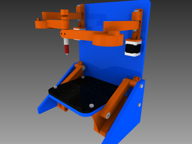
I am having fits trying to figure out how to lift and lower the bed. I have a ton of ideas and some of them are even workable. However, I am not in love with any of them so I am going to just post the picture of how Wally currently looks and see if you guys can come up with an elegant solution that I haven't even thought of. Keep in mind that the bed will be somewhat heavy. There will be a 350W power supply mounted below it. The 3/8" volcanic glass bed will also be heavy. I am thinking I need to at least get a mechanical advantage of 2 in addition to having a smallish drive pulley/spool.
Additional note: All mounts are now one-sided making tolerances matter less and making it easier to assemble.
Edited 1 time(s). Last edit at 07/25/2013 08:32PM by nicholas.seward.
|
Re: Tri-Polar Bot Concept -- Meet Wally July 25, 2013 10:22PM |
Registered: 10 years ago Posts: 100 |
One possibility is to have a vertical slit in the back board that a shaft attached to the bed edge goes through. Then the bed raising string can be attached to the back side of the board. The stepper can be mounted directly to the board with its backside facing straight out from the board. Put a bearing/pulley on the shaft and it can have a 2:1 mechanical advantage. Make the pulley like a V groove. The string will be outside of the heated zone. If you don't mind putting another idler on the back, the motor could be mounted way off to the side and top or bottom and the string could still be attached to the inside middle of the bed. A geared stepper like used in extruders is also a possibility for more power and mechanical advantage. Backlash would not be an issue.
When you say the PS is mounted below the bed, do you mean attached directly to the underside of the bed, or below the lowest position of the bed, but on the back board?
When you say the PS is mounted below the bed, do you mean attached directly to the underside of the bed, or below the lowest position of the bed, but on the back board?
|
Re: Tri-Polar Bot Concept -- Meet Wally July 25, 2013 10:27PM |
Registered: 10 years ago Posts: 979 |
|
Re: Tri-Polar Bot Concept -- Meet Wally July 26, 2013 01:24AM |
Registered: 11 years ago Posts: 89 |
|
Re: Tri-Polar Bot Concept -- Meet Wally July 26, 2013 01:59AM |
Registered: 10 years ago Posts: 979 |

I tried putting the power suppy on the backboard and just couldn't find a workable solution. Here is my current plan. I will shield the controller so nobody accidentally pokes it. I will put the PS connections toward the backboard. This should keep the wiring pretty clean and out of the way.

I also added a pulley onto the bed that protrudes through a slit in the backboard. I will be able to lift the heavyish bed now. I will be able to lift a 30-40lb bed. I think I am safe. The other stepper in the picture will be the filament drive. I have not drawn the mount yet because I haven't gotten the modified MBE filament drives from QU-BD that I will be using. (I should be able to pick up some tomorrow.) When I do, I will make a single piece that mounts both. I am all about part count reduction.
Edited 2 time(s). Last edit at 07/26/2013 02:01AM by nicholas.seward.
|
Re: Tri-Polar Bot Concept -- Meet Wally July 27, 2013 11:00PM |
Registered: 11 years ago Posts: 1,049 |
How about a sliding table with rod to keep it straight.
Putting PS on table --- bad idea
Lifting un-necessary weight
put PS in base

Putting PS on table --- bad idea
Lifting un-necessary weight
put PS in base
|
Re: Tri-Polar Bot Concept -- Meet Wally July 27, 2013 11:50PM |
Registered: 10 years ago Posts: 979 |
We decided early on that the sliding table idea was more complex than a traditional sliding z so we decided to either go with a Morgan style z or do the 4 bar that you see here.
We are moving the PS and the controller to a new board that will be on the bottom of the robot. I think the PS under the table will be fine but the added board will give increased stability and will give me to place little rubber feet. All good designs need little rubber feet. I will post some pictures soon to get some feedback.
We are moving the PS and the controller to a new board that will be on the bottom of the robot. I think the PS under the table will be fine but the added board will give increased stability and will give me to place little rubber feet. All good designs need little rubber feet. I will post some pictures soon to get some feedback.
|
Re: Tri-Polar Bot Concept -- Meet Wally July 28, 2013 12:02AM |
Registered: 10 years ago Posts: 100 |
The other thing that a bottom board will provide is an easy way to clamp Wally close to the edge of a table without fear that it could get knocked off by an accidental bump or a resonant walking motion. It could be a spring clamp, bar clamp, or "C" clamp. Not a bad idea if it is being shown at a meet. I don't think Wally would like being dropped on his head. 
|
Re: Tri-Polar Bot Concept -- Meet Wally July 28, 2013 04:39AM |
Registered: 10 years ago Posts: 979 |
Dennis,
Here is my birthday present to you! I have to admit that I am glad you pushed so hard on getting the electronics stationary. This looks like a better product.
I am working on wire management. Hopefully, I will have something to post on that soon.
Edited 1 time(s). Last edit at 07/28/2013 04:40AM by nicholas.seward.
Here is my birthday present to you! I have to admit that I am glad you pushed so hard on getting the electronics stationary. This looks like a better product.

I am working on wire management. Hopefully, I will have something to post on that soon.
Edited 1 time(s). Last edit at 07/28/2013 04:40AM by nicholas.seward.
|
Re: Tri-Polar Bot Concept -- Meet Wally July 28, 2013 05:18AM |
Registered: 10 years ago Posts: 979 |

What do you think about this method for wire management? The steppers and their mount (not pictured) will hold all the wires in place. Slight tension should keep the rest in the grooves. If that isn't enough I could put some zip tie holes.
Edited 1 time(s). Last edit at 07/28/2013 05:19AM by nicholas.seward.
|
Re: Tri-Polar Bot Concept -- Meet Wally July 28, 2013 01:01PM |
Registered: 11 years ago Posts: 1,049 |
|
Re: Tri-Polar Bot Concept -- Meet Wally July 28, 2013 01:03PM |
Registered: 10 years ago Posts: 979 |
|
Re: Tri-Polar Bot Concept -- Meet Wally July 28, 2013 02:06PM |
Registered: 10 years ago Posts: 100 |
|
Re: Tri-Polar Bot Concept -- Meet Wally July 28, 2013 02:08PM |
Registered: 10 years ago Posts: 979 |
|
Re: Tri-Polar Bot Concept -- Meet Wally July 28, 2013 02:20PM |
Registered: 10 years ago Posts: 18 |
|
Re: Tri-Polar Bot Concept -- Meet Wally July 28, 2013 02:28PM |
Registered: 10 years ago Posts: 979 |
No, wall mounting is out with the new z-lift. You could put a few 42.5mm standoffs and still mount it to a wall. However, it would be hard to get to the filament drive.
Of course, you can do all sorts of mods to make this fit your need. You could easily mount the Z and the E motor on the front way above everything. I was just trying to keep the CG low and the overall height minimized.
My intention was never to mount Wally on a wall. It is named Wally more for the fact that everything is referenced off 1 board. However, it would be awesome to see large versions permanently mounted to a wall.
|
Re: Tri-Polar Bot Concept -- Meet Wally July 28, 2013 06:42PM |
Registered: 11 years ago Posts: 58 |
|
Re: Tri-Polar Bot Concept -- Meet Wally July 28, 2013 07:50PM |
Registered: 10 years ago Posts: 979 |
With a mechanical advantage of 7 I need 1/32 driver to get at least 25 micron resolution everywhere. It follows that 1/16 drivers would have at least 50 micron resolution. That said you can look at the resolution map I posted early to see that 1/16 drivers will get you better than 25 micron resolution most places in the area.
The real reason I use 1/32 is that is what QU-BD sells. They also have the added benifits of reducing stepper noise.
The real reason I use 1/32 is that is what QU-BD sells. They also have the added benifits of reducing stepper noise.
|
Re: Tri-Polar Bot Concept -- Meet Wally July 28, 2013 08:22PM |
Registered: 10 years ago Posts: 100 |
I mocked up the Wally box out of cardboard today. I wanted to get a feel for the physical size of Wally as proposed. I blackened in the spots where the 4 stepper motors would go and looked for a cut in wire channel path that I thought would look good and be efficient. I ended up with a path that is shaped like a "V" on the back.
I also wanted to get a feel for how much of the back board was left unsupported at the top relative to the active arm components. The side view shows where I feel the best structural height would be vs the drawn in lines for the latest proposed height. It is just gut feel at this point. I don't know that lower would not be good enough.
I also wanted to get a feel for how much of the back board was left unsupported at the top relative to the active arm components. The side view shows where I feel the best structural height would be vs the drawn in lines for the latest proposed height. It is just gut feel at this point. I don't know that lower would not be good enough.

|
Re: Tri-Polar Bot Concept -- Meet Wally July 28, 2013 08:59PM |
Registered: 11 years ago Posts: 1,049 |
|
Re: Tri-Polar Bot Concept -- Meet Wally July 28, 2013 09:06PM |
Registered: 10 years ago Posts: 979 |
|
Re: Tri-Polar Bot Concept -- Meet Wally July 29, 2013 01:19AM |
Registered: 10 years ago Posts: 18 |
I was first worried that the V slot would weaken the structue at the top of V area, but now realize it is only a trench rather than slot, so looks like it won't go right thro the board. I like the way it is coming together.
If wall mponting is not needed, will it be possible to mount the fillament reel on the back with some sort of spool holder stradling the vertical slot?
If wall mponting is not needed, will it be possible to mount the fillament reel on the back with some sort of spool holder stradling the vertical slot?
|
Re: Tri-Polar Bot Concept -- Meet Wally July 29, 2013 01:23AM |
Registered: 10 years ago Posts: 979 |


Sorry, only registered users may post in this forum.