Tri-Polar Bot Concept -- Meet Wally
Posted by see3d
|
Tri-Polar Bot Concept -- Meet Wally June 23, 2013 10:18PM |
Registered: 10 years ago Posts: 100 |
Hello,
First post here. There has been a thread going on for a short while on the "Delta robot 3D printers" Google Group titled "Delta mechanism variant" by Billy Zelsnack. Billy started it to explore using different simple arm mechanisms to position X,Y with a fixed Z plane. A lot of ideas were brainstormed by several contributors over the last couple of weeks. One complete concept grew out of those sessions for a Tri-Polar Bot. X,Y, and Z axis are all along radial coordinates, rather than straight. This concept does not fit the Delta definition, so one contributor (Nicholas Seward of Simpson fame), suggested that the discussions should be moved to this forum. So, here I am (Dennis Brown aka see3d) to introduce Wally (yes, it is named for a geneticist, but on a first name basis). Wally is a wall bot. Everything is referenced of a back board. Nicholas also thought that Wally would lend itself well to a RepRap design. I put together a paper model of the arms to see how they would work, and then did some schematic drawings of a side view, and a view looking up from Yoda's point of view. They are attached here:
Wally evolved out of some prior design ideas. The arms look like a simplified early Simpson prototype. The fishing line drive came from other recent Delta and Cartesian bots. The wall bot idea came from some recent Delta design brainstorming. The crazy math to translate coordinate systems was shown to work for Delta bots. I have not identified any bot crazy enough to use a 4 bar linkage for the Z yet, but that can't be new. There was a lot of cross pollination to conceive Wally.
The idea was to make Wally as simple and low cost as possible while maintaing a decent build volume and precision. Simple and build volume can be seen from the concept. Low cost is assumed due to only rotating bearings and no fancy linear actuators or precision lead screws. It will take a detailed design, a working prototype with BOM, and real 3D prints to verify the cost and precision are there.
Details about the concept:
> Built off a rigid back board. The board can have ribs attached to make it more rigid. The material is TBD based on prototype needs.
> Wally could be designed to fold fairly flat for storage or portability. Think suitcase with a handle on the side. Legs could fold out to make it free standing, or it could be attached to a wall.
> The design can be scaled. Perhaps a 12" backboard width at the small end. That might give more than a 6" cube build volume. A 15" backboard width might give something on the order of 10" Diameter, or an 8" square, or a 10" x 7" Rectangle -- all with a 10" height. I think this would be a good design center.
> All axis are driven from stepper motors through a Spectra fishing line drive on preferably smooth pulleys.
> The two X,Y arms are driven by rotating the elbows. This gives a build area that is limited by an arc from the shoulder with a straight elbow to the hot end.
> The ratio of the stepper drive to large elbow pulley determines the resolution and torque. 0.025mm or better with a reasonable ratio with a 16-32x microstep.
> The Z axis is a 4 bar linkage that keeps the bed flat as it is rotated up and down through an arc. Gravity lowers and a stepper winding a string raises it.
> The build platform moves through an arc as the Z is changed. The X,Y Arms have to compensate for the displacement in the Y axis (perpendicular to the back board).
> A convenient place for a spool is on the lower back. Filament would be fed up through a Bowden extruder and over the top and down to the hot end.
If I missed some important point, please ask about it. I am doing this summary from memory of 5 pages of posts in Billy's thread.
Other brainstorming ideas:
An end stop for both arms and possibly a table leveling Z probe might be able to be designed with just one microswitch located on the effector.
It might be possible to have a hot end tool changer. If the hot end is held with magnets on the effector, the hot end could be parked along the back wall to be picked up as needed. A strong hold magnet at the backboard could be magnetically adjusted to hold or release a tool. They would each have to have their own Bowden extruder. This would allow for multiple extrusion heads that stayed in the same center of arm rotation, and did not require any reduction in build area.
With a universal holder design, things like a Laser Diode head, a light duty rotary cutter head, a magic marker, or a clay extruder could be accommodated. To offset some of the weight of a heavy tool, a counterbalancing string could be added from above. How practical these things would be would have to be tested in a prototype.
Next steps:
The next thing needed is to have real MCAD design work done to verify all the X,Y, and Z movements and build volumes. That is not my realm.
Then some design work on the arms to make them into 3D printable form.
Then building a prototype arm assembly to test the ideas in real life.
Then likely change the design to make it work better.
Then do the same for the Z axis.
Finally put all the pieces together and put the juice to Wally to make him alive!
My contribution to Wally was to pull the various pieces together into a complete printer concept.
I would like to build Wally at some point, but need an experienced 3D bot maker to lead the way (or a group of collaborators).
I am currently waiting for delivery of my first 3D printer kit from the RigidBot KickStarter.
First post here. There has been a thread going on for a short while on the "Delta robot 3D printers" Google Group titled "Delta mechanism variant" by Billy Zelsnack. Billy started it to explore using different simple arm mechanisms to position X,Y with a fixed Z plane. A lot of ideas were brainstormed by several contributors over the last couple of weeks. One complete concept grew out of those sessions for a Tri-Polar Bot. X,Y, and Z axis are all along radial coordinates, rather than straight. This concept does not fit the Delta definition, so one contributor (Nicholas Seward of Simpson fame), suggested that the discussions should be moved to this forum. So, here I am (Dennis Brown aka see3d) to introduce Wally (yes, it is named for a geneticist, but on a first name basis). Wally is a wall bot. Everything is referenced of a back board. Nicholas also thought that Wally would lend itself well to a RepRap design. I put together a paper model of the arms to see how they would work, and then did some schematic drawings of a side view, and a view looking up from Yoda's point of view. They are attached here:


Wally evolved out of some prior design ideas. The arms look like a simplified early Simpson prototype. The fishing line drive came from other recent Delta and Cartesian bots. The wall bot idea came from some recent Delta design brainstorming. The crazy math to translate coordinate systems was shown to work for Delta bots. I have not identified any bot crazy enough to use a 4 bar linkage for the Z yet, but that can't be new. There was a lot of cross pollination to conceive Wally.
The idea was to make Wally as simple and low cost as possible while maintaing a decent build volume and precision. Simple and build volume can be seen from the concept. Low cost is assumed due to only rotating bearings and no fancy linear actuators or precision lead screws. It will take a detailed design, a working prototype with BOM, and real 3D prints to verify the cost and precision are there.
Details about the concept:
> Built off a rigid back board. The board can have ribs attached to make it more rigid. The material is TBD based on prototype needs.
> Wally could be designed to fold fairly flat for storage or portability. Think suitcase with a handle on the side. Legs could fold out to make it free standing, or it could be attached to a wall.
> The design can be scaled. Perhaps a 12" backboard width at the small end. That might give more than a 6" cube build volume. A 15" backboard width might give something on the order of 10" Diameter, or an 8" square, or a 10" x 7" Rectangle -- all with a 10" height. I think this would be a good design center.
> All axis are driven from stepper motors through a Spectra fishing line drive on preferably smooth pulleys.
> The two X,Y arms are driven by rotating the elbows. This gives a build area that is limited by an arc from the shoulder with a straight elbow to the hot end.
> The ratio of the stepper drive to large elbow pulley determines the resolution and torque. 0.025mm or better with a reasonable ratio with a 16-32x microstep.
> The Z axis is a 4 bar linkage that keeps the bed flat as it is rotated up and down through an arc. Gravity lowers and a stepper winding a string raises it.
> The build platform moves through an arc as the Z is changed. The X,Y Arms have to compensate for the displacement in the Y axis (perpendicular to the back board).
> A convenient place for a spool is on the lower back. Filament would be fed up through a Bowden extruder and over the top and down to the hot end.
If I missed some important point, please ask about it. I am doing this summary from memory of 5 pages of posts in Billy's thread.
Other brainstorming ideas:
An end stop for both arms and possibly a table leveling Z probe might be able to be designed with just one microswitch located on the effector.
It might be possible to have a hot end tool changer. If the hot end is held with magnets on the effector, the hot end could be parked along the back wall to be picked up as needed. A strong hold magnet at the backboard could be magnetically adjusted to hold or release a tool. They would each have to have their own Bowden extruder. This would allow for multiple extrusion heads that stayed in the same center of arm rotation, and did not require any reduction in build area.
With a universal holder design, things like a Laser Diode head, a light duty rotary cutter head, a magic marker, or a clay extruder could be accommodated. To offset some of the weight of a heavy tool, a counterbalancing string could be added from above. How practical these things would be would have to be tested in a prototype.
Next steps:
The next thing needed is to have real MCAD design work done to verify all the X,Y, and Z movements and build volumes. That is not my realm.
Then some design work on the arms to make them into 3D printable form.
Then building a prototype arm assembly to test the ideas in real life.
Then likely change the design to make it work better.
Then do the same for the Z axis.
Finally put all the pieces together and put the juice to Wally to make him alive!
My contribution to Wally was to pull the various pieces together into a complete printer concept.
I would like to build Wally at some point, but need an experienced 3D bot maker to lead the way (or a group of collaborators).
I am currently waiting for delivery of my first 3D printer kit from the RigidBot KickStarter.
|
Re: Tri-Polar Bot Concept -- Meet Wally June 24, 2013 07:08AM |
Registered: 10 years ago Posts: 979 |
Welcome to the RepRap forum. I am working on MCAD for Wally and had hoped to post an animation by now but it is looking like you will have to wait another day or two. (I can't let myself just post a proof of concept mockup. I have to design it down to the bolt.) I dig into a design. I hit a snag. I sit around for a while. I have an epiphany. I dig into a redesign. I hit a snag. I sit around for a while. etc.
I am trying to mount swing out legs, z-arms, and xy-arms all to the save vertical shaft. Everything is getting a little crowded. I am also trying to have symmetry. Something is going to have to give.
Edited 1 time(s). Last edit at 06/24/2013 08:54AM by nicholas.seward.
I am trying to mount swing out legs, z-arms, and xy-arms all to the save vertical shaft. Everything is getting a little crowded. I am also trying to have symmetry. Something is going to have to give.
Edited 1 time(s). Last edit at 06/24/2013 08:54AM by nicholas.seward.
|
Re: Tri-Polar Bot Concept -- Meet Wally June 24, 2013 03:08PM |
Registered: 10 years ago Posts: 100 |
|
Re: Tri-Polar Bot Concept -- Meet Wally June 26, 2013 12:52AM |
Registered: 10 years ago Posts: 979 |
Video: http://www.youtube.com/watch?v=RLMNi368M6U
Using an idea similar to a scissor lift, I made a mockup of the xy-stage. Mockup may be the wrong word. It is ready to be printed. I had to shrink the arms and the bed to 150mm to make it easy to print with my 150x150mm machine. Scaling is pretty straight forward.
I was worried about backlash in the gears but I addressed it with a mounting insert with an eccentric hole. You can see it on the bottom of the tool carriage in the video.
The bed in the video is actually 150x175 to prove to myself it can do 150x150 no matter what offset from the z arc.
I am more excited about this than I am about Simpson. I am looking forward to printing this guy out.
Oh, I didn't size the pulleys. I put a 100mm pulley on the elbow just for show. I will need to pick the size of both pulleys to get the desired speed, resolution, and acceleration. Any suggestions on these values.
Edited 2 time(s). Last edit at 06/26/2013 12:54AM by nicholas.seward.
|
Re: Tri-Polar Bot Concept -- Meet Wally June 26, 2013 03:19AM |
Registered: 11 years ago Posts: 72 |
|
Re: Tri-Polar Bot Concept -- Meet Wally June 26, 2013 08:49AM |
Registered: 10 years ago Posts: 979 |
I did't model it but the plastic that connects the two arms can have any number of extruders or have an automatic tool changer. The prototype (If I build it.) will start with a solid carriage but it would be an easy mod to have an array of tools between the steppers and have Wally pick one up with passive magnets. He could let go by putting the tool in a slot and then moving sideways.
I am thinking of at least 3 tools right now. PLA/ABS; PVA (water soluble support material); z probe (for leveling)
See3D mentioned other possible tools: Laser Diode head, rotary cutter head, a magic marker, paste extruder. I would add paper cutter to the list.
By my math we can easy fit 3 tools and we can probably squeeze in 4 tools. That is with 25mm wide tools with with at least 25mm of dead space between the tools.
BTW, I did a quick calculation and this is probably the cheapest XY stage known to man. I came up with about $30 including the steppers and excluding any effectors.
|
Re: Tri-Polar Bot Concept -- Meet Wally June 26, 2013 10:34AM |
Nicholas,
That's a very innovative design. However, the kinematic model of your mechanism is probably quite complex. Besides, I don't think the orientation of the end-effector (the triangular body) remains constant. Finally, you may change the gears with a double-lamina compliant joint (see Section 1.1 of this thesis: [wwwrobot.gmc.ulaval.ca]).
Ilian
www.twitter.com/ibonev
|
Re: Tri-Polar Bot Concept -- Meet Wally June 26, 2013 10:47AM |
Registered: 10 years ago Posts: 979 |
Agreed. The kinematics are quite complex. (Does that really matter with computers now days?) The end-effector just splits the angle between the forearms so no it doesn't maintain a constant orientation. However, a constant orientation isn't need. I was trying this setup to be able to have symmetry and have a near constant orientation.
I love the double-lamina compliant joint. I will experiment with two cylinders with braided fishing line in a figure-8 pattern between the two. Something similar to this.
I love the double-lamina compliant joint. I will experiment with two cylinders with braided fishing line in a figure-8 pattern between the two. Something similar to this.
|
Re: Tri-Polar Bot Concept -- Meet Wally June 26, 2013 03:03PM |
Registered: 10 years ago Posts: 100 |
That 3D design and animation is just so cool, Nicholas!!!
If you can get a 150mm square+Z shift, you should be able to get about a 175mm diameter + Z shift.
Since you are so far along with the basics, let's jump into some fine details (some previously mentioned elsewhere, but repeated here just for the design record).
I like the simplicity of the gears, but due to my lack of experience and wondering about how much precision is in printed gears, I would personally feel more comfortable with a circle and string configuration. Your figure "8" string idea would be one cool way to do it. How much does the angle change between the backboard and the effector over the range of motion? If it is too much, you can use another method to reference the effector angle off the backboard using 3 circular pulleys on one arm as shown here:
I am not certain, but perhaps it only takes one piece of string attached at the back board and wound around all the pulleys and back to the backboard again with a bit of spring tension. I would see the pulleys as fixed (no bearings) printed to the bottom of the motor mount and the effector, and one idler pulley with bearing at the underside of the elbow joint.
I had wondered about the precision of printed pulleys due to the string being caught into the layering grooves. I considered a post print operation of rotating a pulley on its own bearings while using something like a router, disk sander, mill, or whatever cutter to take a skim pass to clean up the diameter. Sort of the inverse of reaming out a 3d printed hole to the perfect size. There could even be a 3D printed fixture made just for this process. Who says you can't 3D print an assembly or post-op fixture as part of the printer design! It could have a screw to adjust the shaved diameter to the exact dimension (need calipers to measure it). Clamp it to a drillpress that has an end mill chucked up as one possibility. It would also be possible to wrap the large pulley with a strip of tape, like the HVAC aluminum tape to smooth the printed grooves or minimize the wear.
As far a tensioning the main arm strings, I think a small stiff spring on the big pulley would work. The complete diameter of the pulley is not used, so there is an area to attach the string to the pulley at one point, around the motor pulley a few turns and back to the big pulley. Here is a diagram:
Notice that I can also do a figure "8" on this to give a little more contact area and keep the string a little more compact. The string on the motor pulley would walk up and down as it wrapped and unwrapped the string. The big pulley only makes a half turn, so the string would not technically walk. It would wrap in a wide spiral as the motor pulley string walked, depending on the pulley ratio. The string does not need to wrap all the way around the big pulley, but I thought it might be a little better for the stress points and to reduce the needed spring tension for it to take a couple of wraps anyway. There could also be other winding arrangements, like take the takeoff of the big pulley to the motor pulley from the second wrap inside. That might make the placement of the connections to the ends of the strings less stressful and not as constrained as to the allowable pie zone for placement. I like that idea, so I just changed the picture to show that way.
The cat's meow would be to have a spiral grove in the large pulley that would guide the string. Same thing for the motor pulley also perhaps -- it would just look like flat bottom threaded rod. However, if the string wants to lay correctly without one or both having a groove, it makes the construction much easier and makes it easy to skim the pulley diameter.
The number of wraps for the motor pulley would be based on the diameter. The smaller the diameter, the more wraps would be needed to give the same surface contact to the string. However, it is a tradeoff, because the larger the diameter, the bigger the big pulley would have to be to get the same pulley ratio. I would think that it would be better to have a smaller motor pulley with more wraps. There is probably some minimum diameter to not overstress the Spectra string from too much bending.
If you can get a 150mm square+Z shift, you should be able to get about a 175mm diameter + Z shift.
Since you are so far along with the basics, let's jump into some fine details (some previously mentioned elsewhere, but repeated here just for the design record).
I like the simplicity of the gears, but due to my lack of experience and wondering about how much precision is in printed gears, I would personally feel more comfortable with a circle and string configuration. Your figure "8" string idea would be one cool way to do it. How much does the angle change between the backboard and the effector over the range of motion? If it is too much, you can use another method to reference the effector angle off the backboard using 3 circular pulleys on one arm as shown here:

I am not certain, but perhaps it only takes one piece of string attached at the back board and wound around all the pulleys and back to the backboard again with a bit of spring tension. I would see the pulleys as fixed (no bearings) printed to the bottom of the motor mount and the effector, and one idler pulley with bearing at the underside of the elbow joint.
I had wondered about the precision of printed pulleys due to the string being caught into the layering grooves. I considered a post print operation of rotating a pulley on its own bearings while using something like a router, disk sander, mill, or whatever cutter to take a skim pass to clean up the diameter. Sort of the inverse of reaming out a 3d printed hole to the perfect size. There could even be a 3D printed fixture made just for this process. Who says you can't 3D print an assembly or post-op fixture as part of the printer design! It could have a screw to adjust the shaved diameter to the exact dimension (need calipers to measure it). Clamp it to a drillpress that has an end mill chucked up as one possibility. It would also be possible to wrap the large pulley with a strip of tape, like the HVAC aluminum tape to smooth the printed grooves or minimize the wear.
As far a tensioning the main arm strings, I think a small stiff spring on the big pulley would work. The complete diameter of the pulley is not used, so there is an area to attach the string to the pulley at one point, around the motor pulley a few turns and back to the big pulley. Here is a diagram:

Notice that I can also do a figure "8" on this to give a little more contact area and keep the string a little more compact. The string on the motor pulley would walk up and down as it wrapped and unwrapped the string. The big pulley only makes a half turn, so the string would not technically walk. It would wrap in a wide spiral as the motor pulley string walked, depending on the pulley ratio. The string does not need to wrap all the way around the big pulley, but I thought it might be a little better for the stress points and to reduce the needed spring tension for it to take a couple of wraps anyway. There could also be other winding arrangements, like take the takeoff of the big pulley to the motor pulley from the second wrap inside. That might make the placement of the connections to the ends of the strings less stressful and not as constrained as to the allowable pie zone for placement. I like that idea, so I just changed the picture to show that way.
The cat's meow would be to have a spiral grove in the large pulley that would guide the string. Same thing for the motor pulley also perhaps -- it would just look like flat bottom threaded rod. However, if the string wants to lay correctly without one or both having a groove, it makes the construction much easier and makes it easy to skim the pulley diameter.
The number of wraps for the motor pulley would be based on the diameter. The smaller the diameter, the more wraps would be needed to give the same surface contact to the string. However, it is a tradeoff, because the larger the diameter, the bigger the big pulley would have to be to get the same pulley ratio. I would think that it would be better to have a smaller motor pulley with more wraps. There is probably some minimum diameter to not overstress the Spectra string from too much bending.
|
Re: Tri-Polar Bot Concept -- Meet Wally June 26, 2013 03:51PM |
Registered: 10 years ago Posts: 979 |
Quick note: I think the 3 circular pulleys would be too much complexity. The spur-gear/double-lamina idea will stay within +/- 1 degree in the tool change area. It will stay +/-8 over the build area and +/-20 within its limits.
I like your string routing. The one thing that I didn't see is a positive hold on the small pulley. A post or a through hole is all that is needed. Friction can't be trusted.
I wouldn't worry about the pulley's accuracy until it is a problem. The grooves in the striation of a print are only about .02mm deep. I don't know if that is something to worry about but I would put money that it would be a second order effect when compared to stepper precision and string stretch. Calibration will take care of any pulleys that aren't the same as the virtual size. (I am thinking about how to make the printer easier and faster to replicate/assemble.)
Calibration: I am thinking hall effect sensors and magnets. To do the initial calibration, I would measure how many steps it would take for the forearm to rotate 360 degrees or from high signal to high signal. After calibration, the sensors can be used for homing. The homing position will be where each arm is almost fully extended because there is not need to rotate past 180 degrees.
|
Re: Tri-Polar Bot Concept -- Meet Wally June 26, 2013 05:04PM |
Registered: 10 years ago Posts: 100 |
1 degree is not bad for tool change alignment. That is the important zone. If one method is better than the other it really comes down to the details and cost, as long as each method gives predictable and repeatable results.
You are right, I did not think to put a positive hold on the small pulley. I was thinking friction would work well enough, and if it did slip, it would get fixed with a calibrate of the end stops. I guess there is really no reason to not have some sort of anchor as long as it does not over-constrain the string tension. Otherwise, both ends of the string would have to have a spring to tension them. The connection point would need to be at the half way point of the windings. I think a through hole would be harder to deal with if the other two ends of the string have knots in them. I am wondering if a raised ring at the pulley middle with a slot cut across at right angles for the string to take a sharp bend to the other side would be good enough? It would be easy to be taken on or off the motor pulley when assembling it.
For the idea of a magnetic tool changer, I was thinking about something like a straight in and out docking onto a mated pair of 45 degree conical features lower down, and a mated pair of 45 degree straight angles higher up (so it would not over-constrain if the dimensions are not perfect or change with temperature. The idea is that the back board magnets are stronger than the effector magnets, so the back board dock always wins in a straight up fight. However, a poll piece at the backboard magnets can be slid out of the way, which weakens their hold to the point that the effector magnets are the stronger ones. Perhaps the effector can move a lever that makes the magnet switch, or some other two way actuator does the job.
Sequence: strong backboard magnet --> effector docks the head. Weak backboard magnet --> effector picks up a new head.
The question is, how strong does the connection have to be, and is the arm mechanism strong enough to disconnect from the magnet. Also, magnets do not like to get very hot.
This is obviously an area with the potential for interesting brainstorming ideas. But first it just needs to be a solid 3D single head printer to build on. The early tool changer ideas is just so that it is not designed out from the start by mistake and very hard to add in later.
|
Re: Tri-Polar Bot Concept -- Meet Wally June 26, 2013 07:30PM |
Registered: 10 years ago Posts: 979 |
(bottom is the backboard)
Here is a resolution map. It shows the mechanical advantage needed to get the resolution of 25 microns (The original Rostock had a resolution of 33 microns in the middle.) with a standard 1.8 degree stepper and a 16 microstepping driver. Black is a mechanical advantage of 3.5 and white is a mechanical advantage of 7. I must note that I simplified the kinematics for the diagram by putting the stepper on the arm and a concentric connector instead of a stub arm. The real resolution map should be close but the math will be insane. I will have to spend some time with those inverse kinematics. For now, this is in the ballpark.
The take away is that if I have a 10mm drive pulley then the arm pulley has to be >= 70mm. I will most likely go bigger than this. I still need to look at the mechanical advantage maps for speed and acceleration. Resolution isn't going to be a problem even with standard steppers and standard drivers. If we go crazy and get .9 degree steppers and 32x drivers then the arm pulley only has to be 17.5mm. (Of course, a pulley of this size will probably lead to inertia problems.) I would steer us away from relying on either of those.
Edited 4 time(s). Last edit at 06/27/2013 12:36PM by nicholas.seward.
|
Re: Tri-Polar Bot Concept -- Meet Wally June 26, 2013 09:16PM |
Registered: 10 years ago Posts: 979 |
(bottom is the backboard)
Here is a speed map (over the build area). It shows the max mechanical advantage if we want 500mm/s and limit rotations/sec to 10. Black is a mechanical advantage of 10 and white is a mechanical advantage of 23.
At 10 revolutions/s the steppers have about 75% power.
This brackets the needed mechanical advantage between 7 and 10. It is nice when it works out just like you expect it.
With .9 degree steppers and 32x drivers we could get theoretical speeds of 2000mm/s over the whole build area and still have the needed resolution. Still I want to stick with 1.8 degree and 16x drivers.
Now I need to look at the min holding force map. (The map of the smallest force on the effector that will cause a stepper to slip.) With the mechanical advantage stuck between 7 and 10 this will be just for informational purposes. If the forces are on the high side we can go with a mechanical advantage of 7 for higher speeds. If the forces are on the low side we can go with 10 for better resolution. Hopefully, the forces will be acceptable because a mechanical advantage over 10 would be a little unwieldy.
Edited 4 time(s). Last edit at 06/27/2013 12:36PM by nicholas.seward.
|
Re: Tri-Polar Bot Concept -- Meet Wally June 26, 2013 09:46PM |
Registered: 10 years ago Posts: 100 |
In your graph, is the back board at the top or bottom?
That is a very interesting graph and different than what I was expecting. At any one point, each of the arms will have a constant resolution in one direction (along an arc from the elbow). When the elbows are in certain positions, they are almost giving close to 90 degree relative movements to each otherh. In some positions though (with both elbows close to 90 degrees), they are both giving mostly Y movements, and little X movement. Moving beyond 90 degrees should improve the situation again.
A 2:1 difference in resolution is not outrageous compared to Delta printers.
There is a possible tradeoff. If the arms were made longer without increasing the print area, the resolution would be more uniform, but the absolute resolution goes lower. Inertia would also increase with more arm mass, and larger pulleys might be needed. I wonder if there is a sweet spot for the ratio of arm length to print diagonal size?
|
Re: Tri-Polar Bot Concept -- Meet Wally June 27, 2013 12:06AM |
Registered: 10 years ago Posts: 100 |
One thing to watch out for: According to one chart I saw, the 0.9 degree steppers can only run at half the revolutions per second at the same oz-in force. It is not like they are geared down and run half as fast with twice the torque. As the frequency goes up in driving the coils of the same inductance, there are losses that can not be overcome without raising the supply voltage or current. For these reasons, I don't think the 400 step per rev motors make sense for this application.
|
Re: Tri-Polar Bot Concept -- Meet Wally June 27, 2013 12:39PM |
Registered: 10 years ago Posts: 979 |
The bottom of the images is where the backboard is.
I picked the longest arms that I could reasonable print with 99% of all 3D printers out there. I feel that we could up the speed and get better resolution with longer arms but then we get more z-droop and more inertia. Since the speed and resolution are more than sufficient with this configuration, I am going to keep trucking on. I will make this parametric so others can do more experimentation.
Note: to get the resolution map I look at the biggest displacement that is generated by a step on either drive pulley. As you can expect the resolution gets better when the arms are almost straight. (The arms hardly change length when they are almost straight.) Also, the speed and resolution maps are almost inverses but not quite. Stay posted for the force map.
|
Re: Tri-Polar Bot Concept -- Meet Wally June 28, 2013 12:03PM |
Registered: 10 years ago Posts: 979 |
YOUTUBE CANDY!!!!!!!!!!!!!!
Almost there.
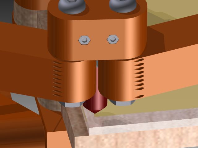
Here you can see helical holes at the end of these arms to do the double lamina setup that is discussed previously.
Todo: (Jump in if you have any ideas on these items.)
Edited 1 time(s). Last edit at 06/28/2013 12:13PM by nicholas.seward.

Almost there.

Here you can see helical holes at the end of these arms to do the double lamina setup that is discussed previously.
Todo: (Jump in if you have any ideas on these items.)
- Come up the how this will stand up.
- Figure out where to put the electronics.
- Put a spool holder on the back.
- Make and mount a filament drive.
- Verify that this setup can produce the holding forces needed.
Edited 1 time(s). Last edit at 06/28/2013 12:13PM by nicholas.seward.
|
Re: Tri-Polar Bot Concept -- Meet Wally June 28, 2013 12:18PM |
Registered: 13 years ago Posts: 301 |
|
Re: Tri-Polar Bot Concept -- Meet Wally June 28, 2013 12:23PM |
Registered: 10 years ago Posts: 979 |
|
Re: Tri-Polar Bot Concept -- Meet Wally June 28, 2013 03:57PM |
Registered: 13 years ago Posts: 301 |
|
Re: Tri-Polar Bot Concept -- Meet Wally June 28, 2013 05:04PM |
Registered: 10 years ago Posts: 100 |
I am loving the movies of this! Well done!
[*] Come up the how this will stand up.
If you make the board a little wider, you can put a swing forward dowel rod at the edge from just below where the arms swing out, since all the weight is forward.
If you make the board a bit longer at the bottom, you can make a swing out (90 deg), foot on one or both sides.
[*] Figure out where to put the electronics.
Make the board a bit longer at the bottom and put them below the platform, and away from the heat of a bed or hot end(s).
Another thought is to put a standoff piece of square metal tubes running vertically that would attach to the board, making it stiffer, and that the plastic parts would screw onto. This is dirt cheap material. This would do two things. First, it would stabilize the board and parts. Second, it would provide a standoff which would create a gap between the board and the moving parts. All the electronics and wiring could be put into that gap at some point. Wires could also be run inside the channels.
Another approach to stiffen the board is to just put angle metal around the edges at the back. Another strip off the board could be used to build up a bit of standoff.
Square metal tubes could be put on the back side, creating a hole for the electronics below or under the spool. That would also keep the electronics away from the heat of a heated bed or hot end(s). They would be very accessible. If the board does not need stabilizing, plastic square tubes could be used, or perhaps just at the corners and middle.
The board could be made taller and the electronics put above the action and it would also be very close to the motors to make the wiring more direct (front or back).
|
Re: Tri-Polar Bot Concept -- Meet Wally June 29, 2013 02:04AM |
Registered: 11 years ago Posts: 248 |

|
Re: Tri-Polar Bot Concept -- Meet Wally June 29, 2013 02:08AM |
Registered: 10 years ago Posts: 979 |
|
Re: Tri-Polar Bot Concept -- Meet Wally June 29, 2013 07:49PM |
Have you seen RepRap-Lewis ?
|
Re: Tri-Polar Bot Concept -- Meet Wally June 30, 2013 04:48PM |
|
Re: Tri-Polar Bot Concept -- Meet Wally June 30, 2013 07:09PM |
Registered: 10 years ago Posts: 979 |
|
Re: Tri-Polar Bot Concept -- Meet Wally July 01, 2013 09:34AM |
Registered: 10 years ago Posts: 979 |
DaveT Wrote:
-------------------------------------------------------
> Have you seen RepRap-Lewis ?
Very interesting. I have never seen the Lewis before. Do you know if it has been physically prototyped?
Edit:
Found this pic.
It looks like the development stopped or went underground.
Edited 3 time(s). Last edit at 07/01/2013 06:46PM by nicholas.seward.
-------------------------------------------------------
> Have you seen RepRap-Lewis ?
Very interesting. I have never seen the Lewis before. Do you know if it has been physically prototyped?
Edit:
Found this pic.

It looks like the development stopped or went underground.
Edited 3 time(s). Last edit at 07/01/2013 06:46PM by nicholas.seward.
|
Re: Tri-Polar Bot Concept -- Meet Wally July 02, 2013 03:24AM |
Registered: 10 years ago Posts: 979 |

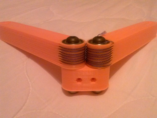
I made a mockup/prototype of the DLCJ (double lamina compliant joint). It worked beautifully. For limited rotational motion transmission, this is the way to go. Very low friction. No noise. No backlash.
I made some mistakes in my design so I will have to reprint those three parts for the real Wally. The helical holes were a bad idea. I am going to have hooks that will let the string make a 90 degree turn and then go up and over the arm. This should allow for fast and easy lacing of the string. I also need to have a piece of plastic on the top that runs over the strings and can press them down into a recess to tension the joint.
I even made a mistake on the stub arm. One of its holes is 1mm bigger than the other. Damn robots do exactly what you tell them instead of what you want.
I made a video showing and explaining the DLCJ.
http://www.youtube.com/watch?v=waNj4ZMftT4
Edited 1 time(s). Last edit at 07/02/2013 03:26AM by nicholas.seward.
|
Re: Tri-Polar Bot Concept -- Meet Wally July 02, 2013 04:31PM |
Registered: 10 years ago Posts: 100 |
Thanks for that great video update. Seeing your progress is actually giving me goosebumps! Go, Go, Go!
I really like how well that joint worked.
Instead of the string going up and over the top, it might be better to have a series of through holes back a bit further from the bearing, so that the strings are still in a straight line for a good straight tension. The hole can be large enough to pass a simple wire needle through with the string tied to it and a 45 deg or radius countersink to keep from having a sharp edge. This really is a sewing seam, so why not needle and thread? You could even put a small spring on the arm further back to keep a constant tension on the string.
The inverse kinematics is an interesting problem. I just spent months trying to figure out how to find an solution for a n-folded hydro-pneumatic system. Took me 3 start over tries to get on the right track (this is not my area of expertise). It was like inventing from scratch for me. Then today I looked up inverse kinematics on Wikipedia and found out that was close to what I was doing, including the iterative solution approaches. LOL
I wonder how much easier the problem would be if you reduced the number of joints so that the arms came together to one point (like Simpson), and the effector always pointed straight to the backboard with just an offset. The offset has to be done anyway due to the offset in the Z axis motion.
I will go out on a limb and say that the best electronics for Wally is an ARM chip with a high clock speed and hardware floating point. I know there is work being done on this. The number crunching available should make a big difference. The cost of these ARM chips is pretty low.
You might have already decided to do this: Make the elbow pulley a separate print for the prototypes. That way you can change the ratio or string configuration without having to reprint and lace up the whole arm each iteration.
I suppose Wally needs to have a large enough print area to be able to replicate itself.
This is really exciting to me to see how fast and far you are taking this. :-)
I really like how well that joint worked.
Instead of the string going up and over the top, it might be better to have a series of through holes back a bit further from the bearing, so that the strings are still in a straight line for a good straight tension. The hole can be large enough to pass a simple wire needle through with the string tied to it and a 45 deg or radius countersink to keep from having a sharp edge. This really is a sewing seam, so why not needle and thread? You could even put a small spring on the arm further back to keep a constant tension on the string.

The inverse kinematics is an interesting problem. I just spent months trying to figure out how to find an solution for a n-folded hydro-pneumatic system. Took me 3 start over tries to get on the right track (this is not my area of expertise). It was like inventing from scratch for me. Then today I looked up inverse kinematics on Wikipedia and found out that was close to what I was doing, including the iterative solution approaches. LOL
I wonder how much easier the problem would be if you reduced the number of joints so that the arms came together to one point (like Simpson), and the effector always pointed straight to the backboard with just an offset. The offset has to be done anyway due to the offset in the Z axis motion.
I will go out on a limb and say that the best electronics for Wally is an ARM chip with a high clock speed and hardware floating point. I know there is work being done on this. The number crunching available should make a big difference. The cost of these ARM chips is pretty low.
You might have already decided to do this: Make the elbow pulley a separate print for the prototypes. That way you can change the ratio or string configuration without having to reprint and lace up the whole arm each iteration.
I suppose Wally needs to have a large enough print area to be able to replicate itself.
This is really exciting to me to see how fast and far you are taking this. :-)
|
Re: Tri-Polar Bot Concept -- Meet Wally July 02, 2013 04:48PM |
Registered: 10 years ago Posts: 979 |
If I use Simpson Proto 1 arms the math is pretty easy and I could squeeze it into Firmware if I got some help from people that do that sort of thing all the time. I will see how many mathematical operations I will have to do for the iterative approach. It might be something that can be done in Firmware. If not, a custom Slic3r would be pretty easy to do.
I am stuck with an Azteeg X1 for control. It uses a Atmel ATMEGA1284P but that is meaningless to me. I am not a hardware guy. (I stick the math in firmware if possible. If not, oh well.)
I like your arm design. However, I have already printed one of the replacement arms and am now printing the other. I will use your design if my external grooves don't work.
I am going to stick with the DLCJ for now. 1) It is awesome. 2) It is cheaper. 3) Multiple extruders/atc capable. 4) symmetry


Sorry, only registered users may post in this forum.