New polar concept/design
Posted by Gomez.Marcos
|
New polar concept/design December 17, 2013 04:11PM |
Registered: 10 years ago Posts: 226 |
Hello,
Well first of all, I'm from Argentina and my english isn't the best
I come to the design at my obsession to get my first printer that because of problems with importation in mi country its really difficult to get one. I had centered on the price (quantity of parts and availability), relation between printing zone and printer volumen, possibility of adding a 3d scanner and avoiding classic thread rods and belts.
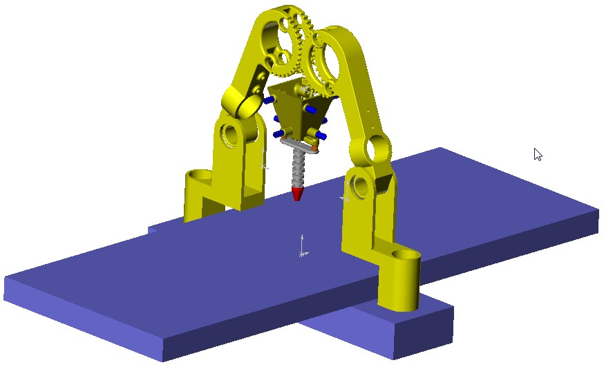
It has delta based module-z axis and polar radius. I gave dimensions to fit a printing cylinder of diameter of 280 and 200 height. with heatbed also
I want to hear all possible improvements and problems that it could have, based in your experience, i remind you that I have never had a printer
That is just a concept drawing:
Well first of all, I'm from Argentina and my english isn't the best
I come to the design at my obsession to get my first printer that because of problems with importation in mi country its really difficult to get one. I had centered on the price (quantity of parts and availability), relation between printing zone and printer volumen, possibility of adding a 3d scanner and avoiding classic thread rods and belts.
It has delta based module-z axis and polar radius. I gave dimensions to fit a printing cylinder of diameter of 280 and 200 height. with heatbed also
I want to hear all possible improvements and problems that it could have, based in your experience, i remind you that I have never had a printer
That is just a concept drawing:

|
Re: New polar concept/design December 17, 2013 04:57PM |
Registered: 13 years ago Posts: 485 |
Straight lines passing near the table center are going to need very high angular velocity and acceleration.
I'm not sure if any firmware support this configuration. Will you be able to modify firmware to make this work?
You will have much greater chances of success building an established design, I think.
I'm not sure if any firmware support this configuration. Will you be able to modify firmware to make this work?
You will have much greater chances of success building an established design, I think.
|
Re: New polar concept/design December 17, 2013 05:20PM |
Registered: 10 years ago Posts: 226 |
Quote
Dale Dunn
Straight lines passing near the table center are going to need very high angular velocity and acceleration.
I'm not sure if any firmware support this configuration. Will you be able to modify firmware to make this work?
You will have much greater chances of success building an established design, I think.
yes, its true i must keep constant the tangencial velocity
I have programming knowledges, so yes, its in my todo list
I have no problem in failling, I like to innovate and never is done at first try
|
Re: New polar concept/design December 17, 2013 05:39PM |
Registered: 10 years ago Posts: 100 |
|
Re: New polar concept/design December 17, 2013 05:42PM |
Registered: 10 years ago Posts: 1,381 |
|
Re: New polar concept/design December 17, 2013 05:59PM |
Registered: 10 years ago Posts: 226 |
Quote
see3d
Your arms are much like "Wally" arms, but vertical instead of horizontal. You may be able to adapt some of the design details proposed for Wally.
I'm going to take a look
Quote
A2
Cut the table in half, and only use a half circle (save space), or add a second set of arms and print 2 parts at the same time.
Off set the arms from the center of the table to avoid the singularity.
It would be neat to be able to tilt the platen to print overhangs.
I can move the end in both directions, so i can print on the complete 280 diameter circle
if I cut the table i will be loosing a lot of print volume, and not really saving too much space
I see it really difficult now, but I like the idea
|
Re: New polar concept/design December 17, 2013 09:08PM |
Registered: 10 years ago Posts: 100 |
|
Re: New polar concept/design December 17, 2013 10:48PM |
Registered: 10 years ago Posts: 979 |
How do you plan to keep the effector level? I have a similar project bouncing around in my head but it is 4 degrees of freedom. I was going to use 3 proportional gear drive joints. [www.youtube.com]
|
Re: New polar concept/design December 18, 2013 12:58AM |
Registered: 10 years ago Posts: 226 |
if you give the correct angles to the arms, it keep in levelQuote
nicholas.seward
How do you plan to keep the effector level? I have a similar project bouncing around in my head but it is 4 degrees of freedom. I was going to use 3 proportional gear drive joints. [www.youtube.com]
if the print volumen is small it can be done in half plate... yes is not the best for 90° but the reason of using polar is the possibility of adding a 3d scanner in futureQuote
see3d
Printing with a full circle is great for certain things. A gear, a vase, a snowflake, and anything with a radial center point. Things made of 90 degree walls would print best on a Cartesian mechanism.
|
Re: New polar concept/design December 18, 2013 10:26AM |
Registered: 10 years ago Posts: 979 |
@Gomez.Marcos: What joints are you going to actuate? The geometry of the system dictates that you actuate 3 of the joints. (If you are going to do that you might as well go for a 4 degree of freedom robot.) I attached a diagram below that would show how you can still do this but only use 2 actuators.

|
Re: New polar concept/design December 18, 2013 10:58AM |
Registered: 10 years ago Posts: 226 |
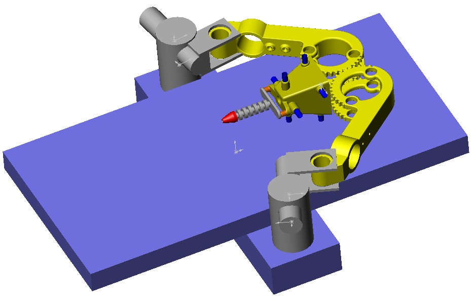
here can be seen... I have static actuators in bottom of arms
I dont see why the level would change
I would like if you can explain it
or when you say 2 actuators are you also counting the bed's one?
I dont see why the level would change
I would like if you can explain it

or when you say 2 actuators are you also counting the bed's one?
|
Re: New polar concept/design December 18, 2013 01:19PM |
Registered: 10 years ago Posts: 979 |

@Gomez.Marcos: I attached an animation of the problem you will have. There are a few solutions.
*Add the parallel linkage similar to the one in my previous post.
*Actuate another joint to fully constrain the position. (This will drastically increase the complexity of the firmware/software and will require a more expensive controller. However, you now have a 4 DOF robot!)
*Add an active gyroscopic stabilizer. (By far the coolest option but requires lots of research.)
You also won't have enough torque or precision to drive the motor arm directly with a standard NEMA17 stepper. You will need some pulleys or a worm drive for example.
Note: Please accept these comments as ways in which to make this project successful and not as discouragement. I sincerely hope you carry on with this project. I think a printer of this format has much potential. I have been dying to try one but I have a laundry list of tasks to do before I can even think about it.
|
Re: New polar concept/design December 18, 2013 02:22PM |
Registered: 10 years ago Posts: 226 |
I have thought about this movement, but if the angular position of both arms is the correct, its not supposed to do that
for example end of left arm never could be at right of the right end
I already have the maths :
and about torque and precision I pretend to use 0,9° stepper with standard microstepping drivers a4988
no idea about torque needed , considering that obviously has a bowden extruder and the weight distributed between both motors
I think that it could be a 4 dof with those maths
if you haven't noticed, no one is going to discourage me jaja
for example end of left arm never could be at right of the right end
I already have the maths :

and about torque and precision I pretend to use 0,9° stepper with standard microstepping drivers a4988
no idea about torque needed , considering that obviously has a bowden extruder and the weight distributed between both motors
I think that it could be a 4 dof with those maths
if you haven't noticed, no one is going to discourage me jaja
|
Re: New polar concept/design December 18, 2013 04:44PM |
Registered: 10 years ago Posts: 979 |
@Gomez.Marcos:
There is is not much difference between a 1/16 micro stepping 0.9 degree stepper and a 1/32 micro stepping 1.8 degree stepper. (I seem to recall from somewhere in my brain that with all other things equal the 1.8 degree stepper will have more torque at speed.)
If I had to guess you would need a mechanical advantage of 5-10 even with the bowden setup. This is not because you need the torque. You need it for the precision.
Even in the situation you have in the diagram you still are not constrained. I really wish it is was because that would make life easier. In the situation that you have with the base angles constrained the elbows are essentially grounded joints. That leaves you with a 4 bar linkage.
Edited 1 time(s). Last edit at 12/18/2013 04:56PM by nicholas.seward.
There is is not much difference between a 1/16 micro stepping 0.9 degree stepper and a 1/32 micro stepping 1.8 degree stepper. (I seem to recall from somewhere in my brain that with all other things equal the 1.8 degree stepper will have more torque at speed.)
If I had to guess you would need a mechanical advantage of 5-10 even with the bowden setup. This is not because you need the torque. You need it for the precision.

Even in the situation you have in the diagram you still are not constrained. I really wish it is was because that would make life easier. In the situation that you have with the base angles constrained the elbows are essentially grounded joints. That leaves you with a 4 bar linkage.
Edited 1 time(s). Last edit at 12/18/2013 04:56PM by nicholas.seward.
|
Re: New polar concept/design December 18, 2013 05:49PM |
Registered: 10 years ago Posts: 226 |
|
Re: New polar concept/design December 18, 2013 10:36PM |
Registered: 10 years ago Posts: 226 |
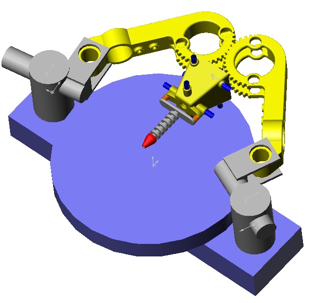
with level correction:
I'm considering the idea of tilt the platen but it would need completely new g-code processor software


I'm considering the idea of tilt the platen but it would need completely new g-code processor software
|
Re: New polar concept/design December 19, 2013 02:19AM |
Registered: 10 years ago Posts: 1,381 |
@Gomez.Marcos, engineer a gimbal bot to preform minor surgeries!
The world needs a personal surgeon bot
I can design the surgical instruments for surgeebot
I'm sitting on a design for a needle driver that is suited for robot manipulation.
Ballz Bot, 5 DOF Bobot
[www.youtube.com]
In Ruben Brewer lecture, he mentions that this is an ideal platform, less a few inconveniences for surgery.
It would be useful for an arm or leg operation, not the torso, as the gimbal would get in the way.
CS235, Lecture 13-Rigid Linkages, Spherical Bearings, Remote-Center-of-Motion, and Counterbalances
[www.youtube.com]
Edited 1 time(s). Last edit at 12/19/2013 02:20AM by A2.
The world needs a personal surgeon bot
I can design the surgical instruments for surgeebot
I'm sitting on a design for a needle driver that is suited for robot manipulation.

Ballz Bot, 5 DOF Bobot
[www.youtube.com]
In Ruben Brewer lecture, he mentions that this is an ideal platform, less a few inconveniences for surgery.
It would be useful for an arm or leg operation, not the torso, as the gimbal would get in the way.
CS235, Lecture 13-Rigid Linkages, Spherical Bearings, Remote-Center-of-Motion, and Counterbalances
[www.youtube.com]
Edited 1 time(s). Last edit at 12/19/2013 02:20AM by A2.
|
Re: New polar concept/design December 19, 2013 09:39AM |
Registered: 10 years ago Posts: 979 |
|
Re: New polar concept/design December 19, 2013 09:41AM |
Registered: 10 years ago Posts: 226 |

|
Re: New polar concept/design December 19, 2013 01:08PM |
Registered: 10 years ago Posts: 226 |
|
Re: New polar concept/design December 19, 2013 05:23PM |
Registered: 10 years ago Posts: 226 |
|
Re: New polar concept/design December 20, 2013 05:15AM |
Registered: 10 years ago Posts: 979 |
I haven't messed with firmware much but I believe there is one function in Marlin that you can modify if you want to do coordinate transformations. However, most controllers will probably chock on the amount of computation that this will require. You would need a controller with an ARM processor.
When I do testing I just use a hobbled together gcode preprocessor. This lets me use unmodified firmware. Here is a link to a glitchy but functional preprocessor that I use. It breaks the gcode down into 1mm segments and does transformations on all the little segments. It is brute force. I know there are lots of optimizations that can be made.
Here is what I mean about strings in tension. In fact, the way I have it drawn you can use 1 string. I would wrap around each yellow pulley a few time to make sure there is enough friction. I would put a stiff spring somewhere in series with the string and would also use a guitar tuner to tension the system.
One beautiful thing about this system is you can mount the effector straight to the central pulley. Another crazy side benefit is you could put a stepper in the loop and use this to drive the angle of the effector. You can design the printer to be easily upgradable to 4DOFs.
If you actuate the shoulder joints then the forearms can not go past being parallel to each other. This essentially eliminates 1/2 of the possible height. I would suggest that you actuate the elbows. If you already use one pulley for the string that keeps the effector vertical what is another pulley for driving the elbow joint angle. As much as I like Wally's static steppers, I would suggest that you mount the steppers low on the arms. The performance hit you will get from this extra inertia will be very small.
I had one super crazy idea. I am pretty sure that this won't fit with what you want to do but what if you used a lazy susan and made a huge donut shaped print bed. This will remove the nasty singularity in the middle of the bed and will allow you to print some super long things. If I had to guess, this printer would take up 600mm x 700mm. (This is for a 200mm ID and a 600mm OD of the donut.) To give you an idea of just how big of a thing you could print, I was able to squeeze a random 75mm wide x 475mm long x 250mm tall print onto the bed.
Dang it! Now there is another printer I want to build. BTW, If I did, I would probably use GUS style arms. The GUS arms have virtual pivots in the center of the gear part of the arm. You could put your pulleys there that are needed for string routing to right the effector. The math to position a GUS arm only requires the Pythagorean theorem.
When I do testing I just use a hobbled together gcode preprocessor. This lets me use unmodified firmware. Here is a link to a glitchy but functional preprocessor that I use. It breaks the gcode down into 1mm segments and does transformations on all the little segments. It is brute force. I know there are lots of optimizations that can be made.

Here is what I mean about strings in tension. In fact, the way I have it drawn you can use 1 string. I would wrap around each yellow pulley a few time to make sure there is enough friction. I would put a stiff spring somewhere in series with the string and would also use a guitar tuner to tension the system.
One beautiful thing about this system is you can mount the effector straight to the central pulley. Another crazy side benefit is you could put a stepper in the loop and use this to drive the angle of the effector. You can design the printer to be easily upgradable to 4DOFs.
If you actuate the shoulder joints then the forearms can not go past being parallel to each other. This essentially eliminates 1/2 of the possible height. I would suggest that you actuate the elbows. If you already use one pulley for the string that keeps the effector vertical what is another pulley for driving the elbow joint angle. As much as I like Wally's static steppers, I would suggest that you mount the steppers low on the arms. The performance hit you will get from this extra inertia will be very small.

I had one super crazy idea. I am pretty sure that this won't fit with what you want to do but what if you used a lazy susan and made a huge donut shaped print bed. This will remove the nasty singularity in the middle of the bed and will allow you to print some super long things. If I had to guess, this printer would take up 600mm x 700mm. (This is for a 200mm ID and a 600mm OD of the donut.) To give you an idea of just how big of a thing you could print, I was able to squeeze a random 75mm wide x 475mm long x 250mm tall print onto the bed.
Dang it! Now there is another printer I want to build. BTW, If I did, I would probably use GUS style arms. The GUS arms have virtual pivots in the center of the gear part of the arm. You could put your pulleys there that are needed for string routing to right the effector. The math to position a GUS arm only requires the Pythagorean theorem.
|
Re: New polar concept/design December 20, 2013 03:15PM |
Registered: 13 years ago Posts: 485 |
|
Re: New polar concept/design December 20, 2013 03:41PM |
Registered: 10 years ago Posts: 226 |
Wow i like both ideas the pulleys, are great and really easy to do a 4DOF
it was difficult to understand the movement, i think that is only needed pulley friction in the effector, right?
the parallel arms is a problem, I can play with arms long, but this is going to decrease precision that is about 200 microns in low border and 250 in high center(without mechanical advantage)
Yes, its against my first point that was the possibility of adding 3d scanner :/ and would be huge
while thinking, came to me the idea of a 6 DOF rotatory platen,it would be colossal, with static effector giving milling possibility , and obviously 3D scanner lol
maybe the next machine...
how much print volume give your GUS arms??
about firmware, I'm going to customize Repetier I get some tips about how to do it
is still huge only with the effective part (660:OD 100:ID)
Edited 1 time(s). Last edit at 12/20/2013 04:03PM by Gomez.Marcos.
it was difficult to understand the movement, i think that is only needed pulley friction in the effector, right?
the parallel arms is a problem, I can play with arms long, but this is going to decrease precision that is about 200 microns in low border and 250 in high center(without mechanical advantage)
Yes, its against my first point that was the possibility of adding 3d scanner :/ and would be huge
while thinking, came to me the idea of a 6 DOF rotatory platen,it would be colossal, with static effector giving milling possibility , and obviously 3D scanner lol
maybe the next machine...
how much print volume give your GUS arms??
about firmware, I'm going to customize Repetier I get some tips about how to do it

is still huge only with the effective part (660:OD 100:ID)
Edited 1 time(s). Last edit at 12/20/2013 04:03PM by Gomez.Marcos.
|
Re: New polar concept/design December 20, 2013 06:41PM |
Registered: 10 years ago Posts: 226 |
with shorter secondary arms (210/250) I improved precision(from 200 to 40) and height when primary are parallel still without mechanical advantage
I think that I am doing wrong the maths, someone can calculate if its true?
there is an error on this formule where it says "x+B+b-Exl" is "B+b-x-Exl" (3 times)
dimensions:
L=250mm
l=210mm
h=0
B=190mm
b=140mm
Exl=0
Exh=3
I think that I am doing wrong the maths, someone can calculate if its true?
there is an error on this formule where it says "x+B+b-Exl" is "B+b-x-Exl" (3 times)
dimensions:
L=250mm
l=210mm
h=0
B=190mm
b=140mm
Exl=0
Exh=3
|
Re: New polar concept/design December 20, 2013 07:14PM |
Registered: 10 years ago Posts: 1,381 |

|
Re: New polar concept/design December 20, 2013 07:39PM |
Registered: 10 years ago Posts: 226 |
|
Re: New polar concept/design December 20, 2013 09:03PM |
Registered: 10 years ago Posts: 1,381 |
OK, yes you need the scanner.
How about you put it on a gimbal, we're get closer to SurgeeBot
Table can be linear, and/or revolute pivot, (i.e combination of both).
Edited 4 time(s). Last edit at 12/20/2013 09:11PM by A2.
How about you put it on a gimbal, we're get closer to SurgeeBot
Table can be linear, and/or revolute pivot, (i.e combination of both).


Edited 4 time(s). Last edit at 12/20/2013 09:11PM by A2.
|
Re: New polar concept/design December 20, 2013 09:41PM |
Registered: 10 years ago Posts: 226 |
|
Re: New polar concept/design December 20, 2013 09:51PM |
Registered: 10 years ago Posts: 1,381 |
I count 4 DOF's, not counting the gimbal pivot moving in, and out.
Arms = up/dn + in/out. = 2.
Gimbal swing side to side = 1.
Table revolute pivot = 1.
I can see that the way I have it drawn that one might think that the shoulder pivot also moves in, and out, which would add another DOF.
But I don't think that is needed, but it would be fun to watch it if you did add it (I bet it'll burn some brain cells if you did add it) .
.
You could also add a pan/tilt to the table.
You could spin the extruder.
Arms = up/dn + in/out. = 2.
Gimbal swing side to side = 1.
Table revolute pivot = 1.
I can see that the way I have it drawn that one might think that the shoulder pivot also moves in, and out, which would add another DOF.
But I don't think that is needed, but it would be fun to watch it if you did add it (I bet it'll burn some brain cells if you did add it)
.You could also add a pan/tilt to the table.
You could spin the extruder.

Sorry, only registered users may post in this forum.