Wally Z axis alternative linear designs
Posted by see3d
|
Wally Z axis alternative linear designs January 18, 2014 12:36AM |
Registered: 10 years ago Posts: 100 |
During the early development brainstorming for the Wally "Tri-Polar" bot, and recently again, the idea of a linear Z axis has come up.
There are a couple of desirable properties of some linear designs.
1) There would be no interaction between the Z and Y axis, making the code simpler and increasing the build volume.
2) The Z axis might be able to be designed so that the length of the Z axis is mainly just lengthening some of the supporting non-printed elements, like the back boards and supports.
Simplicity and low cost have always been important Wally goals. A linear Z axis should enhance these goals, not detract from them.
There may also be other considerations.
Properties 1 & 2 above could be design goals, however, this thread is specifically for brainstorming the Z axis, so it is not strictly constrained to just goals 1 & 2. There may be other interesting Z ideas that have their own advantages worth considering.
For reference, some discussions took place in this external thread with several contributing to some linear Z ideas for Wally:
[forum.conceptforge.org]
I also initiated some private email brainstorming with Nicholas Seward. It was his suggestion to start this thread to open up the process to all.
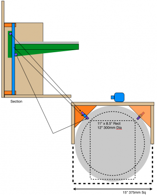
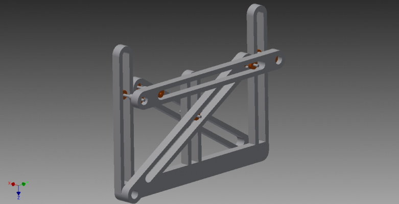
To start off with something, here is my last idea, but perhaps not the best idea. It is based on two vertical square rails with circular build platform riding up and down with a total of 4 bearings in a cantilevered gravity loading. The actual Z height control would come from a belt, string, or lead screw driven by a stepper. The rails would actually be coming off the corners of the back/side boards. Those are the most rigid points along the Z axis.
Here is a simplified block diagram of the placement of the components (based on having a larger 300mm printable diameter Wally):
|
Re: Wally Z axis alternative linear designs January 18, 2014 03:46PM |
Registered: 10 years ago Posts: 226 |
maybe a pair of smooth rods and a differential pulley? will not increase costs, with good resolution and without y movements
differential pulley formulas
[www.engineersedge.com]
Edited 1 time(s). Last edit at 01/18/2014 03:48PM by Gomez.Marcos.
differential pulley formulas
[www.engineersedge.com]
Edited 1 time(s). Last edit at 01/18/2014 03:48PM by Gomez.Marcos.
|
Re: Wally Z axis alternative linear designs January 18, 2014 07:16PM |
Registered: 11 years ago Posts: 1,049 |
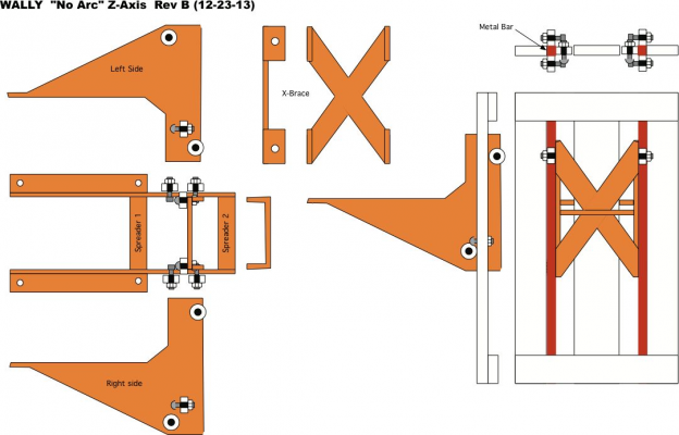
Design from Concept forge site
starts with this post
[forum.conceptforge.org]
message
[forum.conceptforge.org]
has refined 3D concept of the "Noarc" design

starts with this post
[forum.conceptforge.org]
message
[forum.conceptforge.org]
has refined 3D concept of the "Noarc" design

|
Re: Wally Z axis alternative linear designs January 18, 2014 07:17PM |
Registered: 10 years ago Posts: 10 |
Almost tempted to buy one of these and hack a stepper motor onto it 
Laboratory Scissors Jack
But, I think we'll see if we can beat the exisitng design into submission first.
Edited 1 time(s). Last edit at 01/18/2014 07:19PM by smooshed.

Laboratory Scissors Jack
But, I think we'll see if we can beat the exisitng design into submission first.
Edited 1 time(s). Last edit at 01/18/2014 07:19PM by smooshed.
|
Re: Wally Z axis alternative linear designs January 18, 2014 07:36PM |
Registered: 10 years ago Posts: 167 |
|
Re: Wally Z axis alternative linear designs January 18, 2014 07:48PM |
Registered: 10 years ago Posts: 226 |
the differential pulley would keep using string, will not suggest more changes than the rods (that is needed for any linear system) and motor pulley by a dual of different radius
I have no time to do models because I'm with another machine also
I cannot register in concept-forge it says that my ip is blacklisted
Edited 1 time(s). Last edit at 01/18/2014 07:50PM by Gomez.Marcos.
I have no time to do models because I'm with another machine also
I cannot register in concept-forge it says that my ip is blacklisted

Edited 1 time(s). Last edit at 01/18/2014 07:50PM by Gomez.Marcos.
|
Re: Wally Z axis alternative linear designs January 19, 2014 03:46PM |
Registered: 10 years ago Posts: 100 |
@Gomez.Marcos -- The current Wally does use a simpler string pulley version with a 2:1 ratio. Thanks for the link to the other differential pulley versions.
A smooth rod (round or square), is not the only option for a linear Z, but it is easy to see how it can be extended to any Z length. However, the longer the unsupported Z length for a rod, the stiffer it needs to be to keep the motion straight. This can be done by using hollow square or round tubes instead of solid ones, or using stiffer materials.
Another idea is that it could be done with an angle "L" rod so that it can tie back to more support points at the backboard corners for greater strength with a thin and low cost metal part. A lot of room for creativity on how to do this one to make it good, practical, and cheap.
@cozmicray -- Thanks for bringing the relevant posts from the CF forum to this thread.
@ smooshed, AbuMaia -- A Scissor Jack is printable. It still requires a threaded rod, and is somewhat complex looking. It looks like it would not be a linear relationship between steps and Z change from any random starting position. What would be the advantages that would make it attractive to you?
Thanks for all the posts. We are off to a good start on different ideas. We are only limited by our pre-conceived ideas.

|
Re: Wally Z axis alternative linear designs January 19, 2014 10:04PM |
Registered: 10 years ago Posts: 979 |
|
Re: Wally Z axis alternative linear designs January 19, 2014 10:40PM |
Registered: 10 years ago Posts: 226 |
@see3d:differential pulleys are two different radius on the same axis, it could increase precision but is not needed right now... je I had never looked in detail wally z movements until now
I think scissors jack is a great idea, maybe can reuse actual arms and bearings to do it
z axis goes down when the stepper is free?
now I could register
I think scissors jack is a great idea, maybe can reuse actual arms and bearings to do it
z axis goes down when the stepper is free?
now I could register
|
Re: Wally Z axis alternative linear designs January 19, 2014 11:03PM |
Registered: 10 years ago Posts: 100 |
@Gomez.Marcos -- Yes, a scissor jack would not allow the Z to fall, which could happen with the current Wally design if the motor detent was too weak, or the string broke.
OTOH, having the Z drop in a controlled way is a way to set the end stop without needing switches. A scissor jack might need a switch. It has very poor resolution at the bottom and very fine resolution at the top. You also have to stack many stages to get longer Z. Perhaps there are alternative ways to do a scissor jack that does not have these problems?
It might be possible to have a way to "catch" the table at the bottom so it does not "crash". I can think of a few ways already.
If a lead screw was used for the Z, it would also not crash, and be simpler, lower cost, and easy to program.
Quote
Gomez.Marcos
@see3d:
I think scissors jack is a great idea, maybe can reuse actual arms and bearings to do it
z axis goes down when the stepper is free?
|
Re: Wally Z axis alternative linear designs January 20, 2014 12:33AM |
Registered: 10 years ago Posts: 226 |
|
Re: Wally Z axis alternative linear designs January 20, 2014 03:01AM |
Registered: 10 years ago Posts: 979 |
First, I need to test a simplified version of the Compact Space Crank. I would try it with one arm per side with just the two sides supported. I am sure it won't work but I am curious just how bad it will preform. I assume that the doubled up arm version in the video will be around twice as rigid. I don't think it will be good enough either but I am still curious.
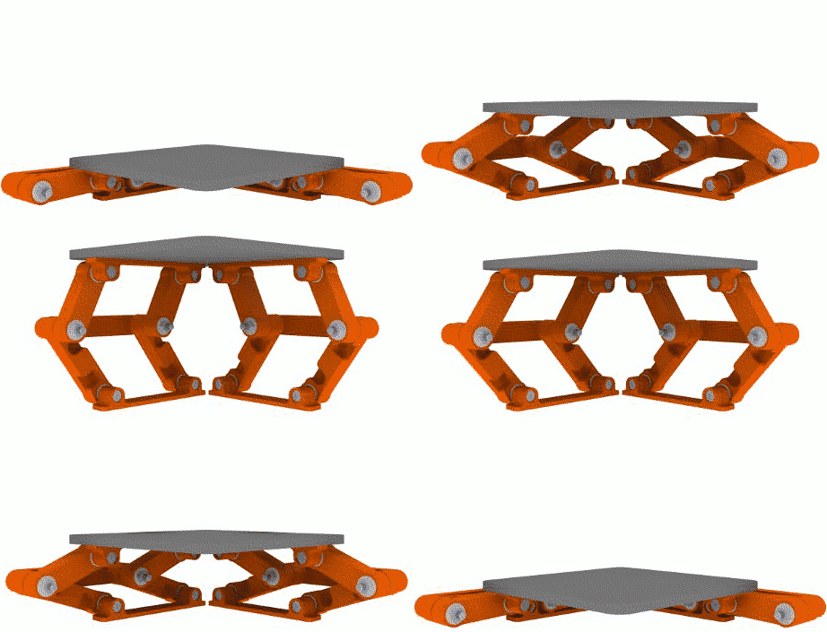
I have been knocking around another space crank that used parallelograms to square up the table in both directions. The typical problem with a space crank is that it isn't very rigid where you need it to be. The design below is not very rigid in registering the table in the x and y direction but it is very rigid when it comes to it rotating about the x or y axis. That is ideal for our situation. We don't have any large side forces on the platform.
After doing this design, I realized I could go back to the Compact Space Crank and just have a connecting plate between the elbows. This will allow you to use really stubby arms for a pretty substantial range of motion. The arms segments only have to be a little over 1/4 of the overall target range.
In closing, I guess I will try out the Compact Space Crank with the added connection plate to get the support of the parallelograms.
BTW, this design uses 32 608's. That sounds like a lot and it is but the overall costs are right around $10 for this z stage when the bearings are less than 25 cents a piece. It would be hard to get 1 metal rod for that price.
Edited 1 time(s). Last edit at 01/20/2014 03:08AM by nicholas.seward.
|
Re: Wally Z axis alternative linear designs January 20, 2014 12:08PM |
Registered: 11 years ago Posts: 1,049 |
|
Re: Wally Z axis alternative linear designs January 20, 2014 12:30PM |
Registered: 10 years ago Posts: 979 |
@cozmicray: Agreed that I could simplify. However, my personal requirement is that I use no linear guides. Anyways, that is just to just open up our minds and get us thinking. Opening bid if you will.
I would drive this just like I drive Wally's bed.
Btw, you can keep the motors from turning off during a print and for me the crash after the motors go off it is audible but not destructive. You can also turn off the timeout when inactive. Is anything causing you grief?
I would drive this just like I drive Wally's bed.
Btw, you can keep the motors from turning off during a print and for me the crash after the motors go off it is audible but not destructive. You can also turn off the timeout when inactive. Is anything causing you grief?
|
Re: Wally Z axis alternative linear designs January 20, 2014 03:13PM |
Registered: 10 years ago Posts: 100 |
Quote
nicholas.seward
BTW, this design uses 32 608's. That sounds like a lot and it is but the overall costs are right around $10 for this z stage when the bearings are less than 25 cents a piece. It would be hard to get 1 metal rod for that price.
A 0.75 inch square 304 SS tube (0.065 wall), would run about $9.62 for 36 inches. That is about right for a 12 inch (my goal) Z travel. That was just the first place I looked on-line. If that is not stiff enough, a 1 inch square would be about $13. A 0.50 x 1.50 inch Rectangle tube is about $16. For extreme precision, a pair of 0.25 x 0.75 ground tool steel 18 inch long bars would be about $40 a pair.
If you don't mind hot rolled steel tubes, it is about 1/3 the price.
I think there a lot of options for linear bars that do not cost much.
|
Re: Wally Z axis alternative linear designs January 20, 2014 06:26PM |
Registered: 11 years ago Posts: 1,049 |
Why No linear guides?
Is the design I proposed above an "Linear Guide"
Is the design I proposed above an "Linear Guide"
Quote
nicholas.seward
@cozmicray: Agreed that I could simplify. However, my personal requirement is that I use no linear guides. Anyways, that is just to just open up our minds and get us thinking. Opening bid if you will.
I would drive this just like I drive Wally's bed.
Btw, you can keep the motors from turning off during a print and for me the crash after the motors go off it is audible but not destructive. You can also turn off the timeout when inactive. Is anything causing you grief?
|
Re: Wally Z axis alternative linear designs January 20, 2014 06:57PM |
Registered: 10 years ago Posts: 979 |
@Cozmicray: Unless I missed one, all the other designs in this thread need some kind of linear guide. Even the scissor jack needs to have a linear guide at the bottom.
There is nothing wrong with linear guides I encourage anyone that wants to use a linear guide solution to do so. I am self imposing restrictions on my own designs that bar linear guides. (I sometimes break this restriction. For instance, LISA.)
Why would I impose such a restriction? The design I posted above costs $10 and will be quieter, smoother, low friction, and longer lasting than any linear guide solution <$100. (Quite a statement. I would love for someone to prove me wrong.) For me it is a combination of cost and performance. People like linear guides because they are easy to build and think about. I figure if I keep at it, eventually I will hit upon a solutions without linear guides that is simple enough. I think a variation of the design above could do it. Testing is needed.
Again, nothing is wrong with linear guides.
|
Re: Wally Z axis alternative linear designs January 20, 2014 07:35PM |
Registered: 10 years ago Posts: 226 |
|
Re: Wally Z axis alternative linear designs January 20, 2014 09:46PM |
Registered: 10 years ago Posts: 226 |
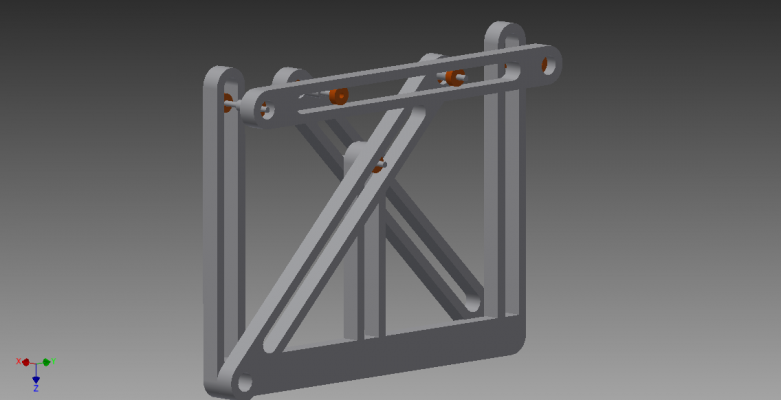
I fast modeled my idea
I call it "jack scissor" jajajjaa
it would need just twelve 608
I call it "jack scissor" jajajjaa
it would need just twelve 608
|
Re: Wally Z axis alternative linear designs January 21, 2014 11:25PM |
Registered: 10 years ago Posts: 100 |
This thread should be about throwing out all kinds of ideas to spark the creative juices.
After we run out of different ideas, then we can focus on the pros and cons of each one. Often times, identifying a weakness in a design, just inspires a creative way around it.
I am using a 300mm Z travel as my design center for evaluating different ideas for size, cost, durability, precision, etc.
|
Re: Wally Z axis alternative linear designs January 23, 2014 12:06PM |
Registered: 10 years ago Posts: 10 |
Since our Wally backboard is made of aluminum, I thought it might be interesting to machine v-slots into it, along the lines of this V-Slot Extrusion.
The backboard itself becomes the guide. I was thinking that even just a four roller carriage might work with a cantilevered bed, two on top in the back and two in front on the bottom. The bed could be tilted up and toward the back, but does that matter?
I don't know if anything like this would work with a plywood of MDF backboard, but maybe with the right wheels it would hold up?
Sorry I don't have a model or a drawing, just thought I should mention this approach in case it clicks with anyone else.
|
Re: Wally Z axis alternative linear designs January 23, 2014 03:07PM |
Registered: 10 years ago Posts: 100 |
|
Re: Wally Z axis alternative linear designs June 09, 2014 05:10PM |
Registered: 9 years ago Posts: 135 |
Sorry for bringing up an old thread, but have you ever considered a Hoekins linkage or its older cousin the Chebyshev linkage?
Both give very nearly perfectly flat, even motion along 180o of the crank's travel. Not as perfectly flat as the Sarrus linkage, but they can both be made much more stable.
Both give very nearly perfectly flat, even motion along 180o of the crank's travel. Not as perfectly flat as the Sarrus linkage, but they can both be made much more stable.
|
Re: Wally Z axis alternative linear designs June 09, 2014 06:05PM |
Registered: 10 years ago Posts: 979 |
I tried many virtual iterations with various straight line mechanisms. So far, they add a far amount of complexity. I haven't given up but for simplicity my next designs will probably have 1 traditional linear stage. I do have a modification on a space crank that I know will work but is too complex for a production machine.
So each joint usually gets 2 bearings. I would love to keep the number of bearings for one stage under 20. The solution I mentioned above needs 32 bearings. (ouch)
ConceptFORGE
Wally, GUS Simpson, LISA Simpson, THOR Simpson, Sextupteron, CoreXZ
So each joint usually gets 2 bearings. I would love to keep the number of bearings for one stage under 20. The solution I mentioned above needs 32 bearings. (ouch)
ConceptFORGE
Wally, GUS Simpson, LISA Simpson, THOR Simpson, Sextupteron, CoreXZ
|
Re: Wally Z axis alternative linear designs June 10, 2014 10:02AM |
Registered: 9 years ago Posts: 135 |
Yeah, I figure by the time you need more than 20 ball bearings, you're better off getting four linear bearings and two rails...
The simplest I can think to get a Chebychev linkage to work still requires 20 bearings, and I'm not sure how stable that would be. I can think of a way to get a Hoekins linkage to work with 16 bearings, but it's more suitable for holding a print head rather than a platform, since it holds the load much further out from the fixed points.
The simplest I can think to get a Chebychev linkage to work still requires 20 bearings, and I'm not sure how stable that would be. I can think of a way to get a Hoekins linkage to work with 16 bearings, but it's more suitable for holding a print head rather than a platform, since it holds the load much further out from the fixed points.
|
Re: Wally Z axis alternative linear designs June 10, 2014 10:36AM |
Registered: 10 years ago Posts: 100 |
So far, I have not seen anything more simple that the original top post suggestion I made. It is only 4 bearings and two square, rectangular, or "L" shaped rods as linear guides. I would like to see some ideas for improving this design concept also.
What are the limitations or concerns about that approach?
How can the rods be constructed to make them more economical?
Should they be supported all the way back to the back plate to make them immune to flexing with a cantilever load?
What are the limitations or concerns about that approach?
How can the rods be constructed to make them more economical?
Should they be supported all the way back to the back plate to make them immune to flexing with a cantilever load?
|
Re: Wally Z axis alternative linear designs June 10, 2014 10:51AM |
Registered: 9 years ago Posts: 135 |
|
Re: Wally Z axis alternative linear designs June 10, 2014 12:24PM |
Registered: 11 years ago Posts: 1,049 |
|
Re: Wally Z axis alternative linear designs June 10, 2014 04:34PM |
Registered: 10 years ago Posts: 100 |
Wally as designed by Nicholas had that as an initial goal, but it was never a limiting goal in my mind, even though I supported this goal for the first Wally version. This thread is about alternative Z axis designs for linear motion. There are no limitations in the possible designs, but goodness criteria are: low cost, accurate, easy to build, scalable, etc. 

Quote
Feign
Practically, there aren't any concerns with it... But part of the goals of the Wally were to have a printer that doesn't use any linear rails. Using L-shaped, square shaped, round or slotted linear rails kind of goes against the point of the puzzle...
|
Re: Wally Z axis alternative linear designs June 11, 2014 09:18AM |
Registered: 9 years ago Posts: 135 |
I guess the 'no rails goal' was pretty much the one big thing I saw in the Wally experiment, since there are other printers that work significantly better, but do so with materials that aren't necessarily universally available.
I understand that the Wally really just doesn't work, it seems like it would take a built-from-scratch firmware to get the coordinate system right, and even then it would be tough to calibrate. Even if the interest existed to do that, I'd rather see that effort go to finishing the Simpson. (It looks like Nicholas is going in this direction as well.)
I at least think the Wally had more potential for the 'no-rails' criteria than the Rhombot... At least there's that.

Sorry, only registered users may post in this forum.
