Robotic arm printer
Posted by galaxyman7
|
Robotic arm printer March 14, 2010 06:10PM |
Registered: 14 years ago Posts: 198 |
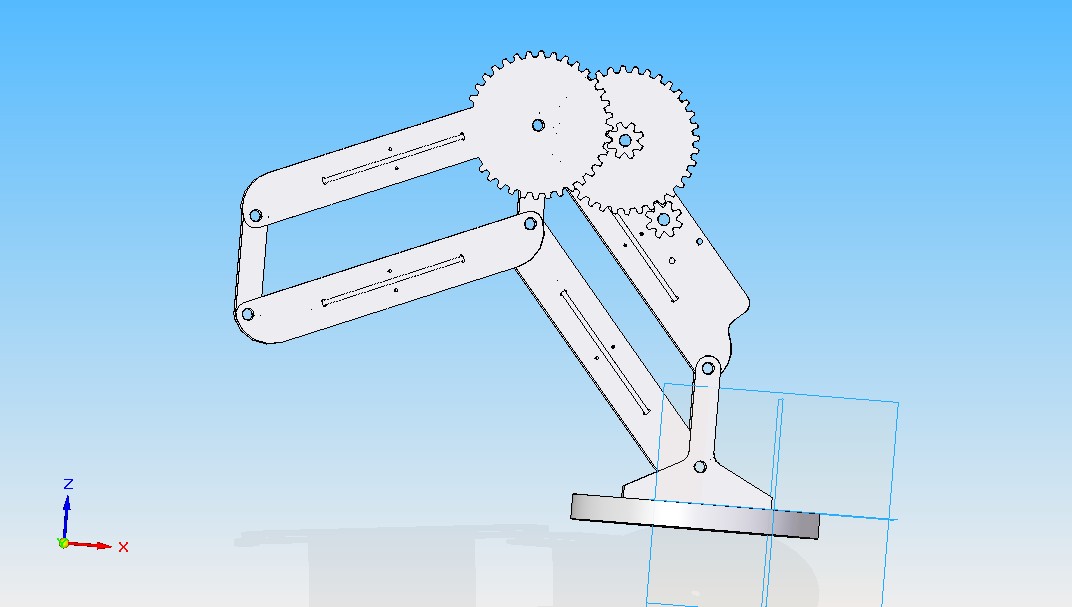
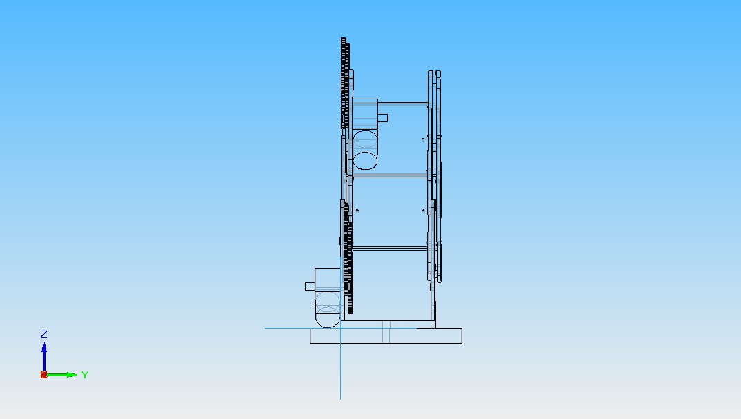
Here are some pictures of the new and improved robotic arm printer. I added two gears with 60: 8 ratios, so a total of 56.25 : 1. This is meant to be used with a 9v motor from
[robokitsworld.com]
that attaches to the inside and drives the small gear. 56.25 to 1 means that the rated torque for the motor goes up to 195.3 lb- in (at stall), and the rpm goes down to around 3.56 RPM. I will make an encoder wheel so that the microcontroller can read the position.
I am planning to mill the parts out for this as soon as I get my cnc working again. The motor coupler is stripped out.
Edited 1 time(s). Last edit at 03/14/2010 06:11PM by galaxyman7.
|
Re: Robotic arm printer March 14, 2010 09:42PM |
Registered: 15 years ago Posts: 59 |
|
Re: Robotic arm printer March 16, 2010 03:30AM |
Registered: 14 years ago Posts: 198 |
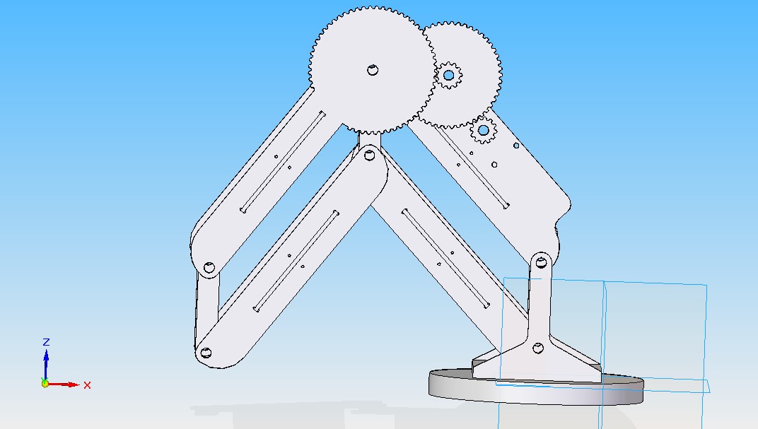
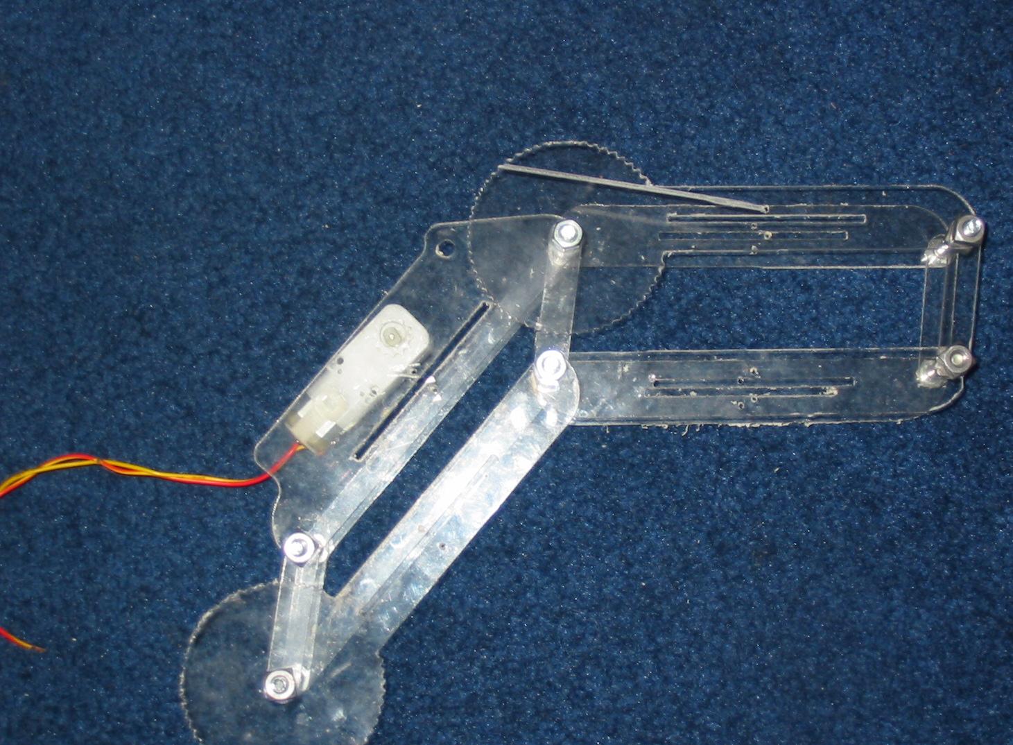
I just changed the total ratio to 30:1, so we could get more speed, plus I made the gear teeth smaller for higher accuracy. Now the RPM should be around 6.6 and the torque around 100 lb - in. Pictures attached.
|
Re: Robotic arm printer March 17, 2010 01:38PM |
Registered: 14 years ago Posts: 198 |
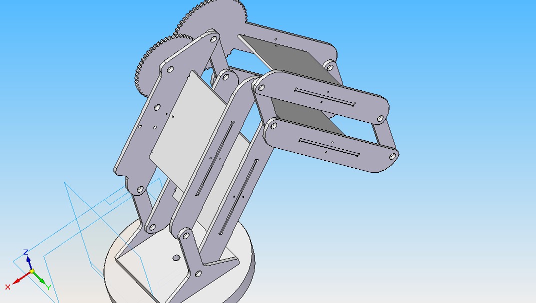
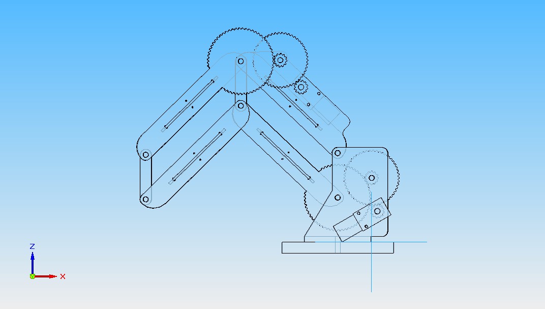
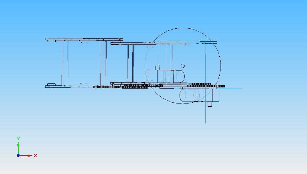
Added the drive system for the bottom link. Also added a few motors to the 3-d model. pictures attached
|
Re: Robotic arm printer March 17, 2010 08:27PM |
Registered: 14 years ago Posts: 198 |
Just saw this on the wiki page and thought I would link to it here. This is almost the exact same project I am working on.
[builders.reprap.org]
[builders.reprap.org]
|
Re: Robotic arm printer March 20, 2010 01:21PM |
Registered: 14 years ago Posts: 198 |
|
Re: Robotic arm printer March 24, 2010 03:41PM |
Registered: 14 years ago Posts: 198 |
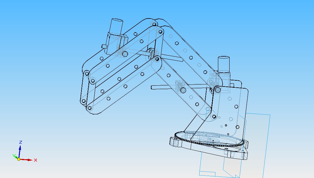
Ok, the design for the arm is pretty much done. For now it uses a 1/2 inch HDPE base, which could probably be cut down more. I think I will use two sheets of .125 plastic instead, and bolt it down to some plywood. If the arm needed to be portable, there would need to be a heavy base to keep it from falling over.
So, once I get some free time over spring break next week, I will probably get at least the mechanical part done. I have plenty of plastic, so that should be no problem. Next step, encoder and motor driver. I was thinking of using a black and white pinwheel type optical encoder.
So, once I get some free time over spring break next week, I will probably get at least the mechanical part done. I have plenty of plastic, so that should be no problem. Next step, encoder and motor driver. I was thinking of using a black and white pinwheel type optical encoder.
|
Re: Robotic arm printer March 25, 2010 03:56PM |
Registered: 14 years ago Posts: 105 |
[sourceforge.net]
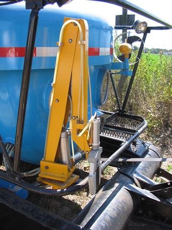
This image came from the the "Personal Subs" mailing list. The folded steel design mirrors my throughts on the way to approach the situation drawing from backhoes for inspiration.
In fact: toy excavators may be a good candidate for sourcing a ready built arm waiting for the attatchment of pnuematic cylinders.
The arm pictured uses pnuematic cylinders filled with vegetable oil is my understanding.
If I had to guess: I would say he gutted the hydraulic pump/resovoir/valve assembly from a log splitter and added a few more valves.
"hydraulic Spool valves"/"Hydraulic servo valves" are a good place to start.
The new "Robotnaut 2" from NASA seems to represent the state of the art.
Although pneumatic muscles seems to have a lot going for them as well.
Edited 1 time(s). Last edit at 03/25/2010 04:01PM by JohnnyCooper.
|
Re: Robotic arm printer March 25, 2010 07:39PM |
Registered: 14 years ago Posts: 198 |
|
Re: Robotic arm printer March 28, 2010 03:03PM |
Registered: 14 years ago Posts: 198 |
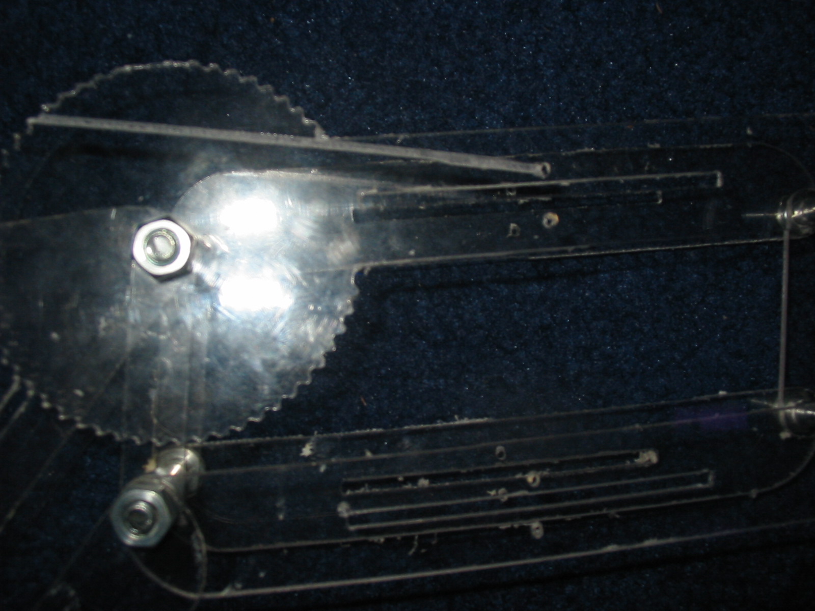
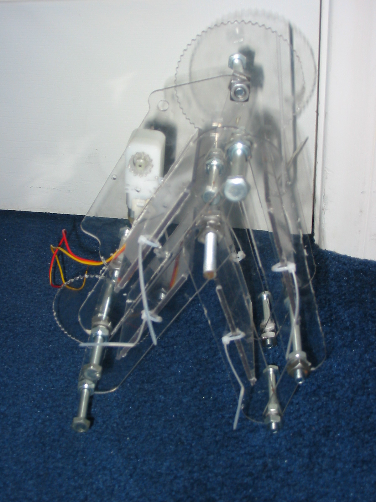
New pics for the robotic arm! I just milled these out from some polycarbonate. It was kind of a pain to hold down the smaller pieces when milling, but overall they came out well. My computer also tried to go into standby during the milling process, which totally screwed it up, but luckily it didn't affect anything.
I will mill out the base for it and the cross slats in a couple days.
I will mill out the base for it and the cross slats in a couple days.
|
Re: Robotic arm printer March 30, 2010 02:15AM |
Registered: 14 years ago Posts: 198 |
I just put the STL files on thingiverse.
[www.thingiverse.com]
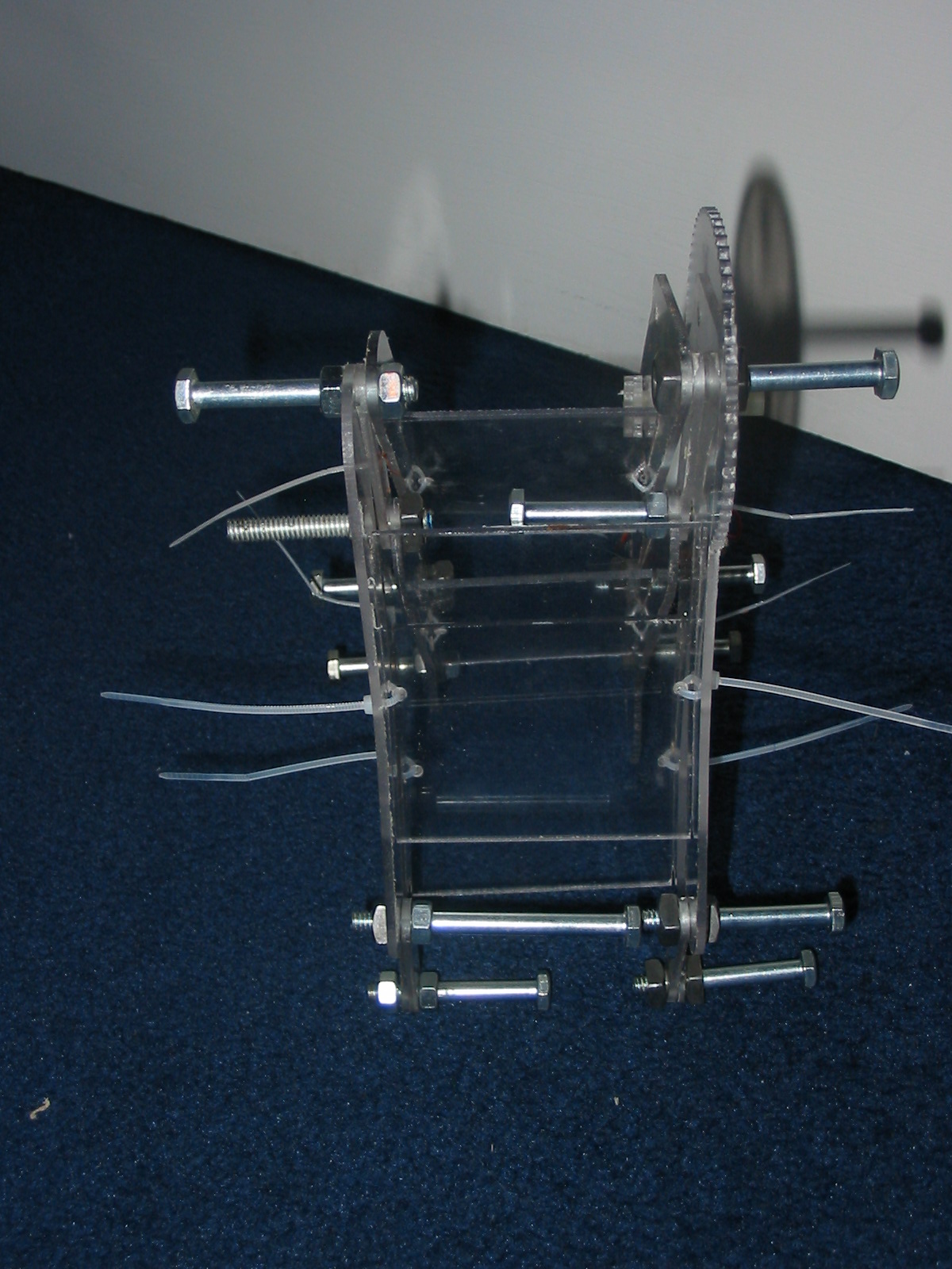
Also, I just finished some more of the robotic arm. Pics attached.
[www.thingiverse.com]
Also, I just finished some more of the robotic arm. Pics attached.
|
Re: Robotic arm printer March 30, 2010 03:34AM |
Registered: 14 years ago Posts: 105 |
|
Re: Robotic arm printer March 30, 2010 01:39PM |
Admin Registered: 17 years ago Posts: 1,791 |
galaxyman7, I forget, are you doing this up on a wiki page as well?
You've got a mill? Going to bolt an extruder on it?
-Sebastien, RepRap.org library gnome.
Remember, you're all RepRap developers (once you've joined the super-secret developer mailing list), and the wiki, RepRap.org, [reprap.org] is for everyone and everything!
You've got a mill? Going to bolt an extruder on it?
-Sebastien, RepRap.org library gnome.
Remember, you're all RepRap developers (once you've joined the super-secret developer mailing list), and the wiki, RepRap.org, [reprap.org] is for everyone and everything!
|
Re: Robotic arm printer March 30, 2010 02:03PM |
Registered: 14 years ago Posts: 198 |
The machine is polycarbonate.
I am not doing it on the wiki. How do I find the page for it, and how do I edit it?
By the way, I do have a mill, and I was looking to put an extruder on it. First I have to get this project done. If we can get the software sorted out for this, then I will probably use the robotic arm as a printer instead. The great thing about the robotic arm is that the only outside source of parts is for bolts and nuts. And even those can probably be elminated. This reprap only needs around 19 cubic inches of material (not including the base, which is made from mdf). And it can make itself in one print, since it can print all the way around itself.
|
Re: Robotic arm printer March 30, 2010 03:20PM |
Registered: 14 years ago Posts: 278 |
The physical hardware is looking great. Good job.
How were you planning on feeding the plastic to the extruder? Bowden extruder?
I suspect you'll find, as I did, that software for these kinds of machines become the hardest challenge. In my opinion, this is a very good thing, because:
- It is just as easy to give someone a copy of complicated software as it is to give them a copy of simple software.
- It is much harder to give someone a copy of a complicated machine compared to giving them a simple machine.
In your case, you're printed part volume is about 1/3 the mendal print volume, so you could theoretically replicate it 3x faster. RepolaRap would require more MDF for the repstrap and full reprapped copy, and a reprapped RepolaRap would require a bit more print volume because of the large gears I envision to drive the platforms vs. the belt drive the repstrap uses.
As a side note, looking at the gears on your arms, it seems to me some accuracy problems may exist ... a small error in the gear teeth spacing, gear slip (the gear teeth look awfully shallow..), or backlash looks to be amplified 5-10x by the time the motion translates to the business end of the extruder. Had you thought about possible plan B's to run your motion, for example, using a set of cables and 'crane' style configuration to give greater leverage and greater accuracy? Not sure that would help, either, though. Prototyping your current design would probably show any problems if they exist...
|
Re: Robotic arm printer March 30, 2010 08:21PM |
Registered: 14 years ago Posts: 198 |
Actually, because of the weight of the extruder, there should be no backlash since the gears will always be in contact on one side of the tooth.
The only axis with backlash is the bottom large gear, which is not always in contact with one side. The way to measure backlash is to have an electrical contact home switch, so that when the arm hits the switch, and then reverses, it will run until the electrical contact is broken. It will store this value for backlash and then either compensate on the chip itself or output the backlash value so it can entered in Mach3 or EMC2.
So the real problem is maintaining accuracy of the gears from generation to generation. However, if the optical encoder is placed on the large gear that is attached to the arm, the gear tooth accuracy will not matter, since the microcontroller just moves the motor until it sees another black line. What happens in between doesn't matter very much, assuming the lines are very close together. So this way, the accuracy is maintained from generation to generation.
|
Re: Robotic arm printer March 30, 2010 10:35PM |
Registered: 14 years ago Posts: 198 |
|
Re: Robotic arm printer March 30, 2010 11:45PM |
Registered: 14 years ago Posts: 278 |
Very cool. Some of the images are a tad blurry. I like how compact the whole thing is.
galaxyman7 Wrote:
> However, if
> the optical encoder is placed on the large gear
> that is attached to the arm, the gear tooth
> accuracy will not matter, since the
> microcontroller just moves the motor until it sees
> another black line. What happens in between
> doesn't matter very much, assuming the lines are
> very close together. So this way, the accuracy is
> maintained from generation to generation.
Yes.. encoders will help a great deal. I also may need use encoders; when I was looking, optical encoders did not seem to go to the resolution that appear to be necessary here. For .1 mm degree accuracy at the head, you need to have for the configuration you've done here - rough number of steps per rotation to get .1mm resolution appear to be greater than 10000 encoder pulses per revolution.. about 1000 lines per inch for a 5cm radius gear on a 20cm radius arm. Sebastion found some encoders that get up to about 200 lines per inch, which would give you .5mm accuracy -- may be enough for a rough copy.. but printing gears with this kind seem a bit of a challenge. What were the numbers you were coming up with? Did I miss the mark by making assumptions -- perhaps you found an encoder that has much higher resolution / steps per rev?
The optical encoders I may use on RepolaRap use a wheel about 12cm in radius, with 30-40 lines per cm (~100 per inch), resulting in 3000-4000 pulses per revolution, and giving me about .03mm accuracy worst case, and 0.1-0.2mm accuracy average case. If I used the 200 lines per inch encoders, I would reduce all those numbers in half, getting the needed .1mm resolution, but I think to use such a system with the arm configuration you've designed, you would need a much larger gear or at least wheel for the encoder portion..?
Edited 1 time(s). Last edit at 03/30/2010 11:46PM by BeagleFury.
|
Re: Robotic arm printer March 31, 2010 02:25AM |
Registered: 14 years ago Posts: 198 |
Actually the way they do it is by having multiple strips of encoder lines offset from each other, with multiple sensors. This way you do not need 1000 lines per inch.
Anyways, I was also thinking that a simple potentiometer could be used for the arm joint motors, since they only rotate about 90 degrees maximum. An RC time circuit or something better could read the resistance and get the angle from that. For the base motor, the gear is 12.7 cm, so an optical encoder will work fine.
Anyways, I was also thinking that a simple potentiometer could be used for the arm joint motors, since they only rotate about 90 degrees maximum. An RC time circuit or something better could read the resistance and get the angle from that. For the base motor, the gear is 12.7 cm, so an optical encoder will work fine.
|
Re: Robotic arm printer March 31, 2010 09:24AM |
Registered: 14 years ago Posts: 278 |
galaxyman7 Wrote:
> Anyways, I was also thinking that a simple
> potentiometer could be used for the arm joint
> motors, since they only rotate about 90 degrees
> maximum. An RC time circuit or something better
> could read the resistance and get the angle from
> that. For the base motor, the gear is 12.7 cm, so
> an optical encoder will work fine.
I wonder whether you would find a the repeatibility for a potentiometer that could approach the accuracy needed, I.E, for a given position, I would expect a 0.1% - 5% error in readings for that position (Even 0.1% error translates to about ~1mm position error, given the lever arm). Wirewound pots would probably give the highest accuracy.. but those can be a tad expensive; last I looked, they were at the $25+ each range.
Certainly, give it a try though -- a potentiometer encoder would be extremely easy to build and install vs. an optical encoder.
|
Re: Robotic arm printer March 31, 2010 12:24PM |
Registered: 14 years ago Posts: 198 |
Good point. I don't think potentiometers will be that accurate.
Back to optical encoders-
An accuracy of .1 mm can be attained using multiple sensors that are offset from eachother (quadrature encoders), but this would require many pins on the microcontroller. The only other way is to convert this parallel data to serial, giving you binary output to the microcontroller. This method basically divides the amount of lines per inch you need by the amount of rows you have. So 5 rows would give you 200 lines per inch instead of 1000.
However, I think putting the encoder directly on the motor is probably much easier, since the ratio is 30:1. This means I only need 100 lines per inch on the encoder to get .1 mm accuracy. I know there will be a problem with backlash and non uniform rotation, but hopefully this can be compensated for in program.
|
Re: Robotic arm printer March 31, 2010 01:36PM |
Registered: 14 years ago Posts: 278 |
galaxyman7 Wrote:
> An accuracy of .1 mm can be attained using
> multiple sensors that are offset from eachother
> (quadrature encoders), but this would require many
> pins on the microcontroller. The only other way is
> to convert this parallel data to serial, giving
> you binary output to the microcontroller. This
> method basically divides the amount of lines per
> inch you need by the amount of rows you have. So 5
> rows would give you 200 lines per inch instead of
> 1000.
You'll run into variations unless you can both fine tune the exact positions of each encoder (+- 0.1mm) and/or align the encoder wheel. On the positive, you should be able to overcompensate, by adding more encoders than necessary and using signal analysis to tune the machine without fine tune adjustment. I believe this is the technique that the AEDR optical encoder module I looked at uses, to get 212 lines per inch optical resolution.
Also, curious.. given the structure of your bot, you might find better accuracy from a transmissive encoder -- I suspect many printers probably have the level of resolution you'd need (The encoder disks tend to have a "grey smudge" appearance because of the high LPI encoding they use..)
The other thought is rotary magnetic encoders -- though, I think I've only seen them go up to 4000 pulses per revolution.
|
Re: Robotic arm printer March 31, 2010 02:36PM |
Admin Registered: 16 years ago Posts: 13,884 |
... i was collecting all parts for a delta-robot but delayed this after finishing the diodelaser-modules.
With the 4Nm-berger-lahr-motors and controllers i have a stepping resolution of 10000 steps per turn (one has a 5:1 planetary gearbox, so 50000 steps) and i have some optical ROD-encoders with 9000 lines, so more than enough resolution.
Maybe instead of a delta it would be more interesting to build a polar or double-scara?
But this has to wait until summer ...
Viktor
--------
Aufruf zum Projekt "Müll-freie Meere" - [reprap.org] -- Deutsche Facebook-Gruppe - [www.facebook.com]
Call for the project "garbage-free seas" - [reprap.org]
|
Re: Robotic arm printer March 31, 2010 04:15PM |
Registered: 14 years ago Posts: 198 |
Yes, transmissive is probably better. I found this opto interrupt transistor on digikey> [www.semicon.panasonic.co.jp]
It only costs $1.
It says that it can go up to .05 mm position detection, which translates to .2 mm at the end of the arm. I think this is good enough for making pretty much anything. The only problem is getting a disk that would work with it.
Do you know any sources of encoder disks?
It only costs $1.
It says that it can go up to .05 mm position detection, which translates to .2 mm at the end of the arm. I think this is good enough for making pretty much anything. The only problem is getting a disk that would work with it.
Do you know any sources of encoder disks?
|
Re: Robotic arm printer March 31, 2010 04:40PM |
Registered: 14 years ago Posts: 198 |
on a side note, I found a free open source usb to parallel port converter made for CNC. It uses his own free software, which looks good enough for me.
[www.cncdudez.co.uk]
[www.cncdudez.co.uk]
|
Re: Robotic arm printer April 02, 2010 02:36AM |
Registered: 14 years ago Posts: 198 |
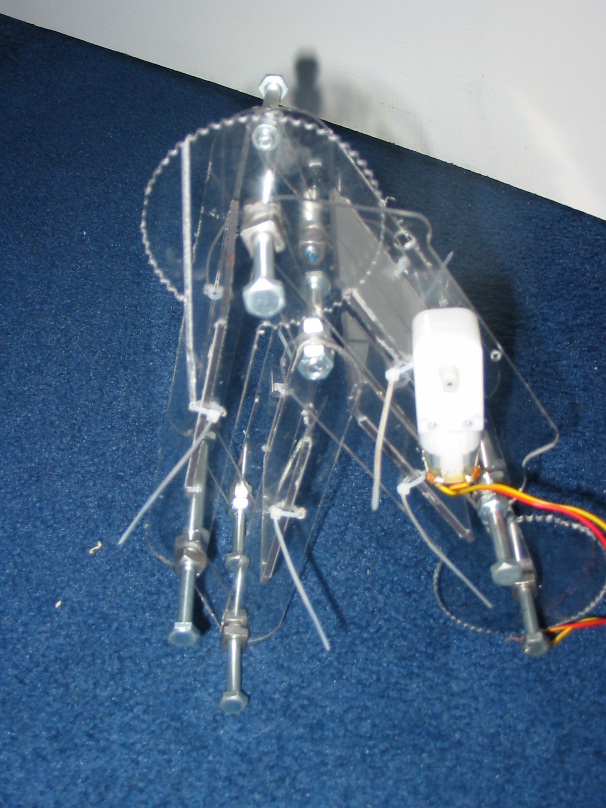
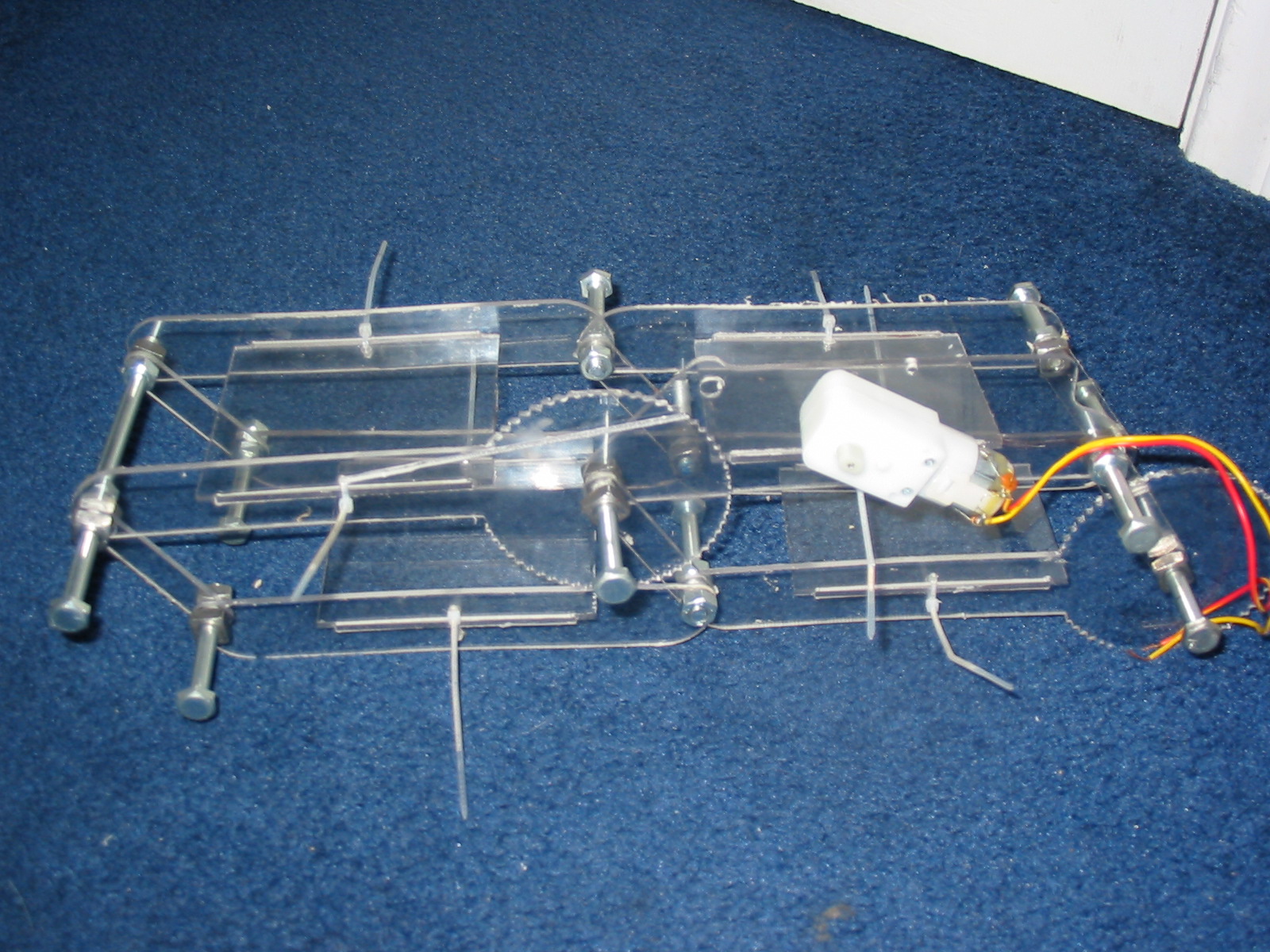
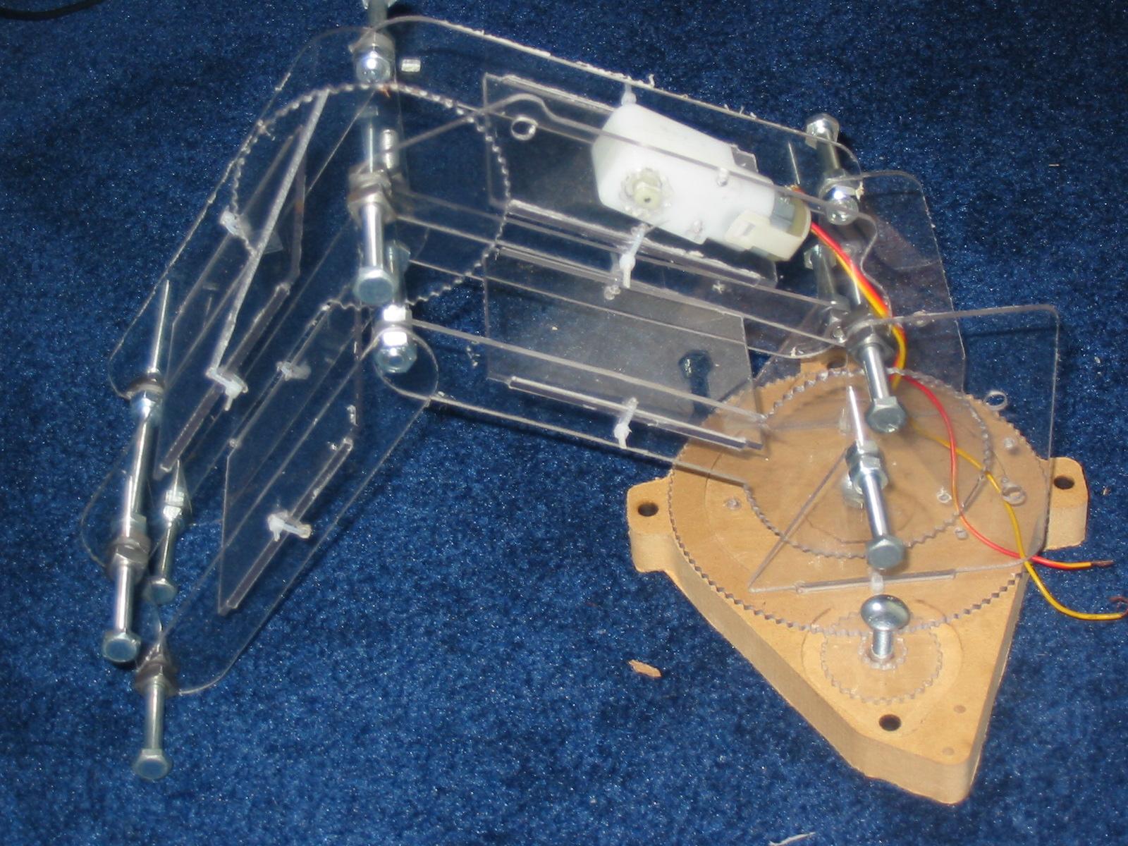
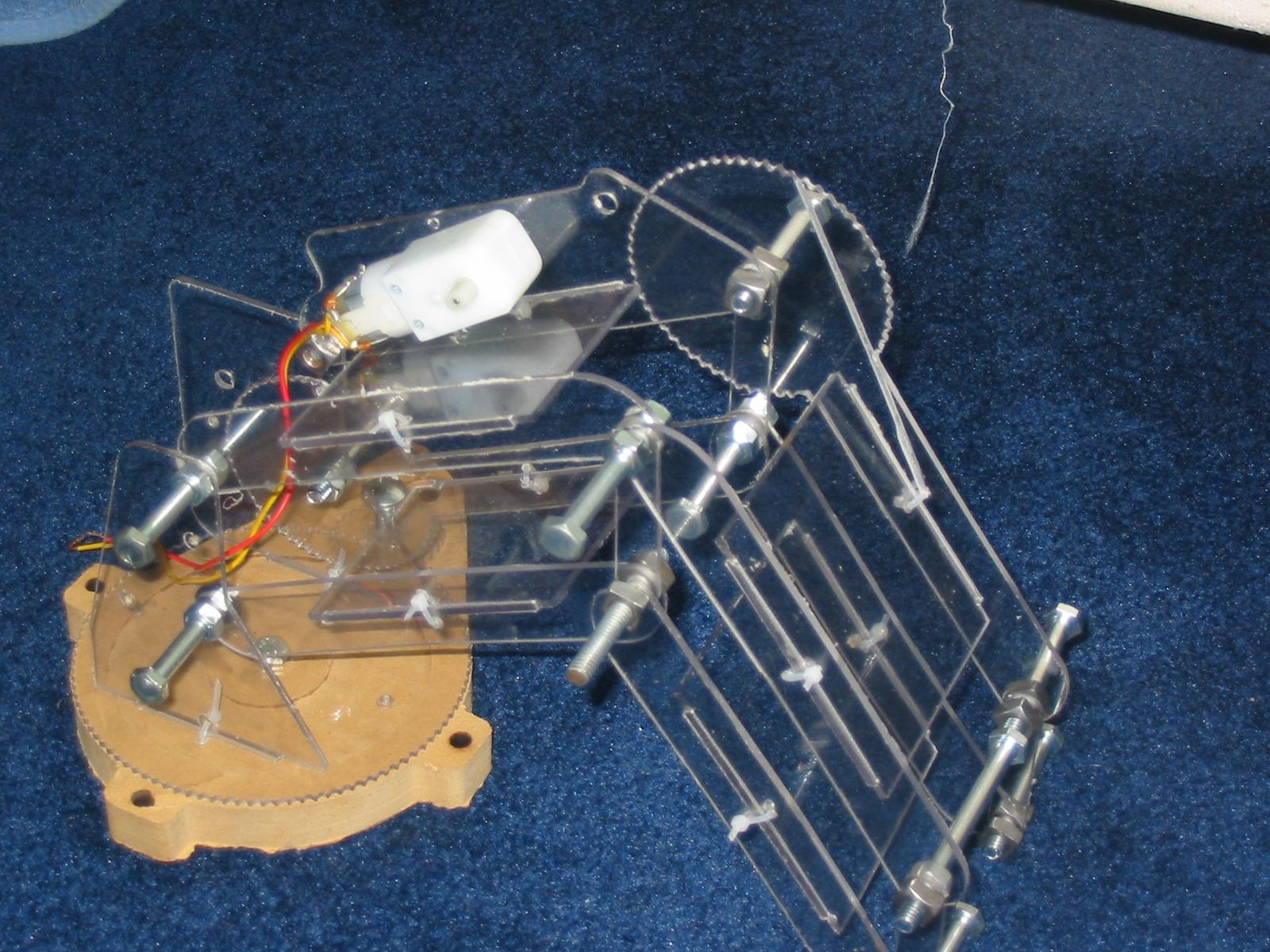
Hey, I have thought about the gear design, and I have decided it is too much trouble both to make it work and to maintain accuracy. Therefore I have changed the design to something much simpler, a threaded rod driven arm. The way it works is this:
There is a pivoting holder for the nut on one parts of the frame
There is a pivoting holder for the motor on another part
They are connected by threaded rod, when the motor turns, the two points get closer together or move apart.
When the points change distance, the arm rotates.
This seems much simpler than all the gears and much more accurate.
The last gear to get rid of is the base. I need to find an easy way to drive the base using threaded rod.
A picture of the new experimental design is attached.
|
Re: Robotic arm printer April 02, 2010 08:05AM |
Registered: 14 years ago Posts: 278 |
galaxyman7 Wrote:
-------------------------------------------------------
> Hey, I have thought about the gear design, and I
> have decided it is too much trouble both to make
> it work and to maintain accuracy. Therefore I have
> changed the design to something much simpler, a
> threaded rod driven arm. The way it works is
> this:
> There is a pivoting holder for the nut on one
> parts of the frame
> There is a pivoting holder for the motor on
> another part
> They are connected by threaded rod, when the motor
> turns, the two points get closer together or move
> apart.
> When the points change distance, the arm rotates.
> This seems much simpler than all the gears and
> much more accurate.
>
> The last gear to get rid of is the base. I need to
> find an easy way to drive the base using threaded
> rod.
>
> A picture of the new experimental design is
> attached.
I think the gear on the base, or a belt drive, actually will keep your design simple and easy to build. If needed, you might consider using a larger 'gear' as per RepolaRap, and an anchored belt drive -- a toothed belt (US$8.00) + pully ($8.00) + stepper ($20.00) will give you a drive mechanism with no backlash, near 100% repeatability, and accuracy as high as you like simply by adjusting the gear ratio between the motor and the wheel (making the base wheel larger, for example.)
And, for your design, I'd suggest moving the 'elbow' motor to the other side, and move it closer to the base to reduce the effect of gravity inducing torque to topple your machine in different configurations (The extruder itself will also contribute to this..) The formula for that motor position would still be a relatively simple calculation.
Edited 2 time(s). Last edit at 04/02/2010 08:30AM by BeagleFury.
|
Re: Robotic arm printer April 02, 2010 07:28PM |
Registered: 14 years ago Posts: 198 |
I am still using the geared hobby motors, but the encoder wheel will only need 100 steps around the wheel,giving it .005" accuracy (20 turns per inch) . The motors weigh barely anything (maybe 3 ounces?), so its not a problem. The whole machine will be bolted down anyways.
The reason why I don't move the motor is because the two threaded rods would collide with other parts. The way I have it, the rods don't interfere with eachother or other parts. Maybe later I will move the motors around some more to optimize the design, but I really just want to get one working.
About the gear on the base, how will I get a gear that size accurately made? I thought you said that if I made a gear, it would create inaccuracy.
Also, I still want to do away with stepper motors, so that's why I want to change to threaded rod, which creates much more accuracy. If you come up with a design for the base that is cheap and can be used with the hobby motors, tell me.
|
Re: Robotic arm printer April 02, 2010 09:23PM |
Registered: 14 years ago Posts: 278 |
galaxyman7 Wrote:
> About the gear on the base, how will I get a gear
> that size accurately made? I thought you said that
> if I made a gear, it would create inaccuracy.
> Also, I still want to do away with stepper motors,
> so that's why I want to change to threaded rod,
> which creates much more accuracy. If you come up
> with a design for the base that is cheap and can
> be used with the hobby motors, tell me.
I see. I can't think of any easy to assemble platform drive from hobby motors. You're familiar with the angular momentum, print speed, and gearhead/backlash problems you'll face? What prices are you targeting for the servos? I found that by the time you've added encoder sensors, electronics, and gears, you might as well have purchased a stepper motor at the same price..
|
Re: Robotic arm printer April 02, 2010 10:39PM |
Registered: 14 years ago Posts: 198 |
It isn't going to use any servos, just the hobby motors from here>>
[robokitsworld.com]
They cost 4.22 each.
For the encoder, I will just use paper with black stripes printed onto it, an LED and a phototransistor. So for each motor and encoder, it will be around $5.
As for the angular momentum, that is also a reason why I want to use threaded rod, since it cannot be backdriven. I know there will be some oscillation if the arm is stopped suddenly, so the ramping needs to be calibrated so that it will not oscillate.
Print speed- I am hoping this will be fairly high, but because of angular momentum, it could be limited somewhat. I am aiming for around 20 fpm. The important thing is that the machine is very cheap, but accurate. If you want to make something fast, build more of the machines, maybe even link them together in parallel. This way someone who wants to build a machine just as a hobby doesn't need much speed, and so he doesn't need to spend much money.
Backlash- In the arm the backlash will be zero, since the weight of the extruder will force the threads against one side all the time. On the base, I was hoping to use some kind of tensioning device, it depends on the design.
gearhead problems- The motors do have gears in them, but I think they will cause very little error, since the encoder is connected after the gears rather than before.

Sorry, only registered users may post in this forum.