Polar topologies
Posted by BeagleFury
|
Polar topologies March 15, 2010 08:48AM |
Registered: 14 years ago Posts: 278 |
Wanted to throw out a thread that discusses the different topologies for polar bots. My discussions below assume that the printhead itself includes the same degrees of freedom as a corresponding cartesion bot (I.E, extruder rate and extruder temperature.)
There are 5 total degrees of freedom for the physical orientation of a generic print head. One set of variables (cartesion) for describing this are:
X position
Y position
Z position
rotation about Z.
incline angle from Z.
Typically, a reprap wants a fixed Z incline (the extruder orientation 'downwards', it does not change), and does not care about rotation about Z (it is free to change without affecting the realized position), so usually, only 3 degrees of freedom for physical location/orientation need to be used on a reprap or repstrap. It should also be noted that the 5 (or 3) degrees of freedom may differ from that above, but can be transformed to the form above; this is the basis for using a set of polar degrees of freedom.
The 3 degrees of freedom can produce linear motion, or angular motion. Some of the topologies proposed include:
- Dual Disk Cylindrical (One possible RepOlaRap configuration)
- Rotating Two Link Arm (galaxyman7 is working on something like this)
- Dual Disk with polar Z (Another possible RepOlaRap configuration)
* This would be the standard X+Y RepOlaRap, with something like a sarrus linkage for Z motion, where the motor drives the angle on one of the sarrus links.
- Delta Configuration
- Hybrid linear where the drive changes the linear position, but motion is described by nonlinear linkages to the linear position.
Are there any others that people are actively working on?
Edited 1 time(s). Last edit at 03/15/2010 10:24AM by BeagleFury.
|
Re: Polar topologies October 21, 2010 04:15PM |
Registered: 13 years ago Posts: 20 |
Is it possible to build a 3D CNC extruder with only 2 motors?
You have 3 dimensions, so it seems obvious that you need 3 positioning motors (not counting the extruder motor).
So where am I going wrong in the following napkin-sketch?
I'm looking at [http://staff.bath.ac.uk/ensab/replicator/Downloads/Wargers/wargers.html Hans Wargers turntable prototype].
* the "z" motor turns the circular build platform around a fixed threaded rod at its center,
* the "r" motor moves the printhead along a fixed radial line (radius) from close to the threaded rod in the center to close to the outer perimeter of the build platform.
So far, it looks just like like the Hans Wargers prototype: a cylindrical topology.
But the allegedly "clever" bit that lets us get away with only 2 motors is:
* While printing out one layer, the "z" motor turns the build platform back and forth relatively small angles.
* Once a layer is done, the same "z" motor spins the build platform a complete 360 degrees in the "down" direction. As the nut welded to the build platform turns on the fixed threaded rod, that lowers the build platform one thread of the central threaded rod.. Hopefully 1 thread is precisely 1 layer of plastic thick. Perhaps some print heads / plastics need thicker layers, so the "z" motor spins 2 turns -- 720 degrees -- between layers.
* Then the machine prints the next layer, moving back and forth relatively small angles.
There are certain points this topology can't reach -- points "between" layers.
Do we really need to move the nose of the print head to any of those points?
|
Re: Polar topologies November 29, 2010 02:30AM |
Registered: 14 years ago Posts: 198 |
That is a really cool idea! The print would be slightly angled though, since when the arm moves across the surface, it will also being going up slightly. This can be compensated for with a slightly angled print bed. Also, getting the motor to rotate that precisely would require a stepper motor with very small increments, or a servo with very fine positioning. It might be worth it to use two cheaper motors rather than one very precise motor. The concept is really cool though, and if it could be adapted to a less precise motor, it could cut costs dramatically.
|
Re: Polar topologies November 29, 2010 07:44AM |
Registered: 15 years ago Posts: 376 |
Sounds like quite a neat idea rotating the platform by 1 rev to act as the z axis, but a thread with a pitch of say 0.5mm would probably be very small in diameter. For example a standard Metric M3 has a pitch of 0.5. You can of course manufacture a thread with any pitch you want, but this just adds complexity.
A simpler method than an angled bed would be to have the bed rotating around the centre as you have suggested but keep the bed horizontal, the XY robot prints the layer as normal, then moves off the print area and locates behind a vertical post sticking up from the bed (called a "dog" in engineering.). The XY robot then moves in a circular arc around the table and using the dog winds the table up or down. The XY robot then moves back to the print area to begin the next layer. This eliminates any compound angle calculations and simplifies the design somewhat. The XY robot could also operate a lever which engages in the edge of the table to lock the angular position when you are printing the layers.
A further advantage would be that you wouldn't require a fine pitch thread. The XY robot doesn't have to rotate the table a full 360 degrees, but only a small angle to raise the bed a portion of the pitch. You just have to accomodate this new angle in the print coordinates of the next layer.
The disadvantage I can see is that the print nozzle would have to be installed in a vertical cylinder as the outer surface would be needed to operate the "dog".
Edited 1 time(s). Last edit at 11/29/2010 07:46AM by martinprice2004.
|
Re: Polar topologies February 12, 2011 01:58PM |
Registered: 13 years ago Posts: 3 |
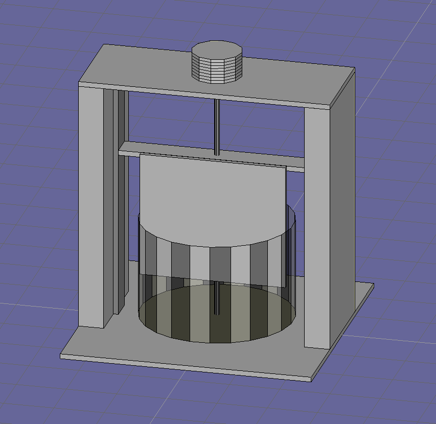
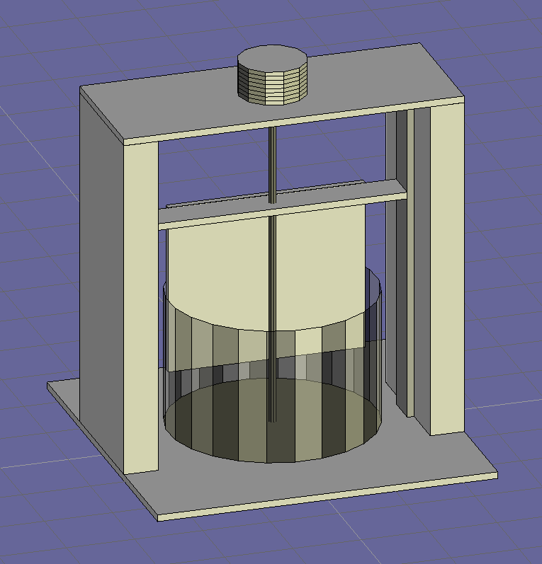
I've been tinkering with a similar printer concept as described earlier in this thread. It is a powder based polar printer.
The basic idea is that a cylinder (a tin can) is attached to a threaded rod running down the center of the device. A motor is attached to this threaded rod as seen on the top. Additionally there is a sort of platform attached to the threaded rod by means of a threaded nut. The platform is attached to sliders on either side of the printer so that it moves up and down as the threaded rod and cylinder rotate.
A plate is attached to the platform. What this plate does is allow a pile of material (ground wax - not shown) on one side of the plate to be pushed under the gap that the plate makes with the cylinder as it rises. This creates a continuous smooth layer of powered material that can then be selectively fused.
As the smoothed layer of material passes under the plate a series of heating elements (not shown in the drawing) are activated to selectively fuse the material to underlying layers. Right now this is a problem for me as the ground wax sometimes wants to stick to the heating elements. A no-contact heat source will probably be required.
I've attached a few renderings of the printer from the front and back sides of the printer as well as a short animated clip demonstrating how it operates. It's a very rough drawing so please forgive me. I'll upload a few pictures of the actual built version of this if anyone is interested. Please feel free to ask for any clarifications.
Sorry, only registered users may post in this forum.