started designing a new mostly-plastic reprap SCARA with fishing line motion transmission and unorthodox winch for Z
Posted by realthor
|
started designing a new mostly-plastic reprap SCARA with fishing line motion transmission and unorthodox winch for Z May 25, 2015 07:51AM |
Registered: 9 years ago Posts: 1,035 |
Hello guys. I am designing a new RepRap style single-Arm SCARA printer that has all its motion transmitted via fishing line and it's mostly plastic constructed.
The whole project idea came from previous great work done with Wally and Morgan but my engineer within wanted to take this further with the rep-rappiness. This thread is to document my WIP and get advice from the true engineers and builders roaming this forum. I have started this on ConceptForge but I will continue here to potentially get more coverage and advise as I move along half blindfolded by my lack of experience.
A little bit about myself: I have a background in engineering but worked in IT administration for my whole life, so my engineering skills have long faded away. I am a big fan of the rep-rap idea as it fits perfectly among the non-patented, shared knowledge, self-reliant, produced as needed, etc concepts that I adhere to.
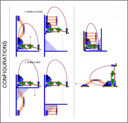
I have named my 3d printing bot Lander because of it's goals. Similar to the landers we've sent to explore the Moon and Mars, this bot should be able to work in different conditions and self-replicate. It will mostly work on vertical structures like walls but should as well work in a hanging position from under a table for example or sit on the desk or even roll on the floor while horizontally printing. These are all ambitious goals indeed but I will be happy to achieve the wall configuration with success.
The goals list goes like this:
This is an initial sketch showing some configurations:
With the current design the bot is composed of:
1) 1-Arm SCARA that uses two stepper motors to rotate the shoulder and elbow using fishing line spooled on larger diameter drums to ensure enough mechanical advantage and triangulation-free motion transmission;
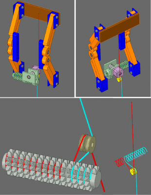
2) A winching system for Z movement that is based on an unorthodox (and 3D printed) "threaded spur gear", like presented below.
3) Supporting plastic components that hold it together
SCARA:
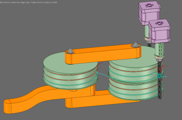
The SCARA works like this: the stepper turns an M8 bolt that has Spectra fishing line coiled around the threading in a number of loops. Because the bolt is fixed axially, as it turns, the coils will travel up and down depending on the direction of rotation. The motion is transmitted to the larger drums which have themselves coils that complete the system. These coils on the drums must travel up and down the drums in the same way if "triangulation" errors are to be avoided. Therefore they have grooves that are similar to the threads on the bolt but calculated in such a way as to keep the line between the bolt and the drum parallel at all times. This is also why I ended up with such tall drums, as the loops on them need to travel the same distance on Z as the coils on the bolt are.
Note: an alternative design (extending motor couplers) has been discussed in "Ideas for next Wally" thread on ConceptForge. I might revert to that at some point, for now "less moving parts" has been an unofficial goal.
Because a picture is worth 1000words, here's a picture of the SCARA:
Z-WINCH:
The Z movement accuracy will be ensured by two mechanisms: one is a Double Parallelogram system that will make use of the Double Lamina Compliant Joint (DCLJ) to ensure perfectly vertical movement and the other one is a Winch system in which a stepper motor engages, via a worm, the winch drum that spools the fishing line. To avoid "triangulation", in this specific case, the fishing line is kept in a static vertical position and the drum moves to accommodate new coils. This is done via an unorthodox threaded spur gear combo that gets rotated by the worm and travels through some nuts.
Again, a picture is worth 1000words:
FRAME:
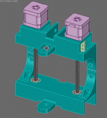
Instead of separate mounts for the steppers (like Wally) and a central piece to clamp the SCARA arms I have designed two (quite similar) cases, an upper one that holds all three steppers and the Z-motor-worm-spool mechanism and a bottom one that ensures the "below" support for the SCARA and "catches" the bolts' ends to prevent the bolts bending and wobbling. It can also hold a laptop-style PSU within the inner shell.
The Double Parallelogram has its own brackets as I plan to be able to detach it and used it to raise the platform while the bot is bolted to a wall. This is the Mobile Platform/Bed configuration showed in the first presentation image.
The Frame is still open to simplifying and the whole bot's looks would benefit from a better overall "presentation" design but I am quite ok with this form until all the functional aspects of the printer would have been ironed out.
WORKING AREA:
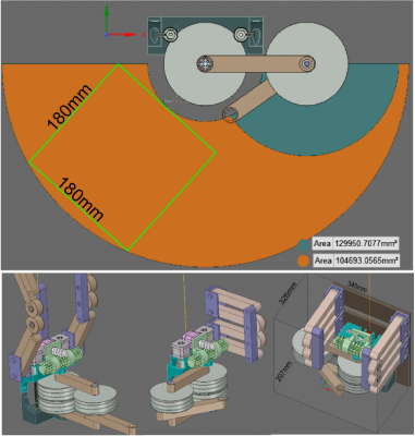
The working area that this bot is capable of is quite large compared to its dimensions. Below you have a hint at what it might look like:
I haven't yet figured out a way to tell the software what the working area shape is. I only know that squares and (maybe) parallelograms are supported. Looking at the working area above, the longest parallelogram that fits within the boundaries is 3.5times the length of the bot's arms, which are now 150mm between the centers of the end holes.
To Do List:
Besides ironing out all the issues with the design as is (which are a lot), I still have to:
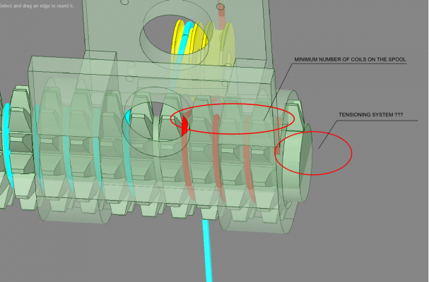
a) decide on a tensioning system for the fishing line (tensioning has been offloaded from the drums and can be done somewhere on the backboard of the bot)
b) have endstops somewhere and implement that in software (will be using Mogan's firmware, as it supports the movement of this bot if I constrain it to one side only)
c) will use a Delta-style hot-end with a bowden extruder placed somewhere at the back. What hot-end, what clamping solution, etc ... has to be decided
d) the CAD designs for each component have to be re-drawn (maybe by a better CAD person - I know CAD since 2 weeks ) and many details have to be still discussed:
- DLCJs: how many bearings per arm, how is the figure-8 string going to be secured and tensioned, etc;
- Z-system: threaded spur gear bolt, nuts and worm have to be accurately designed to generate printable STLs
- The electronics box (PSU+Arduino+Shield+LCD) can be designed in one piece fixed between the Double Parallelograms, which would confer a plus of rigidity to the system
- and many more
All above is officially opened for discussion. Please be constructive with your comments and patient with a noob in fabrication, CAD, 3d printing and mostly everything here
For many details that I didn't include here (why I have chosen certain solutions as opposed to others you could check ConceptForge ("Ideas for the next Wally" thread and " meet Lander, the multi-configuration 3d printer" thread)
Edited 3 time(s). Last edit at 05/25/2015 09:08AM by realthor.
The whole project idea came from previous great work done with Wally and Morgan but my engineer within wanted to take this further with the rep-rappiness. This thread is to document my WIP and get advice from the true engineers and builders roaming this forum. I have started this on ConceptForge but I will continue here to potentially get more coverage and advise as I move along half blindfolded by my lack of experience.
A little bit about myself: I have a background in engineering but worked in IT administration for my whole life, so my engineering skills have long faded away. I am a big fan of the rep-rap idea as it fits perfectly among the non-patented, shared knowledge, self-reliant, produced as needed, etc concepts that I adhere to.
I have named my 3d printing bot Lander because of it's goals. Similar to the landers we've sent to explore the Moon and Mars, this bot should be able to work in different conditions and self-replicate. It will mostly work on vertical structures like walls but should as well work in a hanging position from under a table for example or sit on the desk or even roll on the floor while horizontally printing. These are all ambitious goals indeed but I will be happy to achieve the wall configuration with success.
The goals list goes like this:
Quote
1) rep-rap to the bones: the current design has only bearings and bolts/washers as metal components, about everything else is plastc (and the fishing line, which is a vitamin but is plastic again)
2) no specialized or hard to find parts (linear rails, linear bearings, aluminum extrusions, etc)
3) low vitamin count, preferably more of the same kind than different ones (for emergency replacements/etc)
4) no timing belts, until we can print them, fishing line or other type of strong thread will be used instead
5) large printing area
6) multiple configurations and enhanced mobility: on the wall, on the floor, folded for transportation
7) as little metal as possible because of its energy intensive extraction and processing
8) precision over speed (complicated printed parts are allowed if achievable as they can be easily produced initially on another printer of similar precision)
9) can print larger versions of itself (should be easily scaled up by modifying a small number of components)
This is an initial sketch showing some configurations:
With the current design the bot is composed of:
1) 1-Arm SCARA that uses two stepper motors to rotate the shoulder and elbow using fishing line spooled on larger diameter drums to ensure enough mechanical advantage and triangulation-free motion transmission;
2) A winching system for Z movement that is based on an unorthodox (and 3D printed) "threaded spur gear", like presented below.
3) Supporting plastic components that hold it together
SCARA:
The SCARA works like this: the stepper turns an M8 bolt that has Spectra fishing line coiled around the threading in a number of loops. Because the bolt is fixed axially, as it turns, the coils will travel up and down depending on the direction of rotation. The motion is transmitted to the larger drums which have themselves coils that complete the system. These coils on the drums must travel up and down the drums in the same way if "triangulation" errors are to be avoided. Therefore they have grooves that are similar to the threads on the bolt but calculated in such a way as to keep the line between the bolt and the drum parallel at all times. This is also why I ended up with such tall drums, as the loops on them need to travel the same distance on Z as the coils on the bolt are.
Note: an alternative design (extending motor couplers) has been discussed in "Ideas for next Wally" thread on ConceptForge. I might revert to that at some point, for now "less moving parts" has been an unofficial goal.
Because a picture is worth 1000words, here's a picture of the SCARA:
Z-WINCH:
The Z movement accuracy will be ensured by two mechanisms: one is a Double Parallelogram system that will make use of the Double Lamina Compliant Joint (DCLJ) to ensure perfectly vertical movement and the other one is a Winch system in which a stepper motor engages, via a worm, the winch drum that spools the fishing line. To avoid "triangulation", in this specific case, the fishing line is kept in a static vertical position and the drum moves to accommodate new coils. This is done via an unorthodox threaded spur gear combo that gets rotated by the worm and travels through some nuts.
Again, a picture is worth 1000words:
FRAME:
Instead of separate mounts for the steppers (like Wally) and a central piece to clamp the SCARA arms I have designed two (quite similar) cases, an upper one that holds all three steppers and the Z-motor-worm-spool mechanism and a bottom one that ensures the "below" support for the SCARA and "catches" the bolts' ends to prevent the bolts bending and wobbling. It can also hold a laptop-style PSU within the inner shell.
The Double Parallelogram has its own brackets as I plan to be able to detach it and used it to raise the platform while the bot is bolted to a wall. This is the Mobile Platform/Bed configuration showed in the first presentation image.
The Frame is still open to simplifying and the whole bot's looks would benefit from a better overall "presentation" design but I am quite ok with this form until all the functional aspects of the printer would have been ironed out.
WORKING AREA:
The working area that this bot is capable of is quite large compared to its dimensions. Below you have a hint at what it might look like:
I haven't yet figured out a way to tell the software what the working area shape is. I only know that squares and (maybe) parallelograms are supported. Looking at the working area above, the longest parallelogram that fits within the boundaries is 3.5times the length of the bot's arms, which are now 150mm between the centers of the end holes.
To Do List:
Besides ironing out all the issues with the design as is (which are a lot), I still have to:
a) decide on a tensioning system for the fishing line (tensioning has been offloaded from the drums and can be done somewhere on the backboard of the bot)
b) have endstops somewhere and implement that in software (will be using Mogan's firmware, as it supports the movement of this bot if I constrain it to one side only)
c) will use a Delta-style hot-end with a bowden extruder placed somewhere at the back. What hot-end, what clamping solution, etc ... has to be decided
d) the CAD designs for each component have to be re-drawn (maybe by a better CAD person - I know CAD since 2 weeks ) and many details have to be still discussed:
- DLCJs: how many bearings per arm, how is the figure-8 string going to be secured and tensioned, etc;
- Z-system: threaded spur gear bolt, nuts and worm have to be accurately designed to generate printable STLs
- The electronics box (PSU+Arduino+Shield+LCD) can be designed in one piece fixed between the Double Parallelograms, which would confer a plus of rigidity to the system
- and many more

All above is officially opened for discussion. Please be constructive with your comments and patient with a noob in fabrication, CAD, 3d printing and mostly everything here

For many details that I didn't include here (why I have chosen certain solutions as opposed to others you could check ConceptForge ("Ideas for the next Wally" thread and " meet Lander, the multi-configuration 3d printer" thread)
Edited 3 time(s). Last edit at 05/25/2015 09:08AM by realthor.
|
Re: started designing a new mostly-plastic reprap SCARA with fishing line motion transmission and unorthodox winch for Z May 25, 2015 03:02PM |
Registered: 9 years ago Posts: 127 |
Hi,
that´s a very cool design, something I also was thinking about some time ago ! ;-)
First question: How do you pre-tension the fishing line and what diameter do you want to use? I think Spectra is made of Dyneema, so depending on line diameter the systems stiffness can be adjusted.
Second question: Already tried to run the Morgan-software as-is and move some motors with it? I had no success up to now.
Best regards,
Mike
|
Re: started designing a new mostly-plastic reprap SCARA with fishing line motion transmission and unorthodox winch for Z May 25, 2015 08:25PM |
Registered: 9 years ago Posts: 1,035 |
Tensioning is "a)" on my ToDo list  .
.
First of all I am not sure that having two separate loops to rotate to each side is such a good idea as I will have to tension each loop independently. This brings the issue of applying the exact same tension on each loop. Then I have some doubts that I can actually tension the wire behind the bolt. The mechanism of rotation transmission from bolt to drum is from empty bolt ( 1 coil left) and full drum to empty drum and full bolt. The same goes for the other half of the loop. This should rotate the drum 180deg to each side.
This means that if I am tensioning at any side I am actually only tensioning the free wire, while the coiled wire on the bolt or on the drum will only tension maybe one coil, maybe one and a half, while the other coils aren't affected. Doing a unwinding-winding cycle would distribute the tension in the whole loop but I am afraid of not over-stressing the free wire while initially tensioning it.
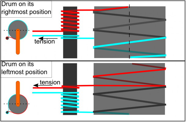
I am pretty tired but I think the following sketch should be fairly correct:
If the tensioning system behind the bolt is to have any success then the tensioning must be done when there is one coil left on the bolt. This is a situation when applying some tension to that wire will be enough for it to slip a bit on the bolt. Then the process should be repeated so that the other loop is brought to 1 coil left on the bolt and then tension is applied. This brings me to imagine a routine of turning the steppers enough steps to bring the drum to one 180deg then apply some tension, then bring it to the other side 180 deg and apply the same tension on the other loop.
I would really use some advice on this from experienced guys.
1) is it worth it having two separate loops per bolt-drum pair?
2) Is tensioning behind the bolt even possible? And even if it is possible is it worth it compared to having the tensioning on the drums? Somehow I have the feeling that tensioning is best done between the two points of rotation.
3) If this is possible the way I put it, then I worry that relying on that one coil slippage to allow tension would damage the string as the bolt is not perfectly smooth and could have jagged threads that would rip the braided filaments.
As for the tensioning itself it has been debated a lot in the Wally/Simpson threads and I believe too that the guitar tuning peg is one really good way to do it. If tensioning behind the bolts is worth it / possible, than printed ones can be used as size doesn't impede anything. I haven't had enough time to really think this tensioning system through.
And I am accepting suggestions
Edited 3 time(s). Last edit at 05/26/2015 06:04AM by realthor.
 .
. First of all I am not sure that having two separate loops to rotate to each side is such a good idea as I will have to tension each loop independently. This brings the issue of applying the exact same tension on each loop. Then I have some doubts that I can actually tension the wire behind the bolt. The mechanism of rotation transmission from bolt to drum is from empty bolt ( 1 coil left) and full drum to empty drum and full bolt. The same goes for the other half of the loop. This should rotate the drum 180deg to each side.
This means that if I am tensioning at any side I am actually only tensioning the free wire, while the coiled wire on the bolt or on the drum will only tension maybe one coil, maybe one and a half, while the other coils aren't affected. Doing a unwinding-winding cycle would distribute the tension in the whole loop but I am afraid of not over-stressing the free wire while initially tensioning it.
I am pretty tired but I think the following sketch should be fairly correct:
If the tensioning system behind the bolt is to have any success then the tensioning must be done when there is one coil left on the bolt. This is a situation when applying some tension to that wire will be enough for it to slip a bit on the bolt. Then the process should be repeated so that the other loop is brought to 1 coil left on the bolt and then tension is applied. This brings me to imagine a routine of turning the steppers enough steps to bring the drum to one 180deg then apply some tension, then bring it to the other side 180 deg and apply the same tension on the other loop.
I would really use some advice on this from experienced guys.
1) is it worth it having two separate loops per bolt-drum pair?
2) Is tensioning behind the bolt even possible? And even if it is possible is it worth it compared to having the tensioning on the drums? Somehow I have the feeling that tensioning is best done between the two points of rotation.
3) If this is possible the way I put it, then I worry that relying on that one coil slippage to allow tension would damage the string as the bolt is not perfectly smooth and could have jagged threads that would rip the braided filaments.
As for the tensioning itself it has been debated a lot in the Wally/Simpson threads and I believe too that the guitar tuning peg is one really good way to do it. If tensioning behind the bolts is worth it / possible, than printed ones can be used as size doesn't impede anything. I haven't had enough time to really think this tensioning system through.
And I am accepting suggestions

Edited 3 time(s). Last edit at 05/26/2015 06:04AM by realthor.
|
Re: started designing a new mostly-plastic reprap SCARA with fishing line motion transmission and unorthodox winch for Z May 25, 2015 09:22PM |
Registered: 11 years ago Posts: 1,049 |
Your set up (screenshot 264) NOT a WINCH
it is a capstan with tension applied after the powered capstan
The capstan is threaded to do your triangle elimination
and perhaps constant force radius and known constant line travel
How do you keep set tension where your Tension arrow is located?
This is a PULL - PULL system
one line PULLS system into position
Red line pulls in ---- as Blue line pays out --keeps pulling back tension
Blue line pulls in --- as Red line pays out -- keeps pulling back tension
Suggestion
For each line around spool (red / blue line):
Fix line on winch (at point where line is all out) spool
-- you still can use your zero triangle moving screw mechanism)
Where line is fixed to drum put in a tensioning device
(Nick used guitar tuning peg on WALLY)
Constant tension set by tension peg on drum
WALLY used PULL PULL system around each arm drum with line tensioned on drum
[forum.conceptforge.org]
I think very little triangle error?

|
Re: started designing a new mostly-plastic reprap SCARA with fishing line motion transmission and unorthodox winch for Z May 26, 2015 04:01AM |
Registered: 9 years ago Posts: 1,035 |
@Cozmicray: I am trying to follow... ok, so this is a PULL-PULL system. Each half loop (red line/blue line) pulls to rotate while the other half gives. Makes sense. This is true for all 3 systems on board. The 2 SCARA components and the Z capstan/winch. We were talking about the SCARA part in the previous post, I disregarded completely the Z for now, it's a good thing you brought that up.
For the winch the line should be fixed at extremities of the spool, I just didn't put that in the 3D model.
You are suggesting a tensioning mechanism right at these extremities of the bolt thing which is inline with me having everything onboard this bot . This is a good suggestion, I was vaguely thinking of something completely off the bot which is not serving my goals
  .
.
I don't have experience with tensioning systems apart from using a guitar peg on an actual guitar so my question is this: considering that I can't completely un-roll the spool, there will always be some coils left on the spool at the extremities on the section that has to go through the nuts. So at least 3-4 coils will always be there. If I would tension the line at these extremities I am not sure the tensioning will propagate to the rest of the line. My guess is that those first 3 coils will tighten very much and because of friction I would only tension that few first coils up to the point of snapping the line.
Is my assumption correct? How can I go around this issue with the tensioning at the extremities of the spool suggestion?
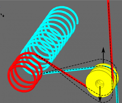
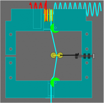
The way I understand it, tensioning works by gradually increasing the distance a cable spans while its anchors remain fixed. In the case of the winch system of this bot, increasing the distance can be achieved by moving the pulleys behind the Z stepper motor:
One design issue is that I created a single shaft for the both pulleys. I have to think about a way to move them in opposite directions that would be simple and adjusting small increments in movement via a screw. The other problem with this approach is that the pulleys are quite inaccessible because of the Z-stepper.
Another options I am investigating are on-cable (in-line) tensioners that work on the same principle: one source of inspiration would be a polywire ratchet tensioner which looks pretty printable and looks like plastic 100% and then some screw-based solutions like this fella's X-axis belt tensioner on instructables.
Edited 5 time(s). Last edit at 05/26/2015 06:10AM by realthor.
For the winch the line should be fixed at extremities of the spool, I just didn't put that in the 3D model.
You are suggesting a tensioning mechanism right at these extremities of the bolt thing which is inline with me having everything onboard this bot
 . This is a good suggestion, I was vaguely thinking of something completely off the bot which is not serving my goals
  .
. I don't have experience with tensioning systems apart from using a guitar peg on an actual guitar so my question is this: considering that I can't completely un-roll the spool, there will always be some coils left on the spool at the extremities on the section that has to go through the nuts. So at least 3-4 coils will always be there. If I would tension the line at these extremities I am not sure the tensioning will propagate to the rest of the line. My guess is that those first 3 coils will tighten very much and because of friction I would only tension that few first coils up to the point of snapping the line.
Is my assumption correct? How can I go around this issue with the tensioning at the extremities of the spool suggestion?
The way I understand it, tensioning works by gradually increasing the distance a cable spans while its anchors remain fixed. In the case of the winch system of this bot, increasing the distance can be achieved by moving the pulleys behind the Z stepper motor:
One design issue is that I created a single shaft for the both pulleys. I have to think about a way to move them in opposite directions that would be simple and adjusting small increments in movement via a screw. The other problem with this approach is that the pulleys are quite inaccessible because of the Z-stepper.
Another options I am investigating are on-cable (in-line) tensioners that work on the same principle: one source of inspiration would be a polywire ratchet tensioner which looks pretty printable and looks like plastic 100% and then some screw-based solutions like this fella's X-axis belt tensioner on instructables.
Edited 5 time(s). Last edit at 05/26/2015 06:10AM by realthor.
|
Re: started designing a new mostly-plastic reprap SCARA with fishing line motion transmission and unorthodox winch for Z May 26, 2015 08:42AM |
Registered: 9 years ago Posts: 1,035 |
Quote
theothermike
Second question: Already tried to run the Morgan-software as-is and move some motors with it? I had no success up to now.
@theothermike: I'm sorry that Morgan doesn't yet work for you. I'm more scared now because your setup is quite like Morgan while mine is just hinting at Morgan. If I restrain the movement to one side it should basically be Morgan without the assisting arms but I have no idea how my string setup will behave as far as the math goes. Haven't yet had a chance to think about that, there are so many design issues I need to iron out right now...
|
Re: started designing a new mostly-plastic reprap SCARA with fishing line motion transmission and unorthodox winch for Z May 26, 2015 09:04AM |
Registered: 9 years ago Posts: 127 |
Of course, math is different. But should be somehow adoptable.
I just wanted to tell you because you said you´re trying to adopt the morgan Firmware...Perhaps I´m doing something fundamentally wrong, but all before you start, check if you can move Motors with the original Firmware...might be there´s a bug in it....
I just wanted to tell you because you said you´re trying to adopt the morgan Firmware...Perhaps I´m doing something fundamentally wrong, but all before you start, check if you can move Motors with the original Firmware...might be there´s a bug in it....
|
Z-axis wire tensioner (idea) May 26, 2015 09:18AM |
Registered: 9 years ago Posts: 1,035 |
Something like this for an onboard tensioning for Z?
Two small pulleys keep the wire vertical while it is tensioned by pulling the line with a screw.
Two small pulleys keep the wire vertical while it is tensioned by pulling the line with a screw.
|
Re: started designing a new mostly-plastic reprap SCARA with fishing line motion transmission and unorthodox winch for Z May 26, 2015 03:11PM |
Registered: 11 years ago Posts: 1,049 |
You sure like to write
and in 5 or 6 different forums?
Perhaps a Rube Goldberg forum also --- but you may need way more complicated steps/mechanisms
and this suggestion may not be complicated enough for your system
You can't PUSH a string so all movement is done by PULL
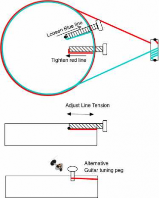
A little drawing of PULL- PULL system (Like WALLY)
with tensioning devices
Here Red and Blue lines can be tensioned separately
either by turning screw in / out or with tuning peg
as the drum rotates the line slides a bit to spread tension on line --
one should move mechanism thru entire movement in tensioning process
Note small pulley takes up Red line while releasing Blue line
Only ONE side provides PULL to do the movement.
??? Why can't line run thru an eyelet (fairlead) in the middle to eliminate triangles
or at least reduce them to something very small --- DOAK!! their I go KISS? ???

|
Re: started designing a new mostly-plastic reprap SCARA with fishing line motion transmission and unorthodox winch for Z May 26, 2015 04:28PM |
Registered: 9 years ago Posts: 1,035 |
Quote
cozmicray
You sure like to write
and in 5 or 6 different forums?
Perhaps a Rube Goldberg forum also --- but you may need way more complicated steps/mechanisms
and this suggestion may not be complicated enough for your system
And yet you're reading all of those
 ... and providing your wise friendly answers
  ... to all of those.
|
Re: started designing a new mostly-plastic reprap SCARA with fishing line motion transmission and unorthodox winch for Z May 26, 2015 11:54PM |
Registered: 11 years ago Posts: 177 |
This is a very nice design. Are you going to limit the arms movement to avoid hitting singularities?
[scara3dprinter.wordpress.com]
[scara3dprinter.wordpress.com]
|
Re: started designing a new mostly-plastic reprap SCARA with fishing line motion transmission and unorthodox winch for Z May 27, 2015 05:19AM |
Registered: 9 years ago Posts: 1,035 |
The plan is to reuse some already existing firmware and Morgan FW seems the right choice. If I only use one side for the ForeArm then it is basically Morgan without the second pair of assisting arms.
The big plan is to use Morgan for a print then home to the other side and print another print using Morgan FW, then, when done, home again to the first home, kicking the part off in the process, etc. This is quite utopic as I don't know if that is possible in the firmware, to have two homing routines. This will be hitting through singularities but only in between prints, which shouldn't be an issue at all.
Do you mean physically? Like Wally has in this picture? I am thinking that the limiting of the arm swing can be done in software but I have no further knowledge about this. My ForeArm has a 150deg of swipe range from a completely extended position. The humerus moves 180deg to each side. Is there a way in software to somehow tell the firmware that the ForeArm can only swing 150 deg from $Home?
OffTopic: Another idea that could possibly be implemented at some point is that I will print on only one side, using Morgan FW, and the dead-zone of the working area can be used to keep a set of inter-changeable heads. Well... still a long time till then .
.
Edited 4 time(s). Last edit at 05/27/2015 06:04AM by realthor.
The big plan is to use Morgan for a print then home to the other side and print another print using Morgan FW, then, when done, home again to the first home, kicking the part off in the process, etc. This is quite utopic as I don't know if that is possible in the firmware, to have two homing routines. This will be hitting through singularities but only in between prints, which shouldn't be an issue at all.
Quote
Evil Monkey
Are you going to limit the arms movement to avoid hitting singularities?
Do you mean physically? Like Wally has in this picture? I am thinking that the limiting of the arm swing can be done in software but I have no further knowledge about this. My ForeArm has a 150deg of swipe range from a completely extended position. The humerus moves 180deg to each side. Is there a way in software to somehow tell the firmware that the ForeArm can only swing 150 deg from $Home?
OffTopic: Another idea that could possibly be implemented at some point is that I will print on only one side, using Morgan FW, and the dead-zone of the working area can be used to keep a set of inter-changeable heads. Well... still a long time till then
 .
.Edited 4 time(s). Last edit at 05/27/2015 06:04AM by realthor.
|
Re: started designing a new mostly-plastic reprap SCARA with fishing line motion transmission and unorthodox winch for Z May 28, 2015 05:37AM |
Registered: 9 years ago Posts: 1,035 |
I am starting to consider in-drum line tensioning something like Wally before the guitar peg. I kind of gave up the "behind the bolts" tensioning as I have no clue how to do that in a simpler way than the already very simple Wally string tensioner. I will stick with the Z tensioning like I sketched above.
With the in-drum tensioning I have to press on 3 loops that are ~12mm apart and I am trying to figure out a one-screw solution for the tensioning part. Wally had 2 screws but I think a one screw and some embedded (in the print) rails would work as well. I am thinking that with 2 screws you have to screw a bit each of them and try to turn both exactly the same, which, without having hands-on experience, seems quite uncomfortable. What do you think is this overkill? Am I trying too hard to reprap this?
Edited 2 time(s). Last edit at 05/28/2015 06:58AM by realthor.
|
Re: started designing a new mostly-plastic reprap SCARA with fishing line motion transmission and unorthodox winch for Z May 28, 2015 07:49AM |
Registered: 9 years ago Posts: 1,035 |
|
Re: started designing a new mostly-plastic reprap SCARA with fishing line motion transmission and unorthodox winch for Z May 28, 2015 10:05PM |
Registered: 11 years ago Posts: 1,049 |
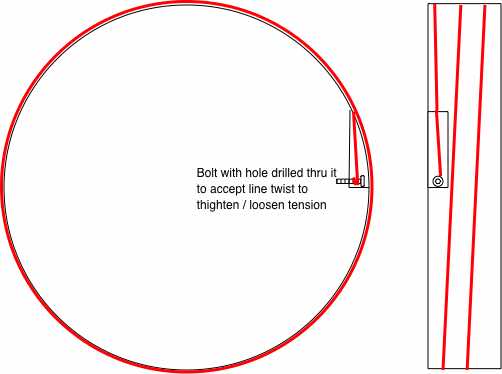
On drum tension rig
Bolt into tight threaded hole
(could even put on locknut)
Just a twist to tighten / loosen

Bolt into tight threaded hole
(could even put on locknut)
Just a twist to tighten / loosen

|
Re: started designing a new mostly-plastic reprap SCARA with fishing line motion transmission and unorthodox winch for Z May 28, 2015 10:18PM |
Registered: 9 years ago Posts: 978 |
|
Re: started designing a new mostly-plastic reprap SCARA with fishing line motion transmission and unorthodox winch for Z May 29, 2015 03:42AM |
Registered: 9 years ago Posts: 1,035 |
How do I go about choosing the fishing line type/diameter? I assume I should know the weight of the SCARA components to calculate the stress on the string?
I am thinking that the fishing line type will be a result of the stress that the system exerts on it, having as parameters the weight of the SCARA component at the radius of rotation, the maximum acceleration that the weight is moved around, etc.?
Thanks.
I am thinking that the fishing line type will be a result of the stress that the system exerts on it, having as parameters the weight of the SCARA component at the radius of rotation, the maximum acceleration that the weight is moved around, etc.?
Thanks.
|
Re: started designing a new mostly-plastic reprap SCARA with fishing line motion transmission and unorthodox winch for Z June 02, 2015 11:02AM |
Registered: 9 years ago Posts: 1,035 |
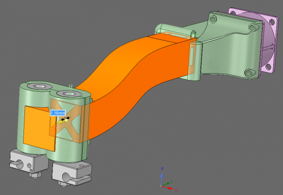
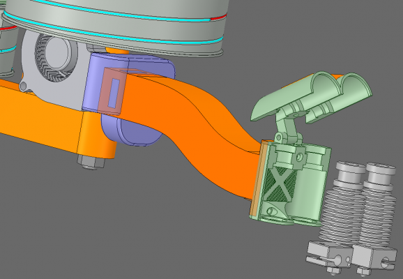
I have pretty much settled on the important mechanical design choices and I am now playing around with some details. One such detail that I have to explore is the bowden hotend mount. I can use neither of Morgan's or Wally's solutions because this is a single arm scara. This requires something else. If there was an already existing design that would apply for my situation please direct me to a STL file.
Otherwise I am exploring a design of my own, something that I can adapt to a dual extruder in the future.
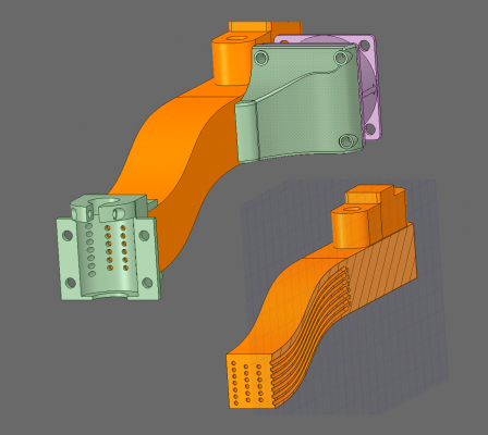
Another idea that i am exploring is keeping the end effector as light as possible and thus moving the fans back on the arm. Instead of a printed funnel that would go the length of the arm I was thinking of embedding tubes in the arm itself. I have read somewhere that they were using this technique to force printing services to put different infill densities within the same part, something that printing services were not allowing. This way the part gets tougher too. I am hoping that this would be similar in my case, although I am sure the following design needs optimizing at the fan-funnel end, where the density of holes is quite high and I am afraid the structure will be deficient in strength.
I think I would have to experiment with capillary density along the arm too but I am guessing the printing time will increase (?) as the structure gets more crowded compared to a normal honeycomb or whatever infill.
I know that a fan with a case enclosing the hotend is a common choice on thingiverse and because the fan is very light the solution above might not be very feasible. But it is awesome and it can get even wilder: have one fan pushing air into the hotend's chamber and another fan on the opposite side of the arm sucking the air to increase its speed and as a result, cooling it even more. If the holes would be narrower near the hotend then it might also benefit from the cooling effect of a gas when it goes from a higher pressure medium to a lower pressure medium.
What do you think? Too wild ? Unfeasible
 ? Not worth it
 ? Awesome?
Edited 1 time(s). Last edit at 06/02/2015 11:02AM by realthor.
Otherwise I am exploring a design of my own, something that I can adapt to a dual extruder in the future.
Another idea that i am exploring is keeping the end effector as light as possible and thus moving the fans back on the arm. Instead of a printed funnel that would go the length of the arm I was thinking of embedding tubes in the arm itself. I have read somewhere that they were using this technique to force printing services to put different infill densities within the same part, something that printing services were not allowing. This way the part gets tougher too. I am hoping that this would be similar in my case, although I am sure the following design needs optimizing at the fan-funnel end, where the density of holes is quite high and I am afraid the structure will be deficient in strength.
I think I would have to experiment with capillary density along the arm too but I am guessing the printing time will increase (?) as the structure gets more crowded compared to a normal honeycomb or whatever infill.
I know that a fan with a case enclosing the hotend is a common choice on thingiverse and because the fan is very light the solution above might not be very feasible. But it is awesome and it can get even wilder: have one fan pushing air into the hotend's chamber and another fan on the opposite side of the arm sucking the air to increase its speed and as a result, cooling it even more. If the holes would be narrower near the hotend then it might also benefit from the cooling effect of a gas when it goes from a higher pressure medium to a lower pressure medium.
What do you think? Too wild
 ? Unfeasible
 ? Not worth it
 ? Awesome?
Edited 1 time(s). Last edit at 06/02/2015 11:02AM by realthor.
|
Re: started designing a new mostly-plastic reprap SCARA with fishing line motion transmission and unorthodox winch for Z June 02, 2015 08:39PM |
Registered: 11 years ago Posts: 177 |
|
Re: started designing a new mostly-plastic reprap SCARA with fishing line motion transmission and unorthodox winch for Z June 03, 2015 03:07AM |
Registered: 9 years ago Posts: 127 |
Interesting idea....but, well, I doubt that it will be efficient in this way.
You should think about maximizing the channels cross section (enhance Diameter/length ratio).
Less channels with larger cross section is much better because flow resistance goes up with pow(radius,4) and those small fans don´t have a high pressure difference!
Hollow square arm with four triangular flow channels ("x in a square") and some crossports might be beneficial for giving low flow resistance and rigid structure.
|
Re: started designing a new mostly-plastic reprap SCARA with fishing line motion transmission and unorthodox winch for Z June 03, 2015 08:15AM |
Registered: 9 years ago Posts: 1,035 |
Quote
theothermike
Interesting idea....but, well, I doubt that it will be efficient in this way.
You should think about maximizing the channels cross section (enhance Diameter/length ratio).
Less channels with larger cross section is much better because flow resistance goes up with pow(radius,4) and those small fans don´t have a high pressure difference!
Hollow square arm with four triangular flow channels ("x in a square") and some crossports might be beneficial for giving low flow resistance and rigid structure.
Mike, thanks for the suggestion. So basically you are saying that I should ditch the low-pressure expansion idea? and I should just focus on efficiently directing the fan's air flow to the hot end's radiator disks. Did I got that right?
Something like this?
|
Re: started designing a new mostly-plastic reprap SCARA with fishing line motion transmission and unorthodox winch for Z June 03, 2015 08:58AM |
Registered: 9 years ago Posts: 127 |
Correct, something like that !
It´s just a Feeling, but you might possibly increase the wall thickness of the square frame a Little bit and decrease that of the "X". Fan inlet port into the arm is big enough (Input area roughly equals Output area ?)?
Just have a look how lightweight mills and airplane Frames are built...perhaps there are other structures/designs which fit your design pilosophy even more?
For better air flow Distribution between the four channels you can additionally implement some oval crossports into the "X"-structure.
Cooling due to adiabatic Expansion Needs a lot of pressure difference to be efficient, so this might not be feasible. (--> Instead: Liquid cooling using flexible hose inside arm ?).
|
Re: started designing a new mostly-plastic reprap SCARA with fishing line motion transmission and unorthodox winch for Z June 03, 2015 09:30AM |
Registered: 9 years ago Posts: 1,035 |
For me hitting equal efficiency with fans mounted directly on the hotend case would suffice, any improvement upon that is a bonus. I was actually thinking that three crossports could be used to push air into the hotends' chamber and the other one could be used as a chimney to take the air away from there. Is this something worth thinking about (having a closed hotend chamber near the very warm air around the nozzles and circulate inside it air from another area, possible less warm) or simply have some more holes into the hotend case to evacuate the warm air would be enough?
I am not thinking about liquid cooling, that would make the arm too heavy. My goal is to offload the end effector of as many items as possible to avoid the centrifugal force to mess up with the G-Code due to inertia. I don't exactly know how smart is the firmware with regards to considering the speed the end effector moves at so that it slows it down when large swipes across the workspace are to be done.
I am not thinking about liquid cooling, that would make the arm too heavy. My goal is to offload the end effector of as many items as possible to avoid the centrifugal force to mess up with the G-Code due to inertia. I don't exactly know how smart is the firmware with regards to considering the speed the end effector moves at so that it slows it down when large swipes across the workspace are to be done.
|
Re: started designing a new mostly-plastic reprap SCARA with fishing line motion transmission and unorthodox winch for Z June 03, 2015 09:15PM |
Registered: 10 years ago Posts: 100 |
|
Re: started designing a new mostly-plastic reprap SCARA with fishing line motion transmission and unorthodox winch for Z June 04, 2015 05:09AM |
Registered: 9 years ago Posts: 1,035 |
Thank you for the suggestion see3d. I will update the sketch but first I need to know your opinions regarding the following:
1) the exit of the blown air: should it be right off the hotends case or should I keep that closed and use one of the crossports as a chimney?
2) with 2 squirrel cage blowers, one pushing air into the hotends chamber and one sucking air from there would I achieve any fraction of the Joule-Thomson (adiabatic expansion as Mike puts it) ?
3) Would one squirrel cage blower be enough to cool the two hotends and the printed part via a redirect of sorts? How are they performing comparing with the normal PC axial fans?
4) Please a PIC with your setup
Edited 1 time(s). Last edit at 06/04/2015 05:09AM by realthor.
1) the exit of the blown air: should it be right off the hotends case or should I keep that closed and use one of the crossports as a chimney?
2) with 2 squirrel cage blowers, one pushing air into the hotends chamber and one sucking air from there would I achieve any fraction of the Joule-Thomson (adiabatic expansion as Mike puts it) ?
3) Would one squirrel cage blower be enough to cool the two hotends and the printed part via a redirect of sorts? How are they performing comparing with the normal PC axial fans?
4) Please a PIC with your setup

Edited 1 time(s). Last edit at 06/04/2015 05:09AM by realthor.
|
Re: started designing a new mostly-plastic reprap SCARA with fishing line motion transmission and unorthodox winch for Z June 04, 2015 08:03AM |
Registered: 9 years ago Posts: 1,035 |
ok, i have done a bit of research on this squirrel blower thingie, seems like a nice solution for my setup even if the noise will be an issue I suppose. If you have your printers in the basement it is ok i suppose but most people have their printers right next to them and need to be cared for like babies.
Anyway, I have answered myself to questions number 3) and 4) while reading.
As promised, some candy:
 and need to be cared for like babies.
Anyway, I have answered myself to questions number 3) and 4) while reading.
As promised, some candy:
|
Re: started designing a new mostly-plastic reprap SCARA with fishing line motion transmission and unorthodox winch for Z June 04, 2015 01:05PM |
Registered: 11 years ago Posts: 1,049 |
You may want to consider a positive displacement pump
ie sawdust puffer on scroll saw.
Aquarium pump (piston , diaphram)
could deliver a good blow thru a small flexible tube???
Air expansion at exit natural cooling (open a scuba tank valve and watch it freeze)
If you need more ---- high volume low pressure sprayer pump.
You could wrap air tube with tubing with liquid nitrogen running thru it, to get real cooling
use highly dehumidified air!
But with so much cooling --- you may need to run higher current extruder heater?
Cooling is smallest of your problems -- winch(s) management!!!!

Edited 1 time(s). Last edit at 06/04/2015 01:09PM by cozmicray.
ie sawdust puffer on scroll saw.
Aquarium pump (piston , diaphram)
could deliver a good blow thru a small flexible tube???
Air expansion at exit natural cooling (open a scuba tank valve and watch it freeze)
If you need more ---- high volume low pressure sprayer pump.
You could wrap air tube with tubing with liquid nitrogen running thru it, to get real cooling
use highly dehumidified air!
But with so much cooling --- you may need to run higher current extruder heater?
Cooling is smallest of your problems -- winch(s) management!!!!

Edited 1 time(s). Last edit at 06/04/2015 01:09PM by cozmicray.
|
Re: started designing a new mostly-plastic reprap SCARA with fishing line motion transmission and unorthodox winch for Z June 04, 2015 02:33PM |
Registered: 9 years ago Posts: 127 |
|
Re: started designing a new mostly-plastic reprap SCARA with fishing line motion transmission and unorthodox winch for Z June 04, 2015 02:50PM |
Registered: 9 years ago Posts: 1,035 |
Why use a scuba tank if I can just submerge the bot underwater and print there  ... no cooling needed
  .
.
I'll stick with either axial fans, the usual type, or this centrifugal squirrel blower. I've seen other builds using the centrifugal type and they only get good reviews.
My question, which is in the air at the moment, is whether using a closed hotend case (as drawn) is preferable to an open case, where air is let out in the hotend area. But I think I'll have to test that after I build the bot.
I know I have better problems to solve but I needed a break from the hard stuff and will need a hotend mount anyway. ...I will get back to the winch eventually, there's no pressure to finish the design. I will do incremental improvements as I get some answers from the true engineers out there... if
 . I also bet my hopes on Nic helping with the winch as he expressed his interesting in testing it, because that needs quite a lot of thinking, CAD skills and engineering experience.
Edited 3 time(s). Last edit at 06/04/2015 03:50PM by realthor.
 ... no cooling needed
  .
.I'll stick with either axial fans, the usual type, or this centrifugal squirrel blower. I've seen other builds using the centrifugal type and they only get good reviews.
My question, which is in the air at the moment, is whether using a closed hotend case (as drawn) is preferable to an open case, where air is let out in the hotend area. But I think I'll have to test that after I build the bot.
I know I have better problems to solve but I needed a break from the hard stuff
 and will need a hotend mount anyway. ...I will get back to the winch eventually, there's no pressure to finish the design. I will do incremental improvements as I get some answers from the true engineers out there... if
 . I also bet my hopes on Nic helping with the winch as he expressed his interesting in testing it, because that needs quite a lot of thinking, CAD skills and engineering experience.
Edited 3 time(s). Last edit at 06/04/2015 03:50PM by realthor.
|
Re: started designing a new mostly-plastic reprap SCARA with fishing line motion transmission and unorthodox winch for Z June 04, 2015 09:19PM |
Registered: 10 years ago Posts: 100 |
I see you got the main answer you needed before I could respond. 
As far as recirculating the air back up the arm, it all depends on the printing environment. If you are in a closed box where you want to regulate the temperature and air currents, then you may want to bring the cooling air back outside the box. This is why some bots use water cooling. Otherwise, it is better to just let it flow out the end of the arm, which will cool better.
The other use of air is a part cooling fan. You could use a similar scheme with a second blower to cool the extruded filament at the tip. It would need to be a different fan, because the cooling requirements of different filaments runs from nil to high, and even varies with different part features.
Sorry, only registered users may post in this forum.
