Threaded polar arm study
Posted by Markus Amsler
|
Threaded polar arm study January 11, 2011 08:13PM |
Registered: 13 years ago Posts: 83 |
I did a short study, if it's possible (theoretically at least) to build a strong and stiff enough polar parallel robot arm.
Short Answer:
Yes
Long Answer:
Structure
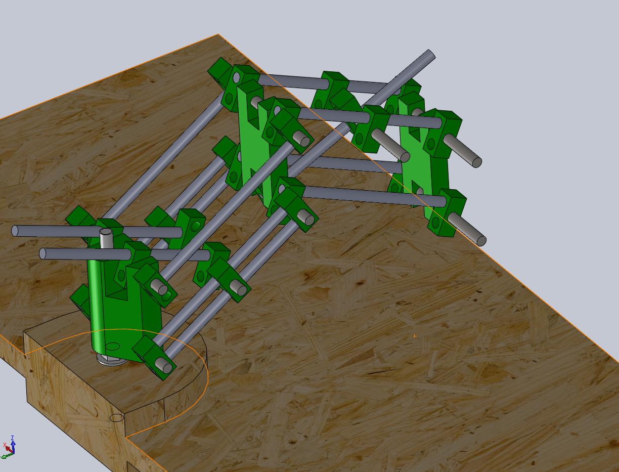
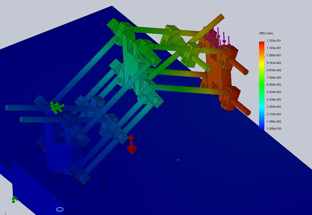
To get the maximum arm deflection with the arm weight and 20N for a tool to around 0.1mm, this thing has to be pretty massive. I ended up with a combination of 12mm steel and aluminium bars. The main axis is currently still a weak spot, but its possible to add some tension rods, or simply make it massive ( 25 mm diameter or so). I'm still not sure how to rotate this thing, but thats no structural problem.
Motion
A good Nema 17 stepper motor with 0.25 Nm pull out torque should be able to pull around 200N on a greased M8 threaded rod. That should be enough, as in the pictured worst case around 150N are required to pull up the arm. It's close, but it should work as I plan to gear down the stepper a bit anyways. 4000 pulse/sec results in 25mm/s on a threaded rod, so 32mm/s head movement speed is possible on a big part of the build area (possibly not everywhere, close to the base it will be slower).
Electronics
Looks like normal mendel grade electronics/steppers should do the job.
There's no principle obstacle to build a precise and fast polar robot arm. The next step is to design it in details, without killing the precision. The promises of easy tool changing and easy build platform modifications, should be worth the effort.
And yeah I'm gonna put that into the wiki, if I have cool name (suggestions are welcome).
Thanks to galaxyman7 for some ideas.
Short Answer:
Yes
Long Answer:
Structure
To get the maximum arm deflection with the arm weight and 20N for a tool to around 0.1mm, this thing has to be pretty massive. I ended up with a combination of 12mm steel and aluminium bars. The main axis is currently still a weak spot, but its possible to add some tension rods, or simply make it massive ( 25 mm diameter or so). I'm still not sure how to rotate this thing, but thats no structural problem.
Motion
A good Nema 17 stepper motor with 0.25 Nm pull out torque should be able to pull around 200N on a greased M8 threaded rod. That should be enough, as in the pictured worst case around 150N are required to pull up the arm. It's close, but it should work as I plan to gear down the stepper a bit anyways. 4000 pulse/sec results in 25mm/s on a threaded rod, so 32mm/s head movement speed is possible on a big part of the build area (possibly not everywhere, close to the base it will be slower).
Electronics
Looks like normal mendel grade electronics/steppers should do the job.
There's no principle obstacle to build a precise and fast polar robot arm. The next step is to design it in details, without killing the precision. The promises of easy tool changing and easy build platform modifications, should be worth the effort.
And yeah I'm gonna put that into the wiki, if I have cool name (suggestions are welcome).
Thanks to galaxyman7 for some ideas.
|
Re: Threaded polar arm study January 11, 2011 10:24PM |
Registered: 16 years ago Posts: 536 |
|
Re: Threaded polar arm study January 12, 2011 10:53AM |
Registered: 13 years ago Posts: 83 |
You're right, it won't go 25mm/s. That's way too optimistic, I just looked at the spec of the stepper motor and did some math. But on a second thought, for any planar move without rotation the rod speed is multiplied by 4 ( *2 for the leverage and *2 because there are 2 rods involved). So 8mm/s rod speed would result in 32mm/s head speed, and that sounds possible.
My main reason for a polar arm isn 't even build area, it's tool change. I tried to figure out how to do it on a mendel, and I couldn't come up with a realistic method. The x-carriage can not move around enough to pick up tools. And you're too constrained in the x-carriage and the mendel frame.
My main reason for a polar arm isn 't even build area, it's tool change. I tried to figure out how to do it on a mendel, and I couldn't come up with a realistic method. The x-carriage can not move around enough to pick up tools. And you're too constrained in the x-carriage and the mendel frame.
|
Re: Threaded polar arm study January 15, 2011 05:47PM |
Registered: 13 years ago Posts: 83 |
I did an experiment. The Nema 17 Zapp Automation / SY42STH47-1684B pulls around 250N at 6mm/s on a M8x1.25 thread without acceleartion. The strange part is, without any load at all the motor won't turn faster than an equivalent of 9mm/s (without acceleration). Also the Stepper Motor Driver 2.3 gets unhealty hot at the rated motor current of 1.68A.
Overall it looks like the motors could handle such a design at reasonable speed.
Overall it looks like the motors could handle such a design at reasonable speed.
|
Re: Threaded polar arm study January 17, 2011 10:04PM |
Registered: 13 years ago Posts: 83 |
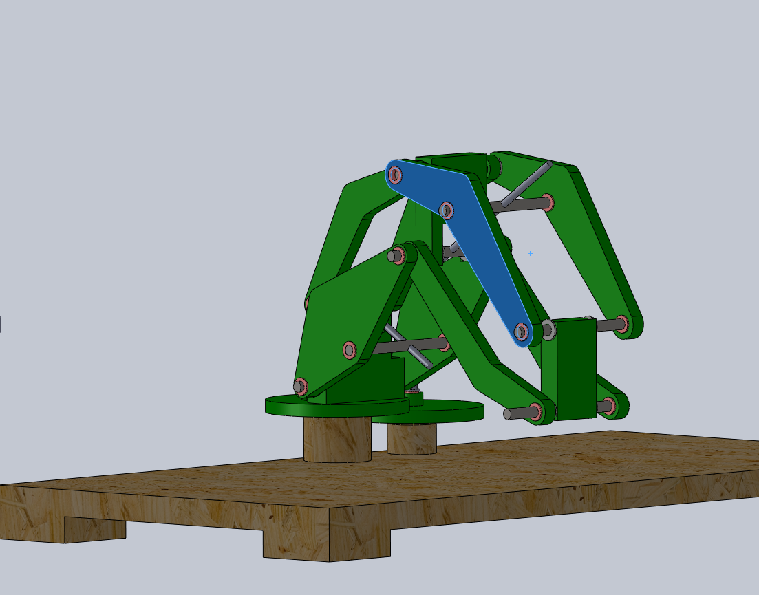
After some hacking around with polar coordinates I managed to calculated how fast the arm end moves along the x axis in the arm plane (out-0-0-c30.png, bright red means >32mm/s, in the green point sits the arm, the white lines are 100mm apart). Thats for the arm geometry shown in polar-3.png and 8mm/s threaded rod speed.
To get a nice big "speed zone", I soon realized the arm has to move as close to the base as possible. Thats why some parts are odly curved, so they don't interfere. Making the second arm part longer also helps for speed, and is no problem as the loads there are much smaller.
I also designed most of the strucutral part out of plastic. Some parts are bit big, but should all fit an a mendel. The stability like this is even better than the previous design with a lot of metal. Instead of using bearing as originally planned, I decided to use bushings. They are cheaper, more precise, should give more lateral stability and are perhaps even printable.
|
Re: Threaded polar arm study February 07, 2011 01:42PM |
Registered: 13 years ago Posts: 7,616 |
FWIW, my tests with the old Gen2 Electronics (half stepping) and M8 rods gave about 1000 mm/min for accelerated movement, 500 mm/min without acceleration. You can get 20% more, but tourque suffers substantially. So our test results are pretty close.
| Generation 7 Electronics | Teacup Firmware | RepRap DIY |
|
Re: Threaded polar arm study February 10, 2011 02:31AM |
Registered: 14 years ago Posts: 198 |
Well I am really glad to have someone to work with on this. Usually if I work on something by myself I never get it done due to lack of motivation. One thing I found to be a huge pain was getting the motor to rotate at a constant speed. I really think a flexible coupling is needed to reduce binding of the threaded rod. Using rubber hose might work, but I have had very little luck doing that. Do you know of any good designs for a diy flexible coupler?
Also, how are you going to rotate the base? In my previous design I found that rotating the base would require a very accurate system if you want to get such high resolution at the tool end. That's why I switched to a linear x axis. It also makes the math a lot easier, and makes it easier to scale up.
Anyways, I like your design, and hopefully we can motivate eachother to actually get something done!
|
Re: Threaded polar arm study February 10, 2011 04:29AM |
Admin Registered: 16 years ago Posts: 13,886 |
... here i posted some images of DIY-flex-couplings ...
For a precise rotating base you can attach a smooth roll with maybe 30mm diameter to the motor, a much bigger disc to the rotating base, use 0.3mm elastic steelwire and wind 3 windings on the motor and 2 windings on the base. When tensioning the friction is enough to drive it slack-free ...
Or use a toothed belt and a standard gear on the motor and a bigger milled one on the base ...
Viktor
--------
Aufruf zum Projekt "Müll-freie Meere" - [reprap.org] -- Deutsche Facebook-Gruppe - [www.facebook.com]
Call for the project "garbage-free seas" - [reprap.org]
|
Re: Threaded polar arm study February 10, 2011 08:24PM |
Registered: 14 years ago Posts: 198 |
I like the couplings. However, I assume those wouldn't support forces along the shaft. It would probably just slip off. There might be a way to put a screw through the shaft and the tube to hold it there. Or maybe use a shaft collar on each end to hold it there. It might rip if you puncture the tubing though.
|
Re: Threaded polar arm study February 12, 2011 12:51PM |
Registered: 13 years ago Posts: 7,616 |
Quote
It would probably just slip off.
Get a pair of either of these and you break the motor before something slips:


(pictures by www.heinze.de)
| Generation 7 Electronics | Teacup Firmware | RepRap DIY |
|
Re: Threaded polar arm study February 12, 2011 09:06PM |
Registered: 14 years ago Posts: 198 |
|
Re: Threaded polar arm study February 14, 2011 10:19AM |
Registered: 13 years ago Posts: 83 |
For the rotating base I thought I would use a timing belt, with a large printed gear on the base. The problem will not be precision but relatively fast turns. I'm not sure what the dynamics will be, but hope acceleration will solve it (or some sort of damping system). There's only one way to check if its possible: building it.
I'm not going to attache the motors directly to the rods. I will use two gears of similar size. This will solve the coupling, and avoids the need for precise alignment of the motor shaft to the rod. Also I can change the gear ratio afterward, if there should be any speed/torque issues.
For the software/electronics I think I go the EMC2 way. This polar stuff won't fit in an arduino, and I'm not about to reinvent the wheel.
I just ordered the bushings/smooth bars, so this is getting real. The first version will be a plywood/abs hybrid, with the big parts made of plywood.
My next step is to complete the design it in details (with fasteners/washers and buildable parts), and then start building it.
|
Re: Threaded polar arm study February 14, 2011 10:06PM |
Registered: 14 years ago Posts: 198 |
Having gears that are made by the reprap will introduce some backlash. Do you have an idea of how much it will be? I suppose that can be fixed within the software by making the motor take up the backlash when it changes directions. That is what I do with my cnc milling machine and it works great. You could also get some gears from amazon here:
[www.amazon.com]
They have great prices on materials, belts, pulleys, and bushings.
So far it looks pretty good. Are you going to use a servo or stepper for the base?
[www.amazon.com]
They have great prices on materials, belts, pulleys, and bushings.
So far it looks pretty good. Are you going to use a servo or stepper for the base?
|
Re: Threaded polar arm study February 15, 2011 07:53AM |
Registered: 13 years ago Posts: 83 |
|
Re: Threaded polar arm study February 16, 2011 04:06AM |
Registered: 13 years ago Posts: 7,616 |
Quote
Where do you get the first one? It looks like it crimps on?
Their german name is "Ohrenklemmen", unfortunately I don't know the english name. I got mine from a local hardware store. They're very common in hydraulics and pneumatics.
Yes, they crimp on with an ordinary pair of nippers.
| Generation 7 Electronics | Teacup Firmware | RepRap DIY |
|
Re: Threaded polar arm study February 22, 2011 08:07AM |
Registered: 13 years ago Posts: 83 |
I was trying to design the gear housing/motor holder for the threaded rod drive. I haven't found a satisfying solution, the two gears take away too much space.
So I'm back to directly attaching the threaded rods to the motor. VDX's DIY-flex-couplings look promising. If I take a M6 threaded rod and file away the threads down to 5mm it fits on the 5mm motor shaft. Using M6 also has other benefits for the design. The pitch difference to M8 (1.25 vs 1) is small, so speed should be no issue.
So I'm back to directly attaching the threaded rods to the motor. VDX's DIY-flex-couplings look promising. If I take a M6 threaded rod and file away the threads down to 5mm it fits on the 5mm motor shaft. Using M6 also has other benefits for the design. The pitch difference to M8 (1.25 vs 1) is small, so speed should be no issue.
|
Re: Threaded polar arm study February 26, 2011 03:15PM |
Registered: 14 years ago Posts: 198 |
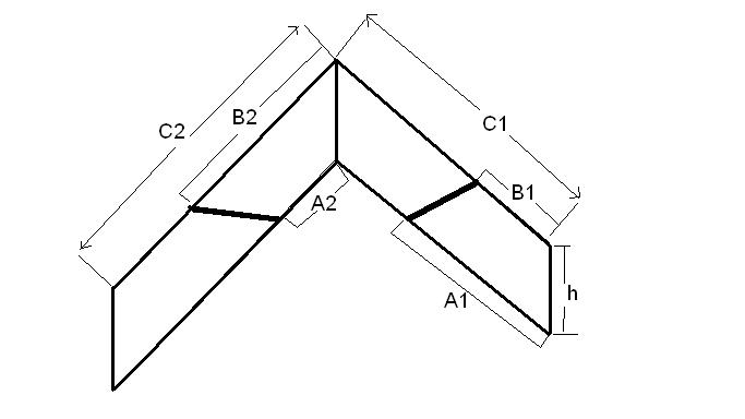
I just worked though the math to figure out how to move the arm so that it will always stay the same distance above the ground, making a straight line. Turns out it is very easy if you set up the positions of the motor and nut right. The equation for making a straight line at a fixed distance above the ground is:
Z=C1( ( -(d1)^2 + h^2 + (A1-B1)^2 ) / (2*h*(A1-B1) ) - C2( ( -(d2)^2 + h^2 + (B2-A2)^2 ) / ( 2*h*(B2-A2) )
The only variables are d1 and d2, the distance from the motor to the nut for each threaded rod. This is controlled by turning the motors. The rest are just measurements of your setup (look at the attachment). All this stuff actually simplifies down to this form once you plug all of that stuff in:
R^2 = k1(d1)^2 + k2(d2)^2
Where k1 and k2 are constants, and R is the radius. This is the equation of an ellipse/ circle! To make it a perfect circle you just need to design the arm so that A1=A2, B1=B2. Then all you have to do is use gcode to make both motors move in a "circle" in relationship with eachother, and the tip of the arm should move at a fixed distance above the ground, z. This way you don't have to keep moving from point to point in very small straight lines, which greatly slows down the travel speed. Gcode already has a circle code built in, so all you need to do is move along the "circle" in the gcode and the arm will move in a straight line. With each layer of the object, the z changes and you follow a different "circle".
Sorry, only registered users may post in this forum.