Home
>
Developers
>
Topic
a reprap without steppers..
Posted by roland
|
a reprap without steppers.. August 29, 2012 11:13AM |
Registered: 14 years ago Posts: 65 |
as i just finished my new ABSPrusa [youtu.be] , i am still a beginner.
Thinking of printing a smaller reprap for my outdoor life: [www.liebwink.de] ..
I think, these heavy never-to-be-replicated stepper motors are a dead end.
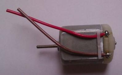
Why not use these cheap small dc motors that speed up to 10.000 rpm.
(3.99 Euro, new, 28 Watt, 9 V and 0,65Ncm at 4400 rpm [www.ebay.de] )
When repap will be able to print electric curcuits, we can print such motors.
We can print the gearing and a disc with lots of holes to count the motor position.
That will do for the z-axis and the extruder.
And for x and y.. when you open one of these cheap digital callipers, you will find an "optical mouse" inside.
putting such optical mouses onto the x- and y-axis, we can easily get the exact position.
And therefore :-) we can replace the tooth belts with printed tooth bars
The cheap dc-motors will be pwm driven, and yes i don't yet understand, why we need such a complicted Sangudingelindon board for $100, when a pic microcontroler for $5 might also do.
and finaly, if the heatbed is only needed to keep the printed objects fixed to the ground, there are others ways, that do not need such an energy waste of 300 Watt.
Which means, a reprap without steppers and heatbed might already be powered by one or two usb ports
and will be a lot cheaper.
Of course there is more: when positioning is done by tooth bars, we can skip the smooth rods and the lineare bearings..
A tooth bar with V-shaped tooths on the upper side and bottom side ..
If you apply this concept also to the z-axis, you get a 100% printable reprap (excluding the printhead, the "optical mouses" and the electronics)
roland
"the little physicist"
first two rules: you always speak yes
Thinking of printing a smaller reprap for my outdoor life: [www.liebwink.de] ..
I think, these heavy never-to-be-replicated stepper motors are a dead end.
Why not use these cheap small dc motors that speed up to 10.000 rpm.

(3.99 Euro, new, 28 Watt, 9 V and 0,65Ncm at 4400 rpm [www.ebay.de] )
When repap will be able to print electric curcuits, we can print such motors.
We can print the gearing and a disc with lots of holes to count the motor position.
That will do for the z-axis and the extruder.
And for x and y.. when you open one of these cheap digital callipers, you will find an "optical mouse" inside.
putting such optical mouses onto the x- and y-axis, we can easily get the exact position.
And therefore :-) we can replace the tooth belts with printed tooth bars
The cheap dc-motors will be pwm driven, and yes i don't yet understand, why we need such a complicted Sangudingelindon board for $100, when a pic microcontroler for $5 might also do.
and finaly, if the heatbed is only needed to keep the printed objects fixed to the ground, there are others ways, that do not need such an energy waste of 300 Watt.
Which means, a reprap without steppers and heatbed might already be powered by one or two usb ports
and will be a lot cheaper.
Of course there is more: when positioning is done by tooth bars, we can skip the smooth rods and the lineare bearings..
A tooth bar with V-shaped tooths on the upper side and bottom side ..
If you apply this concept also to the z-axis, you get a 100% printable reprap (excluding the printhead, the "optical mouses" and the electronics)
roland
"the little physicist"
first two rules: you always speak yes
|
Re: a reprap without steppers.. August 29, 2012 04:07PM |
Admin Registered: 15 years ago Posts: 1,470 |
The heated bed does more than just make parts stick. It helps keep them from warping. Most heated beds draw under 100W, I don't know where you get the 300W figure from.
Controlling DC motors with feedback is a much more complex proposition than controlling stepper motors. Also, those "optical mouse" sensors in digital calipers don't have anywhere near the necessary update speed for proper position feedback on a moving machine.
A 5$ PIC chip is far from the only thing that would be necessary to control a machine like this anyways. You would need something capable of high-frequency PID control, several motor drivers, etc.
|
Help improve the RepRap wiki!
Just click "Edit" in the top-right corner of the page and start typing. Anyone can edit the wiki! |
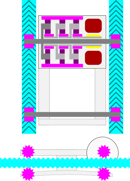
As we will have absolute positioning on all axes, we no longer need the endstops :-)
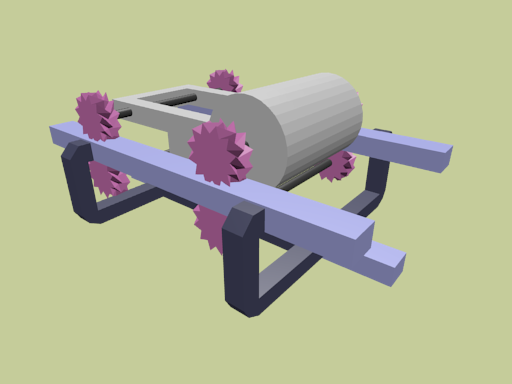
The trolley might look like this:
And we don't really need optical mouses :-)
Simply an IR-diode and an IR-fototransistor onto the tooth bar.
When the reprap is first initialized, it is moved over the tooth bar and the refelection strength is recorded.
There will be a clear period because of the 3mm or 5mm tooths.
This period can be divided by 100 and all the data is simply stored.
This would give a resolution of 0.03 or 0.05 mm :-)
You can tell if this is good enough.
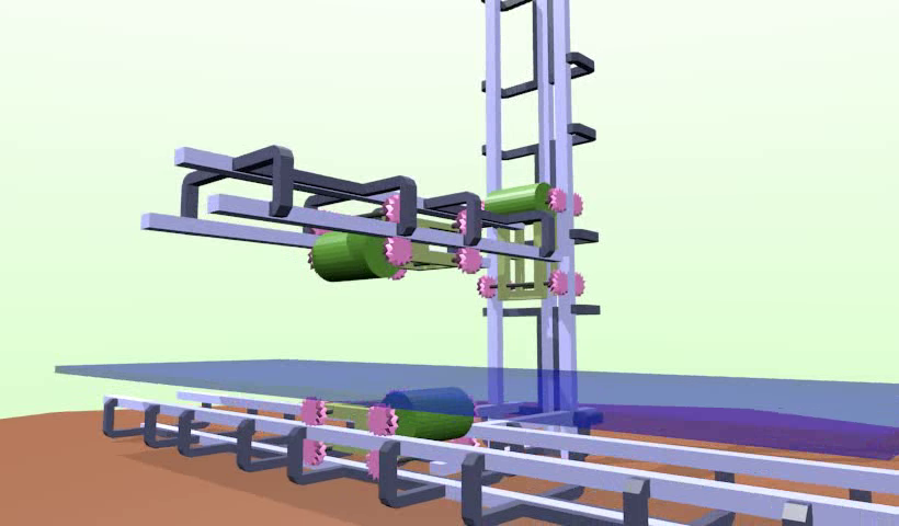
As it is stupid to make a cubic build volume, the y-axis will be the shortest one. Then comes the z-axis, and the x-axis can be as long as you want.
Quickly made a blender animation for you: [youtube.googleapis.com]
A click-in system without any nuts, bolts or washers :-)
It is stupid to screw everything together and have to jig every distance, when you can print everything with far better accuracy.
Such a reprap could be put together in 30 minutes.
These trolleys and tooth-bar-elements should also be able to be connected in such a way, that an "arm" is extending..
Than we are already close to my [www.reprob.org].
And you get an automated storage system by the way :-)
Which is important when the reprob starts to assamble the printed parts itself.
These expensive adurino boards are stupid.
I just sold a fantastic outdoor notebook for less than a Sangudingigonglungo: [cgi.ebay.de]
No 2d inkjet printer is a standalone printer, and a laptop only consumes about 10 Watt, which is nothing compared to the heatbed.
I can program Android phones. you already get smartphones for less than $100 and have a touchscreen, wlan, blootooth, etc.
Such a 90% printable reparp with a pic mircoprocessor and no heatbed can be made for $50
and therfore be sold for $100.
Which means, that everyone will buy such a reprap.
This will be the revolution, you are talking about for more than 10 years.
roland
"the little physicist"
[www.robodurden.com] [www.scriptdoctors.com] [www.wikimedici.com]
just used half of my brain for less than 60 minutes.
as i mostly live outdoor ( [www.liebwink.de] ), i won't have the happiness to build this one.
We would need at least two more guys:
One to print/build/test
Me to program the pic microcontroller (finding a clever positioning algorithm will be a physicists fulltime job!)
The third to handle the software
And don't forget the first two rules:
you always speak yes.
The trolley might look like this:

And we don't really need optical mouses :-)
Simply an IR-diode and an IR-fototransistor onto the tooth bar.
When the reprap is first initialized, it is moved over the tooth bar and the refelection strength is recorded.
There will be a clear period because of the 3mm or 5mm tooths.
This period can be divided by 100 and all the data is simply stored.
This would give a resolution of 0.03 or 0.05 mm :-)
You can tell if this is good enough.
As it is stupid to make a cubic build volume, the y-axis will be the shortest one. Then comes the z-axis, and the x-axis can be as long as you want.
Quickly made a blender animation for you: [youtube.googleapis.com]

A click-in system without any nuts, bolts or washers :-)
It is stupid to screw everything together and have to jig every distance, when you can print everything with far better accuracy.
Such a reprap could be put together in 30 minutes.
These trolleys and tooth-bar-elements should also be able to be connected in such a way, that an "arm" is extending..
Than we are already close to my [www.reprob.org].
And you get an automated storage system by the way :-)
Which is important when the reprob starts to assamble the printed parts itself.
These expensive adurino boards are stupid.
I just sold a fantastic outdoor notebook for less than a Sangudingigonglungo: [cgi.ebay.de]
No 2d inkjet printer is a standalone printer, and a laptop only consumes about 10 Watt, which is nothing compared to the heatbed.
I can program Android phones. you already get smartphones for less than $100 and have a touchscreen, wlan, blootooth, etc.
Such a 90% printable reparp with a pic mircoprocessor and no heatbed can be made for $50
and therfore be sold for $100.
Which means, that everyone will buy such a reprap.
This will be the revolution, you are talking about for more than 10 years.
roland
"the little physicist"
[www.robodurden.com] [www.scriptdoctors.com] [www.wikimedici.com]
just used half of my brain for less than 60 minutes.
as i mostly live outdoor ( [www.liebwink.de] ), i won't have the happiness to build this one.
We would need at least two more guys:
One to print/build/test
Me to program the pic microcontroller (finding a clever positioning algorithm will be a physicists fulltime job!)
The third to handle the software
And don't forget the first two rules:
|
Re: a reprap without steppers.. August 29, 2012 11:21PM |
Registered: 15 years ago Posts: 332 |
There are a fair few problems with that design:
Those motors are reasonably powerful, but have very little torque, and operate at a high rotational speed. They'd need to be massively geared down to the right speed, and the necessary torque increase, and the gears would add prohibitive backlash.
To get absolute positioning, you'd need a >15 bit code to get actual positions if you didn't use endstops. It's not enough to know where you are on the tooth, if you've forgotten which tooth you're on. Also, how do you guarantee constant speeds so that you can integrate position from a simple phototransistor?
As for printing things for better accuracy - each print will slightly reduce in quality, severely damaging the self-replicating aspects of reprap. The advantages of the threaded rods are that you can measure things very accurately, and actually improve quality for every generation.
A netbook isn't much good for controlling a reprap - you need real time control, which while possible with a rtos would require a very low latency port such as a parallel port. A dedicated mcu is a much cleaner solution, so you can use a normal OS.
You really do need a heatbed to print large things well - the warping and shrinkage is otherwise far too high to get decent print adhesion.
There's no way you'll get a full printer for $100 - the raw components simply aren't cheap enough, particularly the electronics, which you'll struggle to get much under $100.
Not that it's bad to think of how to make repraps cheaper, but it's simply not realistic as you describe.
|
Re: a reprap without steppers.. August 30, 2012 02:57AM |
Registered: 14 years ago Posts: 65 |
you toypeople are so pitiable.. always only NO.. always only trying to destroy everything new.. and if something finaly is indestructable, then you think it is perfect :-( i am the born loser.. living in the world of failures. If you would have tried to understand my approach, you would already have read the solutions to your counter-arguments in my lines. and you are so stupid to think that i not already have thought of what you have come up with.. i could have written 10 pages to explain you the concept in more depth, but you would not want to read ten pages, are unable to comprehend 10 pages and have to have the happiness to create these 10 pages youreself anyway. if you are unable to follow the first two rules, please be quiet 
|
Re: a reprap without steppers.. August 30, 2012 03:27AM |
Admin Registered: 16 years ago Posts: 13,884 |
Hi Roland,
... calm down, this is only a methode of brainstorming with pro and contra ...
If you'll read through the forum, you'll find this "servos vs. steppers" every half year or so: [forums.reprap.org]
In the DIY-range steppers with their 'dumb' absolute positioning ability with some ten microns accuracy are much easier to handle than servos with extra mechanics and feedback.
In the comercial range this is different, but then too machines with servos instead of steppers are much more expensive ...
Viktor
--------
Aufruf zum Projekt "Müll-freie Meere" - [reprap.org] -- Deutsche Facebook-Gruppe - [www.facebook.com]
Call for the project "garbage-free seas" - [reprap.org]

less then 10 minutes using half of my brain, just to give you toypeople a little glimpse of what you yourself could achieve if you would follow the first two rules.
We don't even need a big gearing.
We can let such a cheap high speed dc-motor rotate a disc with little magnets.
In the bars there will be some wireing that can create a magnetic field.
So instead of driving the motor with pwm, the trolley is moved by thousands of little magnetic force pulses.
And we just have to reverse polarity of the bar-wires to immediatley reverse the trolleys direction.
On might even get rid of dc-motor and any magnets..
And any gears, sprockets and return to printed linear bearings.
Now i already can see your toy minds only fully rumbling to find little mistakes so that your little toy world stays intact..
This isn't a weekend retreat...
Where you are right now
You can't even imagine what the bottom will be like
Only after diaster can we be resurected
It's only after you've lost everything that you are free to do anything
Nothing is static
Everything is falling apart
This is your life...
Good to the last drop
This is your life...
And it's ending one minute at a time
You are not a beautiful and unique snowflake
You are the same decaying organic material as everyone else
We are all part of the same compost heap
We are the all-singing all-dancing crap of the world
...
Tyler Durden
|
Re: part 3 August 30, 2012 05:17AM |
Registered: 14 years ago Posts: 3,742 |
@roland: I can see that you have never read "How to Win Friends and Influence People".
Bob Morrison
Wörth am Rhein, Germany
"Luke, use the source!"
BLOG - PHOTOS - Thingiverse
Quote
Build it and they will come!
Bob Morrison
Wörth am Rhein, Germany
"Luke, use the source!"
BLOG - PHOTOS - Thingiverse
a high frequency electromagnetic field all along the beams might create a nasty radio interference.
So better a static magnetic field like tiny magnets every 3mm and a high frequency field on the trolley (the replacement for the dc-motor rotating a disc with magnets) that can be shielded.
Now we don't even need the ir-diode/phototransistor
The absolute position can be kept track through the tooth-bar-like-magnetic-field in the beams.
It can even be calculated from the alternating current driving the high frequency field in the trolley.
Just like it is done by the rc brushless drivers..
Lineare bearings will need a smooth rod, which might be difficult to print.
I stil tend to the happy v-shaped gears. the gears will be printed with pla and the tooth bars with abs.
The bottom side rods are pressed hard onto the tooth bar and if after 2 years, the gears have completely disolved, simply print new ones
And again.. as you have lived your entiere lives with only saying no, you will now come to the conclusion that this is science fiction
|
Re: part 4 August 30, 2012 06:06AM |
Admin Registered: 15 years ago Posts: 1,470 |
roland Wrote:
-------------------------------------------------------
> And again.. as you have lived your entiere lives
> with only saying no, you will now come to the
> conclusion that this is science fiction
Most people that propose ideas like yours have no idea how to actually implement it. It sounds as if you are really thinking this through though. A proof-of-concept would be incredibly useful - say, one axis with even somewhat accurate positioning to start with. What you are proposing definitely sounds feasible, just incredibly difficult.
Proposals like this are a good thing. Even if they sound far-fetched, they keep people thinking. You just have to be prepared for lots of opposition, as will always happen with radical ideas.
I encourage you to keep fleshing out this idea.
|
Help improve the RepRap wiki!
Just click "Edit" in the top-right corner of the page and start typing. Anyone can edit the wiki! |
|
Re: part 3 August 30, 2012 06:09AM |
Admin Registered: 12 years ago Posts: 2,569 |
Never mind what you could perceive as negativity, roland - the posters are good willed and only wanting to avoid you some dead ends in their opinion.
Instead, go ahead and try it ! When (if) it works you will be able to come back and post your photos/videos and pose with a triumphant grin.
If you can't do it, you still will learn a lot in the process, and you might come with other better solutions in the mean time.
Most of my technical comments should be correct, but is THIS one ?
Anyway, as a rule of thumb, always double check what people write.
|
Re: a reprap without steppers.. August 30, 2012 06:10AM |
Admin Registered: 16 years ago Posts: 13,884 |
... have you read through some of the search results?
Here is another one for 'linear drives': [forums.reprap.org]
... or a discussion about the needed efforts for magnetic driven linear motors: [forums.reprap.org]
Over the last 6 years several people had this idea too or tried to build something similar ... it seems, there are some other aspects hindering here than 'only ideologics'
Viktor
--------
Aufruf zum Projekt "Müll-freie Meere" - [reprap.org] -- Deutsche Facebook-Gruppe - [www.facebook.com]
Call for the project "garbage-free seas" - [reprap.org]
|
Re: a reprap without steppers.. August 30, 2012 07:58AM |
Registered: 15 years ago Posts: 376 |
A rapid prototype machine which you have sitting on your desk is designed to enable you to try out off the wall designs that may or may not work.
I suggest you try to build this device or at least one axis and do some trials. Even if it moves poorly but can be seen to work, this may inspire others to chip in more constructively with ways to improve what you have. Post the designs so others can print them off change it about.
I have had experience of this first hand with my delta robot. The one I built barely worked at all, but it did inspire Johann to build his much better Rostock which I'm sure in turn in turn will inspire others.
If you get a linear rail to work with simple motors and some sort of encoder feedback this will be of interest to many people including myself.
In short... have a go, even if it doesn't work we will all learn something and won't think any worse of you for trying.
|
Re: a reprap without steppers.. August 30, 2012 08:06AM |
Admin Registered: 16 years ago Posts: 13,884 |
Hi Roland,
... I've sort of remembered our first contact 3 years ago: [forums.reprap.org]
What's driving you around? - how were your experiences since then?
Viktor
--------
Aufruf zum Projekt "Müll-freie Meere" - [reprap.org] -- Deutsche Facebook-Gruppe - [www.facebook.com]
Call for the project "garbage-free seas" - [reprap.org]
want to write it down, so i can forget about..
you forget about absolute positioning. that again is only this christian world of fearfully clinging to control.
With the absolut location at every moment, you also get the speed and the acceleration.
And since Newton, this is enough to caculation the motion.
During initialisation of the reprap, the printhead is moved along all axes to "calculate" the moment of inertia.
And during printing, the pic microcontroller does not get a list of points to move towards, it will be given a curve to follow.
In the beginning the printhead already makes a circle around the footprint to ensure constant flow of the melted plastic.
When the circle is complete, the pic microcontroller will be on track and printing can begin
Yes, this zig-zag to fill the inner volume will create the biggest problem. But this zig-zag could be smoothed..
.. When i first saw the t5 toothbelt, i wondered how precise position can be done with a stepper motor.
But i did not worry and imagined the possibility to create intermediate steps by constantly powering the motor..
Later i smiled when reading about the micro-stepping feature.
So whatever you read here about this new approach, once on the road, it will get even better than this.
roland
the born loser
i lose - you fail.
look how my concept has evoled over the last view hours and how many new ideas went into it. And than look how many ideas you have contributed. Zero. Nothing. And like 7 years old kids you keep insisting that you are no failures, holding up the holy bible that we should dissemble to each other how special we are.
To start with, we could use extruded H-profile aluminium (5 times cheaper than pla for now) with 16 bearings running in the two beams.
Into the third lower beam, lots of 2mm square iron bars are glued parallel with an offset of 3mm each.
Onto each bar, two 3mm neodym magnets are glued, With every next bar having opposite polarity.
One "force unit" will consist of three coils spooled onto upside down U-formed 2mm iron rod, 10 mm height.
Offset of these three parallel electric U-magnets should be 4mm, so when putting them over the neodym-rail, they will be 120° out of phase.
I have just made this up during lunch. But an ordinary stepper driver might now be able to operate this force unit.
There are people on [www.thingiverse.com] , who have better knowlede on motor design.
As the trolley will be at least 150mm long, one could attach ten of these force units.
This will give a very very powerful drive
Edited 1 time(s). Last edit at 08/30/2012 10:59AM by roland.
To start with, we could use extruded H-profile aluminium (5 times cheaper than pla for now) with 16 bearings running in the two beams.
Into the third lower beam, lots of 2mm square iron bars are glued parallel with an offset of 3mm each.
Onto each bar, two 3mm neodym magnets are glued, With every next bar having opposite polarity.
One "force unit" will consist of three coils spooled onto upside down U-formed 2mm iron rod, 10 mm height.
Offset of these three parallel electric U-magnets should be 4mm, so when putting them over the neodym-rail, they will be 120° out of phase.
I have just made this up during lunch. But an ordinary stepper driver might now be able to operate this force unit.
There are people on [www.thingiverse.com] , who have better knowlede on motor design.
As the trolley will be at least 150mm long, one could attach ten of these force units.
This will give a very very powerful drive


Edited 1 time(s). Last edit at 08/30/2012 10:59AM by roland.
|
Re: part 6 August 30, 2012 11:18AM |
Registered: 14 years ago Posts: 3,742 |
|
Re: a reprap without steppers.. August 31, 2012 07:26AM |
Registered: 11 years ago Posts: 120 |
like many "mad" scientist (mad as in a good way), you are rumbling all new ideas before thinking of what the goal was of your initial idea. Try to get the real goal in perspective and then retink about what you are trying to think about.
and read that book mentioned by mr Morrison ...... it will probably help you achiving realized ideas when you figured out what you want to do.
Edited 2 time(s). Last edit at 08/31/2012 07:29AM by Weedz.
and read that book mentioned by mr Morrison ...... it will probably help you achiving realized ideas when you figured out what you want to do.
Edited 2 time(s). Last edit at 08/31/2012 07:29AM by Weedz.
i guess, this will be the last post for a long time. will leave for a new [www.liebwink.de] round tomorrow, than another in october, wintertime with my house-boat, and back home in springtime.
With these 3mm neodymium magnets, step size will be exactly 1mm, i guess.
Using 1/16 microstepping, that would give a resolution of 0.06mm. As i am printing with a 0.5mm nozzle, this might already be enough. Than we could return to the endstops and would not need the realtime-position-read at all and my "flight-print".
Using the magnetic drive for the z-axis might be quite power consuming. So a little break might be fine, that is only lifted when an z-move is about to occur.
And as i don't want to open another loser-thread, here my idea to do without a heatbed:
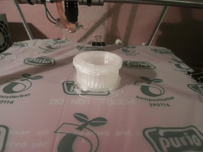
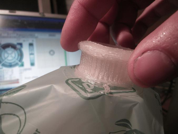
A printed flat box with thousands of little holes and a printed little vaccum pump to create a little underpressure.
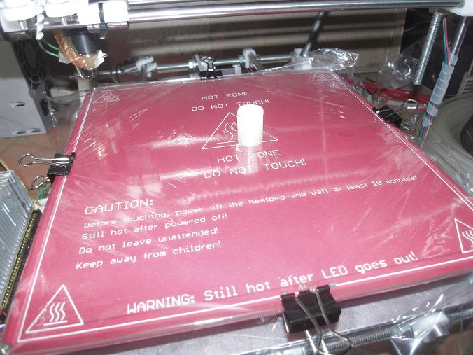
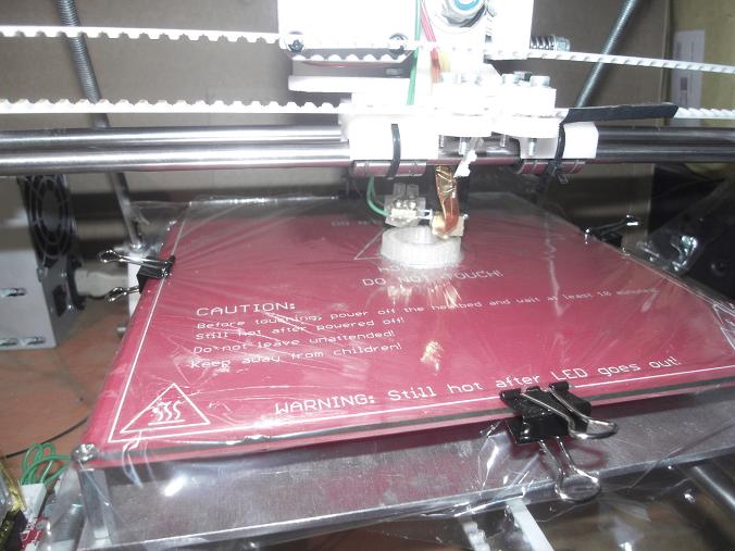
I tested this cheap transparent PE kitchen foil that i just clamped onto the glass pane.
First print went well, but when i happily reused the foil, a bigger pulley got ripped off after 6mm height.
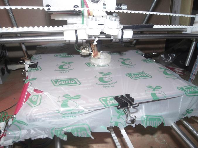
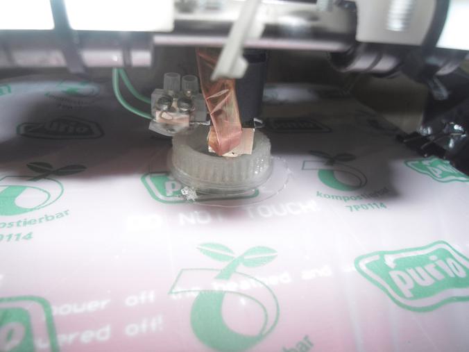
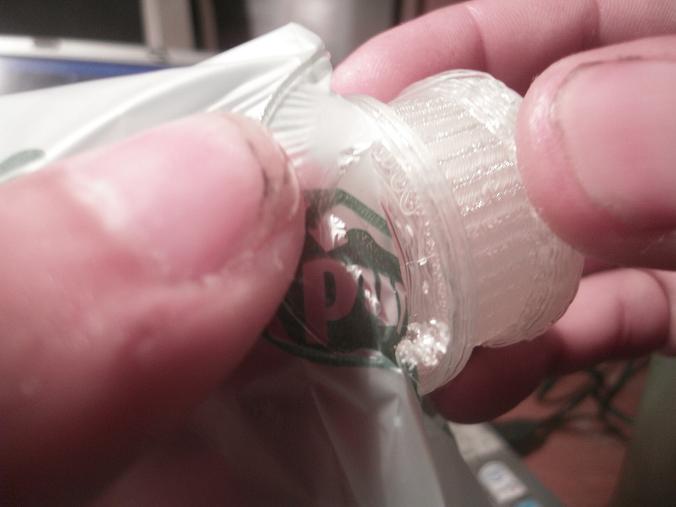
Of course, PLA foil might be the best choice. So i just tested these bio-degradable 15l trash bags
with full success.
As the foil was only fixed on four edge points of the glass plane, at 2cm height, the pulley started to shake,
When in the end i tried to rip of the foil, this was very hard but indeed yes, the foil went off without having melted into the pla :-)
Such a 15 liter (or 10?) bag lasts for up to 5 prints and costs about 10 cents each. Which makes about 2 cent for a print wich equals the cost of 1 hour heatbed at 100 Watts.
And mulch film made of PLA-blend [en.wikipedia.org] should be a lot cheaper.
roland
"never do great things alone - for alone, you always lose."
"there are three beings in the western world who are always right: God, Jesus and Santa Claus."
you are living in a toy world.
With these 3mm neodymium magnets, step size will be exactly 1mm, i guess.
Using 1/16 microstepping, that would give a resolution of 0.06mm. As i am printing with a 0.5mm nozzle, this might already be enough. Than we could return to the endstops and would not need the realtime-position-read at all and my "flight-print".
Using the magnetic drive for the z-axis might be quite power consuming. So a little break might be fine, that is only lifted when an z-move is about to occur.
And as i don't want to open another loser-thread, here my idea to do without a heatbed:
A printed flat box with thousands of little holes and a printed little vaccum pump to create a little underpressure.
I tested this cheap transparent PE kitchen foil that i just clamped onto the glass pane.
First print went well, but when i happily reused the foil, a bigger pulley got ripped off after 6mm height.


Of course, PLA foil might be the best choice. So i just tested these bio-degradable 15l trash bags
with full success.


As the foil was only fixed on four edge points of the glass plane, at 2cm height, the pulley started to shake,
When in the end i tried to rip of the foil, this was very hard but indeed yes, the foil went off without having melted into the pla :-)
Such a 15 liter (or 10?) bag lasts for up to 5 prints and costs about 10 cents each. Which makes about 2 cent for a print wich equals the cost of 1 hour heatbed at 100 Watts.
And mulch film made of PLA-blend [en.wikipedia.org] should be a lot cheaper.
roland
"never do great things alone - for alone, you always lose."
"there are three beings in the western world who are always right: God, Jesus and Santa Claus."
you are living in a toy world.
read on [de.wikipedia.org] that PLA is already used as "extruded pla-fiber reinforced plastic".
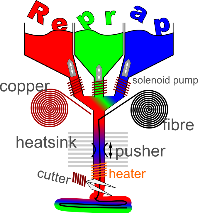
And as it took me the entire last two weeks to build a new carbon bike trailer coupling, i "redesigned" the printhead today:
Yes
And thanks to vdx, my 3 year old post about a new way of printing circuit boards is already linked in. Surely no one of you has followed that happy idea.. But if a carbon fiber can be printed, so can copper wire
And yes, broadening that old conecpt, one side of the 3d-circuit-board will have lots of tiny coils, another side lots of tiny loops and side C again lots of coils.
After printing, into each coil of side A, a little hot metal pin will be pushed, thereby short-circuiting the combined wires,
on side B, the loops will be cut with a scissor and on side C, hot sockets will be pushed through the coils that will then be popluated with the electronic components.
Okay, this now is science fiction It will need a lot of experimentation to get everything right.
But extruding fibers would be sooo nice. And this multicolor feature was just drop-off as i had to temporarily cool down the melted plastic to push the injected fiber forwards(backwards).
roland
alias Robo Diogenes
alias Ron Bombadil
alias [www.RoboDurden.com]
"fascism is the reduction of the complex."
and
"ignorance is a sign of abuse."
and
"understanding is closeness."
or as scientology puts it: "understanding is affinity."
failures always fail to understand - all they can do is to learn
And as it took me the entire last two weeks to build a new carbon bike trailer coupling, i "redesigned" the printhead today:

Yes
And thanks to vdx, my 3 year old post about a new way of printing circuit boards is already linked in. Surely no one of you has followed that happy idea.. But if a carbon fiber can be printed, so can copper wire
And yes, broadening that old conecpt, one side of the 3d-circuit-board will have lots of tiny coils, another side lots of tiny loops and side C again lots of coils.
After printing, into each coil of side A, a little hot metal pin will be pushed, thereby short-circuiting the combined wires,
on side B, the loops will be cut with a scissor and on side C, hot sockets will be pushed through the coils that will then be popluated with the electronic components.
Okay, this now is science fiction
It will need a lot of experimentation to get everything right.But extruding fibers would be sooo nice. And this multicolor feature was just drop-off as i had to temporarily cool down the melted plastic to push the injected fiber forwards(backwards).
roland
alias Robo Diogenes
alias Ron Bombadil
alias [www.RoboDurden.com]
"fascism is the reduction of the complex."
and
"ignorance is a sign of abuse."
and
"understanding is closeness."
or as scientology puts it: "understanding is affinity."
|
Re: a reprap without steppers.. September 03, 2012 10:36AM |
Registered: 11 years ago Posts: 11 |
|
Re: a reprap without steppers.. September 03, 2012 03:30PM |
Registered: 12 years ago Posts: 1,236 |
Yeah, it seems insulting but it is probably something like Asperger's syndrome. We had another guy like that a while ago.
There might be some good ideas in there, but few have the tolerance to find out. There is a line between madness and genius, but usually it falls more to the madness side.
There might be some good ideas in there, but few have the tolerance to find out. There is a line between madness and genius, but usually it falls more to the madness side.
|
Re: a reprap without steppers.. September 04, 2012 03:08AM |
Registered: 13 years ago Posts: 406 |
I did build a FDM some 20 years ago similar to part8 above, it had a single head and tiny sugical scissors to cut the
fillament, it was for medical implant research, it worked well so I see no reason for part8 not to work.
Roland comes across as abrasive but his ideas have merit.
Random Precision
fillament, it was for medical implant research, it worked well so I see no reason for part8 not to work.
Roland comes across as abrasive but his ideas have merit.
Random Precision
|
Re: a reprap without steppers.. September 04, 2012 03:25AM |
Admin Registered: 16 years ago Posts: 13,884 |
... maybe some associated ideas here too: [reprap.org] - click on the "discussion"-tab
Edited 1 time(s). Last edit at 09/17/2012 02:48AM by VDX.
Viktor
--------
Aufruf zum Projekt "Müll-freie Meere" - [reprap.org] -- Deutsche Facebook-Gruppe - [www.facebook.com]
Call for the project "garbage-free seas" - [reprap.org]
Edited 1 time(s). Last edit at 09/17/2012 02:48AM by VDX.
Viktor
--------
Aufruf zum Projekt "Müll-freie Meere" - [reprap.org] -- Deutsche Facebook-Gruppe - [www.facebook.com]
Call for the project "garbage-free seas" - [reprap.org]
Only when you have the courage to change everything, different improvements can improve each other and only then can optimization escape a local minima advancing to something worth labeling "next generation".
When printing wires, printing one z-layer after another would be a drawback.
But luckily, the z-axis drive will be like the others, and it the brake is replaced with a long spring to more or less counter-balance the weight, the x-axis might be droped and lifted as quickly as the printbed is moved forwards and backwards.
The nozzle of the extruder should be a tube of about 1.5mm, than the three solenoids of the "force units" can be printed as well.
And yes, this temporarily cooling down to move the palstic/fiber was just the first solution that came into my mind.
Only mentioned it, because you no-men would never have been able to find one.
A better and more clever way might be the use of ultrasound.
With two pieozoelectic speakers injecting a 229 kHz Sound at top and bottom into such a 1.5mm tube, standing waves would build up inside. This standing wave should deform the 0,5mm extruded plastic string accordung to the preassure minima and maxima of the standing wave.
When the upper speakers frequency is slightly increased, the standing wave moves upwards, thereby preventing the plastic to drop downwards. Slightly increasing the lower speaker would propel the plastic down onto the printbed.
I chose 229 kHz, because than the wavelength would be 1.5mm and the string might also be centered automaticly :-)
But i also found quite interessting wiki pages:
Acoustic levitation: [en.wikipedia.org] Ultrasonic motor: [en.wikipedia.org] Ultrasonic welding: [en.wikipedia.org]
And the good news: There is a thermoplastic having strong piezoelectricity [en.wikipedia.org]
"Compared to other fluoropolymers, it has an easier melt process because of its relatively low melting point of around 177 °C."
more to read, Piezoelectric motor: [en.wikipedia.org]
Ultrasound motors are already used in objective lenses: [de.wikipedia.org]
Canon: USM (Ultrasonic Motor)
Nikon: SWM (Silent-Wave-Motor)
SONY: SSM (Super Sonic Motor)
Olympus: SWD (Supersonic Wave Drive)
Pentax: SDM (Supersonic Dynamic Motor)
Sigma: HSM (Hyper Sonic Motor)
Tamron: USD (Ultrasonic Silent Drive)
Tamron: PZD (PieZo Drive)
roland, the born loser
"who fears losing, already has become a failure."
Edited 1 time(s). Last edit at 09/04/2012 01:26PM by roland.
|
Re: part 6 September 08, 2012 04:31PM |
Registered: 12 years ago Posts: 313 |
roland Wrote:
-------------------------------------------------------
> One "force unit" will consist of three coils
> spooled onto upside down U-formed 2mm iron rod, 10
> mm height.
> Offset of these three parallel electric U-magnets
> should be 4mm, so when putting them over the
> neodym-rail, they will be 120° out of phase.
> I have just made this up during lunch. But an
> ordinary stepper driver might now be able to
> operate this force unit.
So, you just "invented" the linear motor? How exactly is this a better solution than a conventional belt- or cable-driven linear actuator powered by a NEMA17 stepper motor, as used in the current mainstream printers?
And, you know, Edison said: Genius is one percent inspiration, ninety-nine percent perspiration. What this means is that there is a vast amount of effort needed between coming up with an idea and making it actually work. But you have nothing but insults for people who care about the missing 99%...
|
Re: a reprap without steppers.. September 08, 2012 05:14PM |
Admin Registered: 16 years ago Posts: 13,884 |
... this is a theme regularly reactivated here in the forum - one of the first threads regarding printing LD's was in 2007: [forums.reprap.org]
Edited 1 time(s). Last edit at 09/08/2012 05:16PM by VDX.
Viktor
--------
Aufruf zum Projekt "Müll-freie Meere" - [reprap.org] -- Deutsche Facebook-Gruppe - [www.facebook.com]
Call for the project "garbage-free seas" - [reprap.org]
Edited 1 time(s). Last edit at 09/08/2012 05:16PM by VDX.
Viktor
--------
Aufruf zum Projekt "Müll-freie Meere" - [reprap.org] -- Deutsche Facebook-Gruppe - [www.facebook.com]
Call for the project "garbage-free seas" - [reprap.org]
|
Re: a reprap without steppers.. September 11, 2012 06:58PM |
Admin Registered: 13 years ago Posts: 730 |
There is a big archive of motor related projects (including linear drives) on the wiki here
[reprap.org]
[reprap.org]
|
Re: a reprap without steppers.. September 17, 2012 01:34AM |
Registered: 11 years ago Posts: 482 |
Hey Man... (or woman?). Great post - I have a LOT of comments for you : )
I totally appreciate what you are saying here, and the basic idea. The way I like to reframe it is, most people aren't gonna be like "hell yeah!" and write it. They'll be like "hell yeah!" but think its not worth the extra time to write it because its good. They quietly agree and move on.... hoping you'll carry on. You know this is the case when so many people buy something, but never leave feedback - feedback is usually from the extremes...that leaves Dr. No's and Negative Nancies, while the most motivated tend to keep their positive ideas shared with fewer people. Its a problem I find largely on forums that I don't find in real life. Its why I really wanna form a DC reprap group to meet up and exchange ideas since this works in my life where I've selected only for people who talk and think positively and share ideas openly.
I have a LOT of theory on this psychology (and your original post, which I'll get to. I had a very similar idea before). I'm drawing on Tony Robbins and others, TED talks, and including my personal experience in a large government lab during my Post-doc. Basically, the scientist is motivated by something exciting and new because he/she created it, found it, made it work, did something different; in other words, they are motivated by the significance of it. Therefore, when you present a new idea, you're challenging them in a universal way - potentially negatively. In one case, you present potential progress in a field where someone else is used to making their name, so you unintentionally threaten their significance by overshadowing them. In another case, you threaten the scientist who values consistency, but now fears having to learn new technology or switch how they do things for no extremely obvious gain. In another case, your progress could make scientists in general feel less significance because you are moving ahead or thinking so differently. Of course, others are just arrogant and don't care about your idea, but I really believe those are a not around here.
The reframe here is that you are creating impact ever time you get negative responses, make waves, get laughed at, told you are wrong. It is the very definition of making change and creating progress, because you are feeling so much resistance...the only thing missing are the results. A good scientist would then be motivated to prove every naysayer wrong with this new mentality: )
You can only shift your perspective (change your expectations) or communicate your needs better. Since the ladder is overly needy for a faceless, online forum, I would just work towards creating a different impression of what's really going on around you, internally, using the reframe tactics I've given examples of.
My personal goal is to cultivate a field of great scientists who think positively. I share most of my ideas with them, and the progress we make is astronomical compared to anything I've every seen. The key to doing this is letting go of your own significance and realizing that by helping others you advance your entire sub-field, which is both better for your significance and your buddies in the long term. As a result, if you come up with something, someone else uses it, you don't feel taken advantage of, you then do the same, share ideas openly, and everyone moves forwards with lightning speed! Hell, in my workgroup we are already planning the 3D printing of cars, but I won't present it here because I'll be laughed at or ignored.
So sadly enough the real benefit of the forums may be to work on incremental progress that doesn't threaten reprap by creating a huge shift...maybe they aren't ready for $100 printers yet, but I am.
No on to the idea... I actually started, debating my friend HEAVILY for 3 months against steppers. I fell in love with the idea of super super simple DC motors - they are dirt cheap and speed is controlled with voltage. Two wires only! Why the heck do you need 4 or 6? Didn't make sense to me. My friends argument was that steppers are better because they don't die due to brush failure. I thought, how much could it matter? Tons of devices uses brushed motors - even electric drills. I ended up building so many servos from scratch. What I found was that the drive for a DC motor is more complex that I first thought. You need feedback, like an encoder or infrared distance sensor, which you dont for steppers. You also need an H bridge to deliver both positive AND negative current, which you need only a little more complexity for steppers. Also, the total lack of gearing because a huge problem as far as reliability. In the end, we concluded both designs were similar in cost and performed similarly - with the steppers being so much more reliable, and the brushed servos costing slightly less in the end - it was a no brainer to pay the extra $10 for steppers. Actually, the brushed method is more powerful in some cases and uses less electrical energy.
I could break down the math for you. DC motor + gearboxes = servo. Servos are $30 for decent ones. You can get EXI's for $14, they deliver a mad 250 oz-in of force. Now you need an encoder - magnetic with IC = $17. Infrared sensors = $14. Now you need a servo controller. Pololu maestro = $2 per motor for the 24 servo kit. So all in all, $14 + $14 + $2 = $30 per channel.
For Steppers, you get an arduino mega ramps for $120 on ebay assembled, with wiring. That gives you 5 steppers control and all the accessories like nozzle power. Now you spend $15 on a Kysan Nema 17 bipolar stepper motor and you are immediately done. 5 steppers = $75. Total price per motor? $195 / 5 = $39.
Conclusion: All in all, you don't save much with DC motors, and they are crappy and unreliable. But it would work and be cheaper! Also, the obvious advantage is you dont need to by a 24-servo controller, but you do need to buy a 5-motor RAMPS....you need at least 4 anyway (Extruder).
Measure once, Cut twice, Print 3 times.
|
Re: a reprap without steppers.. September 17, 2012 01:48AM |
Registered: 11 years ago Posts: 482 |
NewPerfection Wrote:
-------------------------------------------------------
> The heated bed does more than just make parts
> stick. It helps keep them from warping. Most
> heated beds draw under 100W, I don't know where
> you get the 300W figure from.
>
Correct me if I am wrong...I've relatively new, But I don't understand how the heated bed helps prevent warping.
Warping is caused by rapid cooling, but also by building up so much heat over multiple layers that the nozzle force or ABS weight itself begins to compact a structure prematurely. In everyway I've imagined or tested empirically, the heated bed seems to make these problems FAR worse. In fact, I exclusively print without a heated bed. Heres an example of my print (the base is 79 mm) and it is about 45mm tall: [www.dropbox.com] and [www.dropbox.com]. IMO, the only reason to have a heated bed is to make the initial layer stick well, in the absence of a good invention like adding paper or LDPE as Roland posted further below?
In fact, I point a very large high speed fan onto my build because I find that the rapid cooling fixes two or three things:
1) Bridges can be grown sideways (realistically at a 15 degree angle or so).
2) The material cools and forms more straight and without warping
3) The nozzle doesn't "stick" to and ruin previous layers, ever.
0.02, but I have to agree with Roland wholly unless shown otherwise!
Edited 1 time(s). Last edit at 09/17/2012 01:49AM by Simba.

Sorry, only registered users may post in this forum.