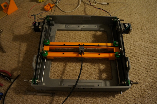
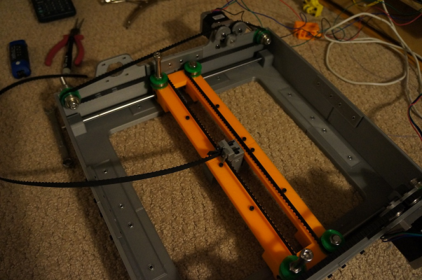
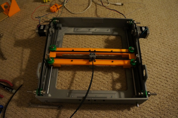
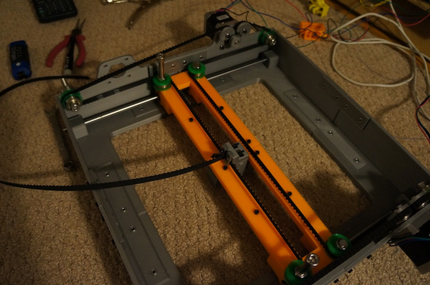
HBot using fishing line
Posted by Polygonhell
|
Re: HBot using fishing line November 10, 2012 03:32PM |
Registered: 11 years ago Posts: 374 |
Did a motorized test this morning and confirmed there is no wobble in X during Y moves, and the X bar doesn't move at all when x moves are initiated.
At this point I need to do a full redesign to "rev 2" in order to make some improvements. Hopefully I can get to that in the coming weeks.
At this point I need to do a full redesign to "rev 2" in order to make some improvements. Hopefully I can get to that in the coming weeks.
|
Re: HBot using fishing line November 10, 2012 08:44PM |
Registered: 11 years ago Posts: 374 |
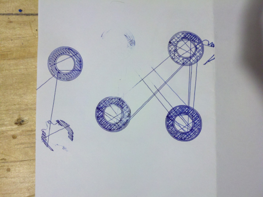
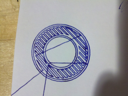
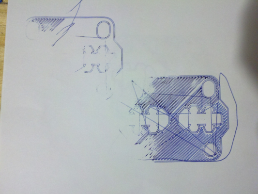
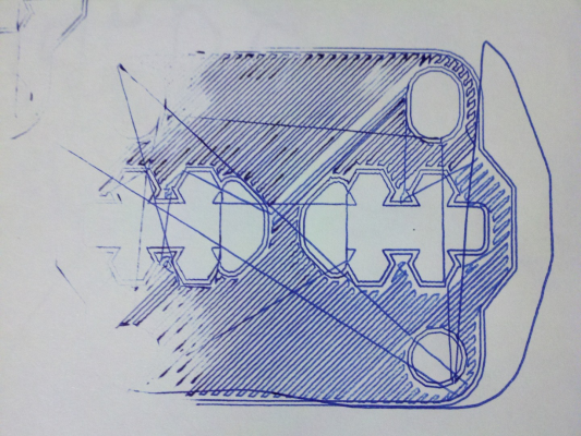
Hot-glued a pen to the carriage to do some tests as a plotter. Results show positioning repeatability is extremely good - no signs of skipped steps or cable slip, even during 140mm/sec travel moves.
The only issue I found was lots of oscillation at the head after direction changes. This isn't surprising since the H-bot has quite a lot of cable length with which to oscillate. It's probably made worse by the fact that the pen is poorly mounted, and that the gcode I was running as written for my working printer so the settings don't really make sense for this bot.
Video is here: [vimeo.com]
A few pictures are below.
Bottom right circle has multiple layers overlaid perfectly.
Close up of first layer plot, you can see the oscillation in the path on the infill.
First layer of some random parts.
Close up of above. Infill is misaligned in parts because the paper slipped.
|
Re: HBot using fishing line November 11, 2012 03:08PM |
Registered: 11 years ago Posts: 482 |
|
Re: HBot using fishing line November 11, 2012 07:33PM |
Registered: 11 years ago Posts: 939 |
I pretty much know what my issues are, one of my LM8UU's was a bit sticky, that coupled with the drive pulleys being marginally out of round, the larger pulley exacerbates the effect. I agree the geometry looks feasible, but it's very sensitive to mechanical issues.
The fishing line seems completely workable, all any system really needs is a mechanism to apply tension. I can reliably run at speeds of 600+mm/s with acceleration set at 9000.
I'll make up some new stepper mounts and drive pulleys that are smaller this week if I get a chance.
The fishing line seems completely workable, all any system really needs is a mechanism to apply tension. I can reliably run at speeds of 600+mm/s with acceleration set at 9000.
I'll make up some new stepper mounts and drive pulleys that are smaller this week if I get a chance.
|
Re: HBot using fishing line November 11, 2012 07:44PM |
Registered: 11 years ago Posts: 374 |
I haven't tried speeds that high yet, but I don't anticipate issues.
My main concern is oscillation at the head due to the long cable. I think it can be worked around, just a question of how much of a pain it will be.
I'd be interested to see if you see the same oscillation if you were to run some plotter tests.
Also, it looks like you are using thicker monofilament line instead of braided line. Have you had issues with it stretching?
|
Re: HBot using fishing line November 11, 2012 07:54PM |
Registered: 11 years ago Posts: 939 |
|
Re: HBot using fishing line November 11, 2012 07:58PM |
Registered: 11 years ago Posts: 10 |
No problem.
I know what you mean about the "iterative" development, testing and making adjustments on the fly.
My interest on the files is just to try to learn from them as well as the new versions. The STLs from v1 would be enough.
Are you designing them in OpenSCAD?
Polygonhell Wrote:
-------------------------------------------------------
> I'm travelling all of this week, I will share the
> files when the more obvious issues have been
> addressed.
>
> I'm not sure I still have all of the V1 design
> files still, but I'll check when I get back, I
> probably at least have them in STL format, but
> there are issues with a number of the V1 designs,
> like incorrectly sized nut traps among other
> things.
>
> At the moment development has been at the level of
> design piece print piece, refine piece print
> piece, since everything is a one off it's often
> easier to fix something with a knife than it is to
> fix the design and reprint.
|
Re: HBot using fishing line November 11, 2012 08:05PM |
Registered: 11 years ago Posts: 10 |
|
Re: HBot using fishing line November 27, 2012 05:11PM |
Registered: 11 years ago Posts: 939 |
Here is a github host with most of the STL's for all 3 versions so far
[github.com]
I wouldn't go expecting anything more than WIP from these files.
The biggest issue with all of these is a lack of stiffness when skew forces are applied to the "X" axis.
It's an issue because of the way the HBot geometry applies forces when moving in more than one axis.
I'm currently printing parts for a major redesign but I'm not sure if the issue can be completely eliminated, this time the design should be friendly to both fishing line and belts, so I should be able to ascertain how much of the issue is related to the geometry and ho much to the long run of fishing line.
|
Re: HBot using fishing line December 02, 2012 08:09PM |
Registered: 11 years ago Posts: 939 |
OK I ran some more tests on my new much stiffer HBot, this time using a timing belt, the goal was to try and establish the cause of some of the movement issues I have observed in my prototypes.
Short version is that with the stiffer design the remaining issue is on long moves directly along the moving axis, looking at it I think the issue is that fundamentally next to the motors you have a loaded side of the belt/line and an unloaded side, when moving along the axis the two steppers are moving in opposite direction causing them to load opposite sides of the belt, causing a skewing force during the acceleration, this in turn causes a slight "wave" in the direction of motion.
It's not an issue when moving perpendicular to the moving axis, because both steppers load the same side, and it's not an issue with pure diagonal motion, because only one stepper is moving.
Increasing belt tension seems like a possible solution, but the tension would have to be fairly aggressive, making the dynamic load small compared to the static load on the belt, my current prototype doesn't have an easy way to tension the belt,so I'll print another carriage and try again, but I'm not sure if this particular issue can be resolved.
I'll post some images of the new bot later, it's pretty cool.
|
Re: HBot using fishing line December 02, 2012 08:25PM |
Registered: 11 years ago Posts: 939 |
|
Re: HBot using fishing line December 03, 2012 09:14AM |
Registered: 11 years ago Posts: 374 |
|
Re: HBot using fishing line December 03, 2012 12:33PM |
Registered: 11 years ago Posts: 939 |
crispy1 Wrote:
-------------------------------------------------------
> That case looks great! How long did it take to
> print?
about 7 hours/corner piece, and an hour for the connectors. Everything is 3 perimeters, 3 solid layers and 33% hexagonal infill sliced in KisSlicer.
The first corner actually took closer to 12 hours to print because I printed from computer and not SD card, and the hexagonal infill caused continuous pausing.
> Your belt path is interesting, is there a reason
> you chose to mount the motors out of plane with
> the belt path?
two reasons, I wanted the drive motor outside of the critical portion of the belt path, because then the pulley doesn't have to align with anything and it's size isn't important, it means I can easily swap between belts of various sizes, and the positioning allows for wrapping fishing line in the opposite direction. Given that the issue becomes space.
The corners are 190x190mm, which is about as large a piece as I can print in my MendelMax's bed.
The Carriages travel is 200mm x ~230mm, I'd loose some of the 230mm with a carriage designed for printing, but should still hit 200x200.
The other "advantage" is that all of the bearings face the smooth side of the belt, which removes any effect from the belt moving over the idlers making slight length changes.
I would flip the moving axis over if I we're redesigning it, which I might.
I'd also increase some of the clearances, I was way too aggressive in some areas.
The primary moving carriage was the important part of the design, the case was just to see if I could. I wanted to try and address the skew I was seeing in the earlier designs, it's greatly reduced, but not eliminated, and I wonder how much of what's left is slop in the bearings.
|
Re: HBot using fishing line January 18, 2013 10:34PM |
Registered: 11 years ago Posts: 205 |
Crispy I have an idea for you.
About 30 years ago a guy came to me with a real problem. He bid on a job to supply a winch to tow a gunnery target back and forth at a military base. He figured $10,000 would do it and found out the bronze drum winch currently used cost $30,000! When that winch ran the steel cable climbed up the sides of the drum and sparks flew off the cable, which didn't really last long.
I designed him a winch using a large V belt pulley that had 4 grooves wide enough for the cable to sit on the bottom of the groove. That pulley was driven by the 10 hp gear motor. I then mounted a second 3 groove v-belt pulley on self aligning pillow blocks along side the first one. One pillow block was raised above center of the first V belt pulley shaft, and the other was mounted lower. So the tilted pulley lined up the top of its first groove with the first groove on the big pulley, while the bottom of the first groove on the tilted pulley lined up with the second groove on the big pulley. So it is like a recirculating thread, the cable wrapped 4 times around the big pulley without binding.
As the guy was installing this homemade winch that only cost $5000 the gunnery sargent kept telling him it wasn't going to work and he was going to lose his ass. It ran smooth and quiet at way above the minimum speed the contract called for. So he made out well. Then he he stiffed me for the couple hundred bucks I charged him for the design!
I didn't invent this idea, I stole it from a ferris wheel drive at a county fair. I built about 10 smaller ones for pulling 200 foot long benches in and out of greenhouses years later, and they worked great too.
|
Re: HBot using fishing line February 10, 2013 09:43AM |
Registered: 12 years ago Posts: 177 |
Gary, that idea sounds interesting, but I can't quite visualise it. I have some idea of what you are getting at, but could you provide some really rough sketches to help me out?
Crispy & PolygonHell your ideas are really interesting to me, and I have long been contemplating a T-Slot, spectra line/synchromesh, H-bot.
Should have money next month for extrusion, I also have a CNC lathe at my disposal and some Delrin, Nylon and UHMWPE round stock to experiment with pulleys, idlers and grooved bearings that run along T-slot to create some sort of linear slide.
Will keep you guys updated.
|
Re: HBot using fishing line February 20, 2013 08:34PM |
Registered: 11 years ago Posts: 205 |
|
Re: HBot using fishing line February 20, 2013 09:26PM |
Registered: 11 years ago Posts: 374 |
Hi Gary,
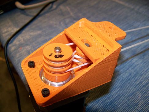
Excellent suggestion, and a very clever system. I took a stab at implementing this, and found that the friction in the system was too high to give good performance. I'm sure it works very well at full scale, but I do not have the space to run the angled pulley on bearings, so I used brass bushings on a dowel pin. It spun freely by hand but I think when load is applied it binds up a little and the capstan affect rears its head to bite me. The very small amount of runout (0.003") on the diameters of the pulleys is also a problem, and I do not have a lathe to true them up.
I've attached a picture of my implementation. I tried it with and without the cable crossing over itself (theoretically it gives more traction since the angle over which it is on the capstan is greater), which was completely unworkable. Without the crossover it worked slightly better (I could move it by hand) but still not good enough.
|
Re: HBot using fishing line February 21, 2013 12:34PM |
Registered: 11 years ago Posts: 15 |
|
Re: HBot using fishing line February 21, 2013 05:46PM |
Admin Registered: 17 years ago Posts: 7,879 |
If you put 608 bearings together the chamfer makes a grooved pulley. Not sure if it would be deep enough. Or you can get grooved 608s and stack them.
[www.hydraraptor.blogspot.com]
[www.hydraraptor.blogspot.com]
|
Re: HBot using fishing line February 22, 2013 02:05AM |
Admin Registered: 16 years ago Posts: 13,884 |
... for feeding thin steel wires in a laserplotter I used nylon coated bearings, where I've lathed a groove in the nylon ring - worked perfect!
With thinner wires than showed (I've used 0.5mm and 0.3mm steel wires) you can cut 3 to 4 grooves, so two bearings will be enough ...
Viktor
--------
Aufruf zum Projekt "Müll-freie Meere" - [reprap.org] -- Deutsche Facebook-Gruppe - [www.facebook.com]
Call for the project "garbage-free seas" - [reprap.org]
|
Re: HBot using fishing line February 22, 2013 02:16AM |
Registered: 13 years ago Posts: 486 |
Could the skewing affect that you have mentioned be fixed by running a second wire around the bot that travels in the opposite direction? Just attach the opposite wire that runs along the x axis to the carriage and wind it on the motors the opposite way.
Edited 1 time(s). Last edit at 02/22/2013 02:18AM by Greg Frost.
Edited 1 time(s). Last edit at 02/22/2013 02:18AM by Greg Frost.
|
Re: HBot using fishing line February 22, 2013 09:16AM |
Registered: 11 years ago Posts: 973 |
Just a question about the bot if I made the frame shorter so the bed stays static and just have the head move up and down instead my aim to make a milling machine im after a maxium bed size figure out a way to cut 6mm material maybe heading too high to wish for a bot like yours by changing the axis from the bed to to the head would cope in milling 6mm aluminium but could do plastics and wood any thoughts
|
Re: HBot using fishing line February 22, 2013 12:01PM |
Registered: 11 years ago Posts: 939 |
Greg Frost Wrote:
-------------------------------------------------------
> Could the skewing affect that you have mentioned
> be fixed by running a second wire around the bot
> that travels in the opposite direction? Just
> attach the opposite wire that runs along the x
> axis to the carriage and wind it on the motors the
> opposite way.
I think it's caused by difference in the length of line from the pulling corner on one side of the carriage to the pulling corner on the other side of the carriage.
The shorter length effectively pulls first causes the carriage to skew slightly, as it skew the friction increases and it's relieved when the other side takes up the "slack" (and I use the term loosely.
In practice for moves along the outside rails this is not significant, but for a move across the carriage it causes the head to wonder slightly.
I've been considering this and I think mounting the motors as close to the carriage as possible, in opposite corners would minimize the effect, it effectively halves the longest run of none driven line, reducing the length of the wire or belt run would also help (i.e. scaling it down). overall rigidity is also important.
I keep meaning to build a 4th prototype, but I'm in 2 minds as to whether coupling both axis together like this is actually a good idea, when there are alternative belt/line configurations that wouldn't need it.
|
Re: HBot using fishing line February 22, 2013 10:32PM |
Registered: 13 years ago Posts: 486 |
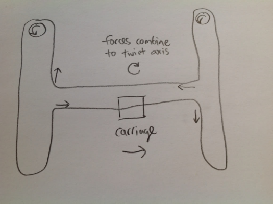
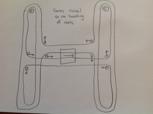
I thought the twisting was because when moving the carriage in x, you need both motors pulling. One pulls one end of the x axis in + y and the other pulls the
end of the x axis in -y. Any play in the linear guides that mount the x axis will result in the axis moving slightly out of perpendicular.
I was trying to visualize a belt path that went the other way around the machine so that both ends of the x axis were pulled in +and - y at the same time.
The pictures below show what I am talking about. Unfortunately I don't think the configuration that I have show will move the axis in the y direction.
|
Re: HBot using fishing line February 25, 2013 10:22AM |
Registered: 11 years ago Posts: 251 |
@Greg, yes I agree that will only move in one axis, but it got me thinking.
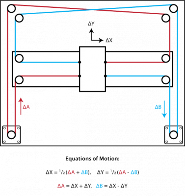
I have a proposal that I believe will have superior performance. This design is actually 2 separate loops of belt, although in principal is not that different to an H bot. I realised after drawing that it would be more elegant to left-right flip one of the loops, but the principal is the same!
I have a proposal that I believe will have superior performance. This design is actually 2 separate loops of belt, although in principal is not that different to an H bot. I realised after drawing that it would be more elegant to left-right flip one of the loops, but the principal is the same!
|
Re: HBot using fishing line February 25, 2013 11:17AM |
Registered: 11 years ago Posts: 251 |
|
Re: HBot using fishing line February 25, 2013 11:27AM |
Registered: 11 years ago Posts: 374 |
@konwiddak
[www.corexy.com]
Did you just derive COREXY's cable layout independently? :-P
Edited 1 time(s). Last edit at 02/25/2013 11:29AM by crispy1.
[www.corexy.com]
Did you just derive COREXY's cable layout independently? :-P
Edited 1 time(s). Last edit at 02/25/2013 11:29AM by crispy1.
|
Re: HBot using fishing line February 25, 2013 11:55AM |
Registered: 11 years ago Posts: 251 |
|
Re: HBot using fishing line February 25, 2013 01:43PM |
I am try to come up with a 100' by 10' to 25' gantry system for an open source urban farming project.
Anyone know of a drive pulley that will get decent friction on a branded wire cable?
I expect a payload from 10 to 50 lbs. Ideally I would like to run several cross rails at once to carry cooperating robots (ie. one to harvest/plant and one to hold and transport).
I thought a cable system might be simplest. I tried a double rail along the long axis and it wanted to skew and bind. Now I am trying a single drive rail down the middle with cable guides on each side. By having the robot centered when traveling lenghtwise I hope it will work.
I am hoping to put the motors and micro controllers at the pay load and not the ends of the gantry, so as to reuce the number of microcontrolers batteries and wireless modules.
Any design sujestion would be apprieciated. we are hoping to use cheap power wheel type DC motor on the long run with limit switchwitch that will detect the hydroponic gulleys and either a stepper motor or a DC moter and some simple image edge filtering to detect plant positions in the gulleys.
Desinging a cheap viable and durable gantry system is harder then I first thougth.
|
Re: HBot using fishing line February 25, 2013 02:53PM |
Registered: 12 years ago Posts: 18 |
There is a old school method of squaring a gantry to the unit via high tension cables. It's light and effective and is independent of the drive mechanism.
[www.cnczone.com]
[www.cnczone.com]
Sorry, only registered users may post in this forum.
