Metal-print Reprap
Posted by Simba
|
Re: Metal-print Reprap January 29, 2013 11:15AM |
Registered: 11 years ago Posts: 24 |
All of what bobc says is correct, but there's one key point he has not covered in detail. Patents protect the inventor by preventing other people from profiting off of the inventor's ideas. If I want to make a 3d printer for my own pleasure, and build objects that I don't sell, I can use any proprietary design I want, copy stuff directly out of someone else's patent or product, etc. But as soon as I make one cent off of the item, they can sue me. In practice, if the user makes less money than the cost of filing the suit, it's economically cheaper to let it slide - suing will end up costing the patent holder money.
Open source is a great way to get around patent issues. And if one is not interested in making a lot of money, one doesn't need to worry about patents. Demonstrating prior art is not that difficult - the guts of a inkjet printer use plenty of the concepts in a 3D printer, and as such are not readily patentable.
Further, one can file patents pretty cheaply. They are much stronger if a patent attorney puts the application together, but also much more expensive. So there's a whole spectrum of costs and benefits.
One final quibble with bobc's post. He writes "It is also quite easy for a patent lawyer to create novel additions to a public idea which essentially wrap the public idea in a patented version." This is true, but it is also easy for a good patent lawyer to get a patent like that invalidated. It does take some time, but eventually it would be sorted out. There are a lot of stupid patents on the books; as long as no one is blocked from making money by them, they just sit there. But when one is questioned, usually it gets blown up, or there is a settlement out of court. A lot of patent trolls do just that - file stupid crazy patents all over the place, and then look for violations. When they find one, they offer to settle for less than it would cost to invalidate the patent, so usually companies settle. And the troll can settle with every company that uses the "patented" techniques. An unfortunate side effect of a reasonable but inperfect system.
In the long run, the system works out, if you can pay a decent patent lawyer. In the short run, anything goes. And over really long time scales, patents expire and ideas become common property of everyone.
Take home message - if you invent an incremental improvement in 3d printing, it is hard to profit off of it, but not impossible. I'd look to consulting with manufacturers of printers over patents and legal fights. If you invent something radical and game changing, get yourself a good patent lawyer and hope for the best. But those are few and far between, and inventors are often not unbiased about their work.
Regards,
aeronaut
|
Re: Metal-print Reprap January 30, 2013 02:49AM |
Registered: 13 years ago Posts: 177 |
It is also a consequence of open source hardware over software.
Software is effectively free to copy or the cost is so small its irrelevant. This makes it very easy to proliferate and free for anyone wishing to acquire it.
Open source hardware requires matirials and manufacturing. It makes proliferation difficult without some businesses set up to sell large numbers of the parts or complete items. It also makes proliferation necessarily costly for someone wishing to acquire the technology.
The reason I could foresee trouble is unlike the software where there is little to no money to be made out of an existing item being proliferated. Hardware necessarily has a market. And money attracts attention.
Make your Mendel twice as accurate.
[www.thingiverse.com]
|
Re: Metal-print Reprap February 02, 2013 12:47PM |
Registered: 11 years ago Posts: 177 |
I was wondering if anyone has considered wire or powdered ferrous material being released through a nozzle surrounded by an induction coil on to a ceramic build platform. Under the platform would be an electromagnet shadowing the movements of the nozzle overhead and keeping the metal above in shape until it cools.
Edited 1 time(s). Last edit at 02/02/2013 12:52PM by Evil Monkey.
Edited 1 time(s). Last edit at 02/02/2013 12:52PM by Evil Monkey.
|
Re: Metal-print Reprap February 10, 2013 11:41AM |
Registered: 11 years ago Posts: 4 |
I had this idea some time back, but just an idea and I have no clue whether any of it is useable....
Standard molten metal working uses crucibles made from Fireclay.
Use standard RepRap with clay extruder, currently used for porcelein, but fill with Fireclay slip.
Print hot end, may need to print 2 halves, join together after with slip and copper wire to form final hole.
Wrap with heater wire, covering each layer with more Fireclay slip.
Fire hot end.
This could give a hot end that would handle any molten metal.
Already covered extruder hole (copper wire).
Metal entry: top end has inner channel to allow metal input as wire, then chamber, then outer skin. Channel has holes, water or air or oil fed through channel to give realtively cold top end for mounting.
If it worked the you would have RepRap created hot end that could handle any material.
But I have no idea if any of it is at all workable.
|
Re: Metal-print Reprap March 22, 2013 11:12AM |
Registered: 11 years ago Posts: 482 |
Evil Monkey Wrote:
-------------------------------------------------------
> I was wondering if anyone has considered wire or
> powdered ferrous material being released through a
> nozzle surrounded by an induction coil on to a
> ceramic build platform. Under the platform would
> be an electromagnet shadowing the movements of the
> nozzle overhead and keeping the metal above in
> shape until it cools.
I have.
However, every simulation I have done indicates that the metal or ceramic underneath the nozzle would wick away heat SO fast that it would not stick properly. On the other hand, stainless steel is dense and has a lower thermal conductivity than nearly all metals - for this reason it may work, but even high grades of stainless would oxidize about 600C, incaloy ~700C, so no matter what we need an inert environment I think.
|
Re: Metal-print Reprap August 26, 2013 06:49AM |
Registered: 12 years ago Posts: 80 |
Like I mentioned on the Wax Printer thread that moved from a multi jet Phasor head to a paste extruder with a twist described below.
Wax and metal do not have a convenient plastic melting phase like plastics. They liquefy. Now if you had a support material that would keep the liquid material in place then you could print with these materials.
There are various 'salts' that are used in industry in a molten state. A famous one is the salt electrolyte in the refining of Aluminium. Others are used to heat treat metals. Some solar thermal power stations used molten salts to store energy overnight.
What if one were to have your build platform in a tank that was filled with a molten salt. Now imagine the salt has a similar density to the metal you are extruding. When it exits the nozzle it displaces salt and bonds with the metal below and the buoyancy of the salt prevents it from running down the sides before it solidifies. A extra bonus could be that the salt might be a suitable flux (oxide remover) or otherwise enhance the metal to metal bonding.
One could also use a powered flux instead of a molten salt. This is used in some contiguous wire feed arc welders that do not use inert shielding gas but use a powder that completely covers the submerged arc. This allows for low resolution deposition of real metals by computer control, not very accurate but perhaps could replace castings that are to be machined later.
The build platform could be any suitable material that will stick to the metal that can be selectively etched away.
My other thought is to use ultrasonic bonding of wire like IC die bonding wires or laser bonding of wire like injection mould repair methods. This has been discussed before as well and the ultrasonic bonding of metal foil is a existing technology but requires a big machine.
[forums.reprap.org]
[forums.reprap.org]
With the wax printer the choice of materials could be inspired by a lava lamp where the wax likes the wax but not the liquid and they have similar densities.
[forums.reprap.org]
Kalle
--
Lahti, Finland
The only stable form of government is Open Source Government. - Kalle Pihlajasaari 2013
|
Re: Metal-print Reprap December 02, 2013 02:07PM |
Registered: 11 years ago Posts: 41 |
Hi,
I've been reading about metal 3d printing today in the forums.
and that ceramic might be the key to 3d metal printing. I've been reading a little about this the last couple of days. it seems that aluminium has a melting point of ~660 degrees Celcius.
i was looking at ordering 1.6mm 100% aluminium welding wire to give my new hotend a try, its make from zirconia ceramic, and industrial ceramic used in various industries
http://www.youtube.com/watch?v=xJO8MrfUdI0
the orfice size is 0.4mm, i wonder how hard it would be to push 1.6mm aluminium through a 0.4mm orfice
I've cranked it up to 300C with the current heater cartridet(12V, 10A power supply), i am sure i can crank it up to 450C(mauk
If i would would use 2 heater cartridges, how easy would it be to go 650C? and then starting to extrude aluminium wouldn't that be something.
hp_
|
Re: Metal-print Reprap December 02, 2013 02:22PM |
Admin Registered: 16 years ago Posts: 13,884 |
... for aluminium you'll need an inert gas for shielding against oxidisation ... and when melted, it behaves not viscous like plastic, it will got fluid -- so the extruding parameters should differ drastically from printing with plastics ...
Viktor
--------
Aufruf zum Projekt "Müll-freie Meere" - [reprap.org] -- Deutsche Facebook-Gruppe - [www.facebook.com]
Call for the project "garbage-free seas" - [reprap.org]
Viktor
--------
Aufruf zum Projekt "Müll-freie Meere" - [reprap.org] -- Deutsche Facebook-Gruppe - [www.facebook.com]
Call for the project "garbage-free seas" - [reprap.org]
|
Re: Metal-print Reprap December 02, 2013 02:26PM |
Registered: 11 years ago Posts: 41 |
|
Re: Metal-print Reprap December 02, 2013 03:02PM |
Registered: 10 years ago Posts: 1,381 |
Oxidation will prevent bonding.
Cool zirconia nozzle, is there plans to sell it?
[www.youtube.com]
[www.youtube.com]
I have a few Coors zirconia parts that are precursors to a ceramic bearing.
I've thrown it at the pavement repeatably and it's as strong as steel, pavement chips.
F1 uses the same material for the valves.
Cool zirconia nozzle, is there plans to sell it?
[www.youtube.com]
[www.youtube.com]
I have a few Coors zirconia parts that are precursors to a ceramic bearing.
I've thrown it at the pavement repeatably and it's as strong as steel, pavement chips.
F1 uses the same material for the valves.
|
Re: Metal-print Reprap December 02, 2013 03:42PM |
Registered: 11 years ago Posts: 41 |
A2 thanks for the information on oxidation,
Yeah you are right about the material properties of this ceramic
the reason i chose zirconia was its thermal conductivity, which is low and heat resistance:
[3.bp.blogspot.com]
we are currently testing the hotend, we have 10 pieces now, but planning to have more when there is enough interest
hp_
Yeah you are right about the material properties of this ceramic
the reason i chose zirconia was its thermal conductivity, which is low and heat resistance:
[3.bp.blogspot.com]
we are currently testing the hotend, we have 10 pieces now, but planning to have more when there is enough interest
hp_
|
Re: Metal-print Reprap December 02, 2013 11:45PM |
Registered: 10 years ago Posts: 1,381 |
Disclaimer: This post does not constitute legal advice. I am not an attorney.
I do not have expertise in these matters.
I discourage everyone from trying this.
@ Hp_
3D Plastic Printer:
I missed that the hot end was your creation, it looks great.
I want one of your nozzles for plastic filament testing, how do you prefer to be paid?
I was originally attracted to zirconia as an insulator for a production plastic fusion welding machine.
The reason I'm studying 3D plastic printers is to help further my R&D efforts of a liquid metal printer.
Filament printing takes less funds, and there is a lot for me to learn about the software that controls the equipment.
3D Liquid Metal Printer:
I have designs for a 3D metal printer, but development is on hold at the moment, because I don't have the funds to support a rigors r&d effort, but I'm still adding too it when the opportunity presents.
I have designed a new type of crucible to manage the main problems associated with liquid metal printing,
and one that can be manufactured at a significant cost savings.
Not having the funds to make the many prototypes required, I'm unable to verify my designs.
I have 3 or 4 parts that could benefit from being manufactured from zirconia, the most obvious being the nozzle.
Ceramic doesn't solve all manufacturing issues associated with printing liquid metal. Unless you have new idea for it?
But ceramic is useful for its wear, non-wetting, insulative, high heat tolerance, and strength properties.
Die steel works fine too, and at a reduced cost, unless the price of zirconia has come down?.
There are components that would benefit being manufactured from zirconia if the price was right.
Liquid aluminum would drip through a 0.4 mm (0.016 inch) orifice.
200 μm (0.008 inch) inhibits undesired leakage of liquid aluminum, as a capillary action occurs,
it also depends on the length of the orifice land.
For liquid aluminum droplet deposition the nozzle orifice diameter is around 0.3mm (0.012 inch), a vacuum is typically used to prevent leakage.
Tin/solder, nozzles 0.076–0.254 mm in diameter, (.003-.010 inch).
It's not possible to place liquid metal into a neat row like a plastic filament, it won't work. It's akin to tying to place liquid water into a straight line.
The pressure required depends on a lot of factors, but for liquid aluminum the pressure is negligible, as it flows like water when melted.
You would also need a temperature controlled enclosure filled with argon gas.
Basically the chamber would require a vacuum to excavate the air,
then fill it with argon gas, the oxygen content needs to be really low for reliable fusion.
The aluminum feed stock needs to be extremely clean.
There are many other factors that can prevent printing with liquid metal,
that's why you don't see it any where but in the labs.
Depending on the technique and equipment, a home 3d liquid metal printer most likely would be very slow,
and just one mistake would force you to start the time consuming process over.
It would take many hours to recover from any kind of mistake.
All that said, I wouldn't go so far to say that you couldn't get a DIY version to work with less than ideal conditions.
If you are not a safety minded person, you don't own safety equipment, have a second person overlooking you, and to take you to the hospital in case of an accident, and have the expertise to test liquid streams of aluminum, and more
you shouldn't even consider purchasing the aluminum wire, and higher temp cartridge heater.
I encourage you or any one else reading this not to test this.
The zirconia nozzle would make for an interesting experiment.
It would best to view it with a remote camera.
Caution/warning, and this is serious, you can easily maim or kill your self with a tiny stream of liquid aluminum,
I think there is a neurological disease as well.
Take every safety precaution that is necessary. As a reminder of how dangerous a tiny stream of liquid aluminum is,
I have a small collection of pictures of maimed human body parts (mostly hands and arms) caused by tiny streams of liquid aluminum,
if you would like to see the pictures I will post them. I seriously can't look at them, they are very disgusting.
It's surprising what a tiny stream of liquid aluminum can do to human flesh.
I have some experience with spray coating liquid aluminum to build up worn shafts, but not with 3d metal printing.
Ejecting liquid metal from an orifice is dangerous.
I discourage everyone from trying this.
A2
Edited 2 time(s). Last edit at 12/03/2013 09:58AM by A2.
I do not have expertise in these matters.
I discourage everyone from trying this.

@ Hp_
3D Plastic Printer:
I missed that the hot end was your creation, it looks great.
I want one of your nozzles for plastic filament testing, how do you prefer to be paid?
I was originally attracted to zirconia as an insulator for a production plastic fusion welding machine.
The reason I'm studying 3D plastic printers is to help further my R&D efforts of a liquid metal printer.
Filament printing takes less funds, and there is a lot for me to learn about the software that controls the equipment.
3D Liquid Metal Printer:
I have designs for a 3D metal printer, but development is on hold at the moment, because I don't have the funds to support a rigors r&d effort, but I'm still adding too it when the opportunity presents.
I have designed a new type of crucible to manage the main problems associated with liquid metal printing,
and one that can be manufactured at a significant cost savings.
Not having the funds to make the many prototypes required, I'm unable to verify my designs.
I have 3 or 4 parts that could benefit from being manufactured from zirconia, the most obvious being the nozzle.
Quote
Hp_
“...ceramic might be the key to 3d metal printing“
“...aluminium has a melting point of ~660 degrees Celcius.“
Ceramic doesn't solve all manufacturing issues associated with printing liquid metal. Unless you have new idea for it?
But ceramic is useful for its wear, non-wetting, insulative, high heat tolerance, and strength properties.
Die steel works fine too, and at a reduced cost, unless the price of zirconia has come down?.
There are components that would benefit being manufactured from zirconia if the price was right.
Quote
Hp_
“...how hard it would be to push 1.6mm aluminium through a 0.4mm orfice.”
Liquid aluminum would drip through a 0.4 mm (0.016 inch) orifice.
200 μm (0.008 inch) inhibits undesired leakage of liquid aluminum, as a capillary action occurs,
it also depends on the length of the orifice land.
For liquid aluminum droplet deposition the nozzle orifice diameter is around 0.3mm (0.012 inch), a vacuum is typically used to prevent leakage.
Tin/solder, nozzles 0.076–0.254 mm in diameter, (.003-.010 inch).
It's not possible to place liquid metal into a neat row like a plastic filament, it won't work. It's akin to tying to place liquid water into a straight line.
The pressure required depends on a lot of factors, but for liquid aluminum the pressure is negligible, as it flows like water when melted.
You would also need a temperature controlled enclosure filled with argon gas.
Basically the chamber would require a vacuum to excavate the air,
then fill it with argon gas, the oxygen content needs to be really low for reliable fusion.
The aluminum feed stock needs to be extremely clean.
There are many other factors that can prevent printing with liquid metal,
that's why you don't see it any where but in the labs.
Depending on the technique and equipment, a home 3d liquid metal printer most likely would be very slow,
and just one mistake would force you to start the time consuming process over.
It would take many hours to recover from any kind of mistake.
All that said, I wouldn't go so far to say that you couldn't get a DIY version to work with less than ideal conditions.
If you are not a safety minded person, you don't own safety equipment, have a second person overlooking you, and to take you to the hospital in case of an accident, and have the expertise to test liquid streams of aluminum, and more
you shouldn't even consider purchasing the aluminum wire, and higher temp cartridge heater.
I encourage you or any one else reading this not to test this.
The zirconia nozzle would make for an interesting experiment.
It would best to view it with a remote camera.
Caution/warning, and this is serious, you can easily maim or kill your self with a tiny stream of liquid aluminum,
I think there is a neurological disease as well.
Take every safety precaution that is necessary. As a reminder of how dangerous a tiny stream of liquid aluminum is,
I have a small collection of pictures of maimed human body parts (mostly hands and arms) caused by tiny streams of liquid aluminum,
if you would like to see the pictures I will post them. I seriously can't look at them, they are very disgusting.
It's surprising what a tiny stream of liquid aluminum can do to human flesh.
I have some experience with spray coating liquid aluminum to build up worn shafts, but not with 3d metal printing.
Ejecting liquid metal from an orifice is dangerous.
I discourage everyone from trying this.
A2
Edited 2 time(s). Last edit at 12/03/2013 09:58AM by A2.
|
Re: Metal-print Reprap December 03, 2013 06:24PM |
Registered: 10 years ago Posts: 1 |
|
Re: Metal-print Reprap December 05, 2013 06:45AM |
Registered: 11 years ago Posts: 74 |
You might want to warn "Vader Systems" of these dangers! [www.metalbot.org]
They are using magnetism to fire the droplets down onto the build platform. However I don't see any implementation of an inert atmosphere...
Vader Systems
Edited 1 time(s). Last edit at 12/05/2013 06:45AM by Hazel1919.
3D Metal Printing and more - visit [www.metalbot.org] !
They are using magnetism to fire the droplets down onto the build platform. However I don't see any implementation of an inert atmosphere...
Vader Systems
Edited 1 time(s). Last edit at 12/05/2013 06:45AM by Hazel1919.
3D Metal Printing and more - visit [www.metalbot.org] !
|
Re: Metal-print Reprap December 05, 2013 11:01AM |
Registered: 10 years ago Posts: 1,381 |

I've recently became aware of Vader announcement to enter the 3d metal droplet deposition arena.
Vader pricing is in the ballpark of what I figured a consumer version could sell for today, under $10,000.
Initially Vader mentioned that they were going to target the consumer market,
but now it sounds like they will be focusing only on BtoB sales?
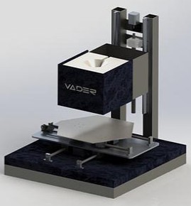
Here is a video of Vader talking about his 3d metal printer.
It's not shown running, it's not shown with a droplet generator mounted,
it's not shown with all the supporting equipment, nor have they shown any prototype parts:
[www.youtube.com]
Vader is not showing all of the equipment required to make it operational,
maybe they have something propitiatory in the works?
Vader has a phD, so maybe he has a few innovations that he wants to protect?
I can only imagine that today it looks like a RepRap hack
Vader is using magnetohydrodynamics to generate a droplet.
It's been done before, and It's one of the technologies that I want to explore, it's also got the cool factor, well if your a geek
I'm very curious to learn how Vader crucible is constructed.
They plan to have their first sales in 2015, if I recall correctly a few 3d metal droplet patents will be expiring,
is Vader capitalizing on expired I.P.?
[www.vadersystems.com]
Generating a droplet has been demonstrated with many different technologies,
what is massively difficult is avoiding all the I.P. that covers droplet generators,
it's almost completely locked up. If they did copy an existing unprotected (patent expired) droplet generator design
then in my opinion it will be a real PITA to run, regardless any metal droplet generator will be a PITA run,
but some of the operational difficulties can be reduced.
I think the most promising droplet generator design is the StarJet, as it's a cheap replaceable consumable.
The tiny orifice will become clogged. In my opinion no other orifice solves the problem of a clogged nozzle as well as the StarJet design.
Simply remove it and replace it with a new one.
If Vader has a licencing agreement with StarJet then they have gone a long way to securing a successful product.
You could try to purchase a StarJet orifice from them for your own use, which I don't recommend because it's dangerous if you don't know what you're doing.
I find this announcement exciting, I hope Vader is successfully, as it will either validate some of my ideas, or help me to move on to a different project.
Edited 1 time(s). Last edit at 12/05/2013 11:01AM by A2.
|
Re: Metal-print Reprap December 19, 2013 05:24PM |
Registered: 10 years ago Posts: 439 |
|
Re: Metal-print Reprap December 19, 2013 06:40PM |
Registered: 10 years ago Posts: 1,381 |
It would be nearly the same amount of time, effort, and money that you would have to put into developing
a solder metal printer (i.e. tin) as it would be for an aluminum metal printer.
In the coming years some metal patents expire, and there are still unexplored techniques to be tested.
Vader knows this, that is why he is working on it.
I expect more mom & pop metal printer companies in the near future.
There is enough free information published on how make a metal printer that you can build a home metal printer today.
I'm curious how much venture capital money will be thrown at Vader?
All one needs is time, effort, creativity, and money, and metal printing can be realized today, at home.
I'm missing the money component to pull it off, or I would create an open source metal printer.
A lot of R&D has to be done to make it work.
R&D = reverse engineer and duplicate.
|
Re: Metal-print Reprap December 21, 2013 06:34AM |
Registered: 11 years ago Posts: 6 |
Hello my friends. I think this is a big step in metal printing. What do you think? [www.3ders.org]
|
Re: Metal-print Reprap December 21, 2013 11:38AM |
Registered: 11 years ago Posts: 246 |
Quote
Spyrakos
Hello my friends. I think this is a big step in metal printing. What do you think? [www.3ders.org]
Wow! That looks incredible! It seems MUCH more manageable than hot metal extrusion. I just wish they would give more info about their metal clay mixture.
Eric
|
Re: Metal-print Reprap December 21, 2013 08:02PM |
Registered: 10 years ago Posts: 1,381 |
@Spyrakos,
Polymer based metals is not new, it's been around since the 1980's.
The main challenges are porosity, the homogeneity mixing of dissimilar metals, and shrinking.
What they did not show is a "100% solid steel" object, steel is whole another animal to form as a solid.
Typically you will find porous steel objects infused with a soft metal to make it a solid.
@RP Iron Man
You can purchase powdered metal, and mix it with a binder to extrude it.
Binding agents used for MIM, sintering, HIP:
Wax, debind with thermal or Solvent.
PVA, debind with water.
Water+Agar, debind with: evaporation.
Polyacetal (Delrin, Acetal), debind with Nitric Acid.
If you want to make your own metal powder 2 ways:
Spray with water or nitrogen at a liquid stream of metal.
(Extremely dangerous, don't attempt if you don't fully comprehend EVERYTHING about this process).
Mechanical, ball mill, etc.
(Don't breath the dust, it will kill you).
I plan to make a Moineau pump for ceramic extrusion, it would work well for this application.
Moineau stepper extruder
[forums.reprap.org]
MIM (metal injection molding).
[en.wikipedia.org]
Metal powder and powder metallurgy technology
[www.youtube.com]
Metal Injection Moulding (MIM)
[www.youtube.com]
And it's been used in adornment manufacture.
[www.bronzclay.com]
Metal Injection Molding (MIM) Process and Production
[www.dshtech.com]
Powder Injection Molding of Metal and Ceramic Parts
[www.intechopen.com]
Powder Injection Molding of Metal and Ceramic Parts
3.1 Binder formulation
Binder vehicles used for PIM are usually designed as multi-component systems. One of the main components is termed backbone, which is a thermoplastic polymer that supports and maintains the shape of the molded part until the last stages of debinding (Thomas-Vielma et al, 2008). As examples of currently used backbones, it is possible to mention ethylene vinyl acetate (EVA), polyethylene (PE), polypropylene (PP), polystyrene (PS), polyethylene glycol (PEG), polymethyl methacrylate (PMMA) among others (Ahn et al, 2009; Chuankrerkkul et al, 2007; Krug et al, 2002; Thomas-Vielma et al 2008; Yang et al, 2002) (Fig. 5).
The second component, usually in a proportion similar to the backbone is commonly a wax, as paraffin or carnauba wax, or in some cases even agarose, that improves the material flowability (Ahn et al, 2009). Besides improving flowability, such component should be easily removed in early stages of debinding, in general via solvent methods, leaving open pores that will allow the gaseous products of the remaining polymer to diffuse out of the structure (Thomas-Vielma et al, 2008). Even though this low-melting temperature component has an important role in the process, it is worth to mention that the mechanical integrity of the final product is reduced as its proportion increase after certain limits (Tseng & Hsu, 1999).
One of the most important properties of the feedstock is certainly its homogeneity. A homogeneous distribution of powder particles and binder in feedstock is important as it helps to minimize segregation during the injection molding stage and later on to obtain isotropic shrinkage after debinding and sintering (Quinard et al, 2009). Avoiding segregation of feedstock components is necessary to prevent visual defects, excessive porosity, warpage and cracks in the sintered part (Thornagel, 2010).
However, the emergence of a POM-based binder system for PIM has made it possible to remove the polymer vehicle from up to 35 mm thick sections without the use of any wax or low molecular weight component (Krug et al, 2000). As previously described, POM (Fig.5) decomposes predominantly to formaldehyde in the presence of an acid vapor (as oxalic or nitric acid) well below its softening point, that is, in the solid state, avoiding the cracks and bloating that can be caused by the boiling of the binder (Krug et al, 2001). It is also important to mention that the polymer is not penetrated by the gaseous acid and the decomposition proceeds exclusively at the gas-binder interface with a nearly planar debinding front moving through the compact. In this sense, gas exchange is limited to the already porous shell and the buildup of an internal pressure is avoided. Nevertheless, POM-based binder systems often contains up to 30% of polyethylene which does not react with acid vapors, acting as a backbone until being burned out during the sintering cycle.
Finally, additives as surfactants can compose the binder, being stearic acid the most common example of them. These surface-active dispersants normally present a low melting temperature and affinity to preferentially adsorb onto powder surfaces, forming a densely thin outer layer on a particle surface which leads to a more homogeneous packing structure (Chan & Lin, 1995). However, bubbles and cracks were reported to occur as the amount of the surfactants increases, presumably owning to the reduced vaporization temp
[www.intechopen.com]
Edited 3 time(s). Last edit at 12/22/2013 10:06AM by A2.
|
Re: Metal-print Reprap December 22, 2013 05:16AM |
Registered: 10 years ago Posts: 17 |
One of my friends did his master's project on a similar design at Hod Lipson's lab at Cornell. I don't know about the specifics but he told me they were having trouble in terms of material property. You can find more about his research at [creativemachines.cornell.edu]
|
Re: Metal-print Reprap December 22, 2013 10:25AM |
Registered: 10 years ago Posts: 1,381 |

@zoroeye ,
Tks for pointing out your friends paper!
I read this paper before.
They mention that this is a new process, I wonder if that means that
they were the first to 3d metal print with a slurry, Aug 2008!

Lobovsky M., Lobovsky A., Behi M., Lipson H. (2008),
"Solid Freeform Fabrication of Stainless Steel Using Fab@Home",
Proceedings of the 19th Annual Solid Freeform Fabrication Symposium, Austin TX, Aug 2008.
[creativemachines.cornell.edu]
Solid Freeform Fabrication of Stainless Steel Using Fab@Home
Maxim Lobovsky1
, Alexander Lobovsky2
, Mohammad Behi2
, and Hod Lipson1
1Cornell University, Ithaca, NY
2United Materials Technologies, LLC, Westfield, NJ
[creativemachines.cornell.edu]
Feedstock Preparation
The feedstock was prepared at United Materials Technologies, LLC in a proprietary process.
It contains 45-55% by volume of 17-4 PH powder with a mean size of 12μm, a polysaccharide
binder, silicate or borate compounds and water. The materials are combined in a high-shear mixer at
90°C and mixed for about 30 minutes. Extra care is also taken to prevent air from being stirred into
the mixture as this negatively affects print quality and final part density. The feedstock becomes
liquid at approximately 85°C and is a wet, clay-like solid at room temperature. Finally, it is cooled
and pelletized.
The pellets are loaded into a 10cc syringe and compressed to remove air. The syringe is
heated to liquefy the feedstock. We attempted several different techniques to remove the air
including letting the syringe sit for extended periods and vibrating. Both of these techniques are not
effective because the slurry is too viscous for bubbles to travel.
Two effective techniques for air removal that were tried include centrifuging and brief
exposure to vacuum. Centrifuging is somewhat effective but is limited because extended
centrifuging at high g-forces causes the slurry to separate. An effective centrifuging program was 3
minutes at about 1000 g force.
Another effective method is to extrude the feedstock from the syringe into an open container
while the container is under vacuum. This causes bubbles of gas to expand and burst out of the bead
of slurry that is created. The slurry cannot sustain extended exposure to low pressure as the water
will boil out changing the composition of the slurry.
Printing
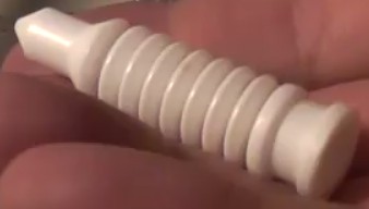
The Fab@Home, shown in Figure 1, with a mount for a custom-built syringe heater was used
to print the slurry. The standard Fab@Home software was used for machine control and path
planning. A 22 gauge (0.016 in diameter) tapered plastic nozzle from EFD, Inc. was used for all of
the example parts shown it is possible to print through smaller nozzles. The syringe is loaded into a
custom built heater with thermocouple and mounted in the Fab@Home. Several geometries were
attempted including thin walls, tensile-test bars, gears, and parts with small lettering.
Sintering
Before the green part can be sintered, a large fraction of the water must be removed to
prevent outgassing during rapid temperature ramping. This can be done at room temperature in ~24
hours or in an oven or under heat gun at ~80°C for about 30 minutes.
After the parts are dried, they are placed in a furnace boat and loaded into a controlled
atmosphere furnace. In our process, we used a 1.5 in. I.D. tube furnace with a single ~8 in. hot zone.
The furnace is capped and a flow of reducing atmosphere is applied.
A typical heating schedule consists of two main steps. First a 1.5 hr ramp to 550°C followed
by a 1 hr hold. This is called the debinding step and it allows all for the majority of the binder to be
burned out while the part is still porous. Debinding often takes place in a different oven under a
different atmosphere than that required by sintering, but this slurry has a very small binder content
so a simple debinding step is possible.
Next, in the main sintering step the furnace is ramped for 1.5 hr to 1350-1400°C and held for
1 hr then allowed to cool. The peak sintering temperature was varied to find the maximum density
(as described in the section Shrinkage and Density below) without significant deformation to the
geometry. This optimum temperature was about 1380°C.
Initially, a 94% nitrogen, 6% hydrogen atmosphere was used, but this created parts with poor
final densities. As suggested in [8], switching to a nitrogen free atmosphere, 94% Argon, 6%
Hydrogen improved densities significantly.
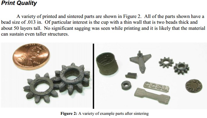
One of the issues encountered while printing is that it is difficult to control starting and
stopping the flow from the syringe with the type of deposition tool used in the Fab@Home. As the
Fab@Home only controls the height of the plunger, compression in the fluid prevents the system
from accurately controlling the amount of fluid leaving the nozzle. Most of this compression is
created by air bubbles in the fluid. Without using centrifuging or vacuum degassing, it is very
difficult to create good quality parts. Even when great care is taken, the flow does not stop very
precisely. This is visible as the small protrusions or holes in the gear or cup seen in Figure 2.
Another issue encountered is warping caused by non-uniform drying of the part. Some
shrinkage occurs while the water evaporates from the part after printing. If the part dries unevenly,
this shrinkage will occur unevenly and the part may warp. Additionally, if the slurry binds to the
substrate, it may prevent the bottom surface from shrinking uniformly. An example of this type of
warping is shown in Figure 3.
Shrinkage and Density
One of the key parameters measured for sintered metal materials is the density of the final
part as many materials properties are strongly and positively correlated with this property. This
process produces gaps within the parts because the bead typically fails to fill the entire volume of the
part. To account for this each sintering run included a part produced by extruding a small lump of
slurry with no gaps was included to measure the density of the solid portion of the part.
Density was measured using Archimedes method. After optimizing the sintering conditions,
a volume fraction density for the solid parts of 94% and a volume fraction for a printed cube was
90%.
Linear shrinkage was measured by taking length measurements with a digital camera within
one minute after finishing printing and after sintering. Note that some shrinkage (1-2%) occurs
during drying after printing so it is important to take measurements before significant drying occurs.
Total linear shrinkage for drying and sintering a printed part was 18%.
These shrinkage and density values are comparable to those for injection-molded stainless
steel [8]. Improved path planning and control of slurry rheology may allow for improvements to the
densities of printed parts.
Tensile Strength
Note that the tensile strength of arbitrary parts is strongly dependent on the path pattern with
which they are printed and the following results should be taken only as an example of typical
strengths of printed parts. Tensile strength was measured on printed and sintered tensile bars with
final dimensions of the gauge area of approximately 0.212 x 0.100 x 0.550 in. printed with a
border/cross-hatch pattern. The bars were strained at a crosshead rate .05 in/min. The measured
tensile strength varied widely and all of the specimens broke at the end of the gauge area suggesting
that poor print quality or path planning created stress concentrations that led to failure. The best
achieved tensile strength was 53000 ksi or 35% of pure 17-4 PH.
As injection-molded stainless steel parts can have tensile strengths of around 80-90% [8] of
pure stainless steel, it is likely that further optimization of the sintering process, and more
importantly, better print quality and path planning can let this process achieve significantly higher
tensile strengths.
Conclusion
A new process for the solid freeform fabrication of steel parts is demonstrated. Example
parts were fabricated with features as small as .32 mm out of 17-4 PH stainless steel. Mechanical
properties are good with printed parts having densities of up to 90% and tensile strength of up to
35% that of the pure metal. This process can be applied with minimal changes to a wide range of
metals, ceramics, composites, and multiple materials in the same part.
Edited 1 time(s). Last edit at 12/22/2013 10:27AM by A2.
|
Re: Metal-print Reprap January 01, 2014 06:05PM |
Registered: 10 years ago Posts: 10 |
Thanks for the article , was thinking to an application of MIM to FDM just like this way.
I thought too that if metal powder could be mixed in proper ratio with pla or abs and keep their same bend resistance at low temperature, it could be possible to print MIM casting from any of the already working RepRaps. Some problem could come with rheology of the molten "slurry" and prolly with the extrusion head wear due to metal particles "sanding" it, but prolly this problems could be solved with a proper extrusor motor adjustment and changing the nozzle with something more wear-resistant (ceramic or heat-treated steel).
Than after obtaining the binded from it could be sintered with a properly arranged microwave oven (looks like microwaves are quite efficient in metal powder sintering, actually much more energy saving han laser sintering). Since the microwave sintering process doesn't require an atmosphere, would be the best to run it in vacuum, because this would reduce heat dispersion by convection and would greatly improve debinding. I even think that with the proper heat radiation insulation this could be done in a home microwave oven, if arranged to work on vacuum.
|
Re: Metal-print Reprap September 01, 2014 04:57AM |
Registered: 9 years ago Posts: 4 |
I just joined to get help with the MIM to FDM and other affordable metal production methods.
For decorative purposes a filament that creates the equivalent cold cast bronze should be fairly straight forward and would possibly have some interesting properties.
Most of my concerns relate to FDM or any of the lower cost powder deposition methods.
Yes particle size and shape play a role, but MIM suppliers are already controlling for that so we can skip that for now.
Beyond that getting metal parts that we would find acceptable will mainly depend on sintering.
Sintering at the home/hobby level will have to be investigated iteratively in my opinion. There is a lot of components to the process and lots of process interactions to be accounted for. This of course also allows for some interesting possibilities in altering the part's properties within the sintering process itself. While I am somewhat familiar with the press/sinter P/M industry only some of that will be transferable to this investigation.
I plan on concentrating initially on one of the bronze alloys. First because as I said above even my misses will have decorative applications and second because oil impregnated bronze bearings/bushings could be used in the RepRap process as one more printed component.
Additionally its sintering temperature (in the Mid 800's C) should allow for a wide range of Sintering furnace types at a relatively low cost. I'll probably start with a Microwave.
I have a lot of things on my plate and will only be working on this as I can. Don't expect rapid developments.
|
Re: Metal-print Reprap October 02, 2014 09:59PM |
Registered: 9 years ago Posts: 127 |
Well, for FFF (classic RepRap style), I don't see how molten metal can be used easily.
But for a powder bed, the first thing that comes to mind is a sand powder bed, with a dual-component head.
The first component is an electro-valve controlled vaccum pipe, that can suck up sand grains.
The second component would be your liquid metal extruder (ie solder flowing into a hollow tip soldering iron, like the design used for solder removal irons)
I would envision printing would follow this process:
If you have an existing powder bed setup, this shouldn't be too hard to prototype, as solder already comes in a spool form.
But for a powder bed, the first thing that comes to mind is a sand powder bed, with a dual-component head.
The first component is an electro-valve controlled vaccum pipe, that can suck up sand grains.
The second component would be your liquid metal extruder (ie solder flowing into a hollow tip soldering iron, like the design used for solder removal irons)
I would envision printing would follow this process:
- Part bed lowers by one Z increment
- Powder feed (fine grain dry sand) bed raises by one Z increment
- Fine sand is rolled from powder feed to part bed
- Vacuum head is selected on X/Y plane, and sand layer is removed in the slice
- Metal pour head is selected on X/Y plane, and pour is performed at selected spots in the slice for fill operations (a bit of tricky math going on here for good spread)
- Go to 1.
If you have an existing powder bed setup, this shouldn't be too hard to prototype, as solder already comes in a spool form.
|
Re: Metal-print Reprap October 02, 2014 11:31PM |
Registered: 9 years ago Posts: 4 |
The basic question for metal and Reprap is are we willing to accept a post print function? If we are then a sintering phase post print could greatly expand the materials available to even the home user.
A microwave kiln can be purchased for less then $100 USD. Metal Clay is sintered at home all the time. Creating even a Filament for FFF is not out of the range of the possible.
A microwave kiln can be purchased for less then $100 USD. Metal Clay is sintered at home all the time. Creating even a Filament for FFF is not out of the range of the possible.
|
Re: Metal-print Reprap November 01, 2014 11:23AM |
Registered: 10 years ago Posts: 1,381 |

Sorry, only registered users may post in this forum.