Full Color 3d Printer Project
Posted by CPS
|
Re: Full Color 3d Printer Project - hot end design May 21, 2013 06:31PM |
Registered: 10 years ago Posts: 580 |
I was inspired by Myles Corbett's research to design a six color, color mixing not end. It could also be used for quick color switching.
Additional images here.
Your kind thoughts are welcome.
My printer: Raptosaur - Large Format Delta - [www.paulwanamaker.wordpress.com]
Can you answer questions about Calibration, Printing issues, Mechanics? Write it up and improve the Wiki!
|
Re: Full Color 3d Printer Project - hot end design May 22, 2013 03:01PM |
Registered: 11 years ago Posts: 44 |
Do you know about how much it would weigh, it seems like it would be heavy,
My idea was almost exactly the same except what you have colored green, and just have plastic tubes feeding in the filament.
I really like your idea about the color switching, but could u do the same thing with just the color mixer, pull back the other 5 colors?
My idea was almost exactly the same except what you have colored green, and just have plastic tubes feeding in the filament.
I really like your idea about the color switching, but could u do the same thing with just the color mixer, pull back the other 5 colors?
|
Re: Full Color 3d Printer Project May 22, 2013 03:41PM |
Registered: 10 years ago Posts: 580 |
CPS,
Its always a good thing to look at how heavy and how complex - it could be made lighter and easier to machine.
It's a bit smaller than it looks - the copper hotend part .812" tall, and 1" diameter at the widest. The stirrer motor would be a lot smaller (I just put on one I had a model of).
As far as the water block is concerned - that could be eliminated by just using a small fan, or made in a different way (I'm still thinking about it). I was considering a water block because I was considering using an enclosed (heated) build chamber.
I would keep the stainless tubes however - for very low thermal conductivity so the Bowden tubes are not softened.
As far as switching/pulling the other filaments - that's something that would need experimenting with, as well as the mixing chamber length, mixer rod diameter, etc.
I'm eager to see what you've done too, dunno if I missed a link.
|
Re: Full Color 3d Printer Project May 23, 2013 05:45PM |
Registered: 10 years ago Posts: 580 |
Thanks much for the feedback CPS. (Updated with materials)
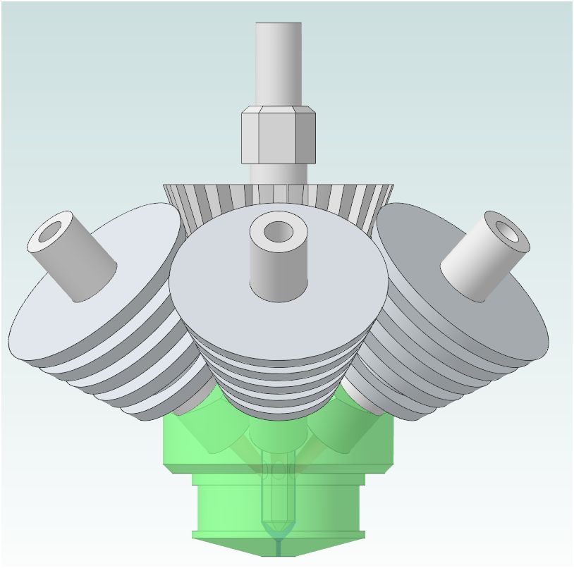
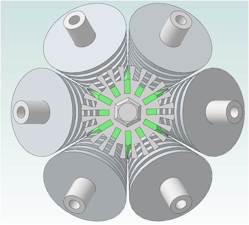
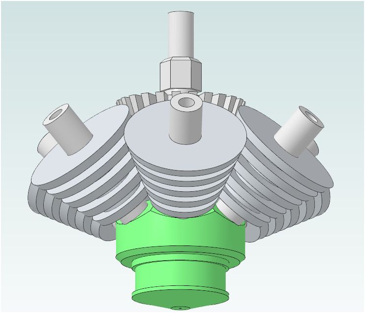
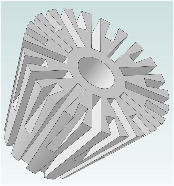
I've revised the 6 color - color mixing hot end to be smaller, lighter, and somewhat easier to build:
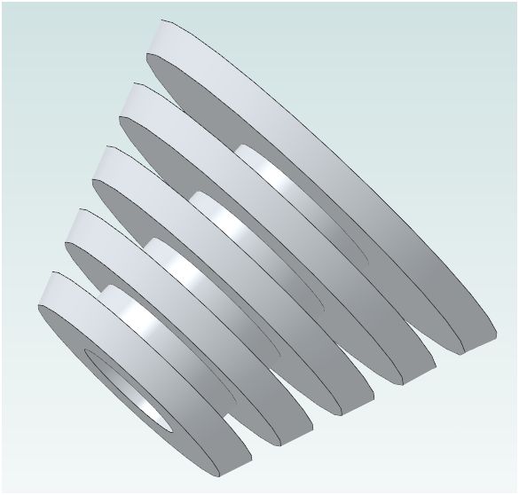
- It now uses heat sinks that can be made from 1" aluminum round stock instead of a water block. These can be made on a late or even a drill press.
- I shortened the Filament tubes and mixer tubes, and mixer shaft.
- A mounting plate can be screwed directly to the center heat sink, for mounting to the machine, and for mounting the mixer motor (DC or stepper). A baffle would need to be mounted between the heat sinks and the hotend body to keep air from blowing directly on it.
I have attached 6 views. The more images here.
One reason I'm posting this here and now (in addition to helping - I hope) is to make sure that these innovations remain free and open source. Death to patent trolls. I won't be building one for a while yet tho.
Here are some sources:
For HotEnd Body and Heat Sinks:
Copper Round-110 (cheapest copper)
Oxygen Free Copper Round 101 H04, highest thermal conductivity 223, or
Tellurium Copper-145 (high machinability) thermal conductivity: 204, or
Now here's a find:
1" Aluminum round 6063-T52, "fair" macinability, Thermal conductivity 209, and inexpensive!
304 Stainless tube for Filament Tubes, thermal conductivity <= 16
Stainless rod for Mixer Shaft
Edited 1 time(s). Last edit at 05/23/2013 09:35PM by Paul Wanamaker.
I've revised the 6 color - color mixing hot end to be smaller, lighter, and somewhat easier to build:
- It now uses heat sinks that can be made from 1" aluminum round stock instead of a water block. These can be made on a late or even a drill press.
- I shortened the Filament tubes and mixer tubes, and mixer shaft.
- A mounting plate can be screwed directly to the center heat sink, for mounting to the machine, and for mounting the mixer motor (DC or stepper). A baffle would need to be mounted between the heat sinks and the hotend body to keep air from blowing directly on it.
I have attached 6 views. The more images here.
One reason I'm posting this here and now (in addition to helping - I hope) is to make sure that these innovations remain free and open source. Death to patent trolls. I won't be building one for a while yet tho.
Here are some sources:
For HotEnd Body and Heat Sinks:
Copper Round-110 (cheapest copper)
Oxygen Free Copper Round 101 H04, highest thermal conductivity 223, or
Tellurium Copper-145 (high machinability) thermal conductivity: 204, or
Now here's a find:
1" Aluminum round 6063-T52, "fair" macinability, Thermal conductivity 209, and inexpensive!
304 Stainless tube for Filament Tubes, thermal conductivity <= 16
Stainless rod for Mixer Shaft
Edited 1 time(s). Last edit at 05/23/2013 09:35PM by Paul Wanamaker.
|
Re: Full Color 3d Printer Project May 24, 2013 08:11AM |
Registered: 11 years ago Posts: 369 |
i have been reading autodesk's partnering with makerbot with interest, they are going to mess up open source really well ...
______________________________________
__my mixed bag blog || aka --> [http] || ___ so 3D printing is everywhere ... dont worry, hospitals can now 3Dprint body parts, they will charge you $1million excluding surgical fees ... you will die paying your debts. thats their aim ___ if every patent expires tomorrow, everybody will surely get a 3dprinter and make EVERYTHING ! ____ there is a "DIY-DTG" t shirt printing forum, you can mod an EPSON printer to PRINT like a pro. ___ CNCzone? overly commercialized it seems ___ my country? they will be taxing you for every cm of road you use and track you to your grave using GPS and its government authorized, now they will fire all the traffic wardens instead.___ EEVBLOG? there is only 1 way to do things --> take it apart like a pro
|
Re: Full Color 3d Printer Project August 30, 2013 01:00AM |
I have been thinking a drawing along the same lines. I have surmised the need for only 5 nozzles though:
1. Red.
2. Yellow.
3. Blue.
4. White.
5. Support Material.
This is a historical set of subtractive primary colors. There is also the:
1. Red.
2. Green.
3. Blue.
4. White/Black.
5. Support Material.
Or the More modern printer Colors:
1. Cyan
2. Magenta
3. Yellow
4. Key or Black.
5. Support Material.
Note that no matter what your Tool Is programed to Mix You end up with 4 Colors and one support material. I copied your pics as I like your Design beater then mine. Also bummer about the Autodesk's partnering with makerbot, but good side is right now the "123D Design" by Autodesk's is currently free. It is not a Traditional Drafting Software package. But effective
Hop this adds to the discussion: Good work
1. Red.
2. Yellow.
3. Blue.
4. White.
5. Support Material.
This is a historical set of subtractive primary colors. There is also the:
1. Red.
2. Green.
3. Blue.
4. White/Black.
5. Support Material.
Or the More modern printer Colors:
1. Cyan
2. Magenta
3. Yellow
4. Key or Black.
5. Support Material.
Note that no matter what your Tool Is programed to Mix You end up with 4 Colors and one support material. I copied your pics as I like your Design beater then mine. Also bummer about the Autodesk's partnering with makerbot, but good side is right now the "123D Design" by Autodesk's is currently free. It is not a Traditional Drafting Software package. But effective
Hop this adds to the discussion: Good work
|
Re: Full Color 3d Printer Project August 30, 2013 01:19AM |
Registered: 11 years ago Posts: 44 |
The big reason for using both black and white is that it is going to be darn near realistically impossible to get black from 3 primary colors. it is part of the reason you have a black ink cartridge in your printer instead of of just cymk (besides the fact that black ink is cheaper). It would also make the color-mixing software more complicated if you wanted to print in grey or even darker colors for that matter.
Your 3rd set of 5 colors wont work for 3d printing (even a regular printer has 6+ colors, because you have to include the color of the paper, try printing white on colored or black paper.)
Your 3rd set of 5 colors wont work for 3d printing (even a regular printer has 6+ colors, because you have to include the color of the paper, try printing white on colored or black paper.)
|
Re: Full Color 3d Printer Project August 30, 2013 02:10AM |
We've been experimenting with a setup that looks very promising once we overcome a few technical hurdles. Using a Rostock-style delta machine, we deliver six colors to the print head via the six delta arms. Each arm is fabricated from pultruded carbon fiber tubing with a thin lining of aluminum tubing, inserted and bonded with epoxy. A PTFE-coated nichrome wire runs down the center of each tube, suspended at each end by friction grooves milled into specially modified ball joint rod ends. The nichrome wire passes current from the driven end of the tube, and is grounded back through the aluminum lining. Small diameter (yet still too heavy) heated hoses supply colored, pre-melted ABS to each of the driven ends of the heated delta arms, where it is delivered to the hot-end via channels bored through the delta platform, which is heated as well. The molten plastic is pumped through the hoses and arms at around 1200 psi by modified air-powered Nordsen pumps normally used in hot-glue box sealing machines. The pumps can deliver up to 3500 psi, but at around 800 psi, the ball joints start becoming stiff, causing resolution problems.
The hot-end is where the real magic happens, and we will be real proud of it when we get it working right. The hot-end design does not mix the colors internally at all, but rather externally via two coordinated mechanisms. We use the six delta arms to deliver colored material in order to mix colors using, roughly, a CYMK color space, with the addition of two white channels (one of which could be substituted by transparent material, if desired). Since the molten plastic is delivered under hydraulic pressure, and since the delivery tubes have very little residual pressure storage, flow is exceptionally manageable, and can be precisely controlled, however viscosity remains an issue. The hotend receives the material into six independent teardrop-shaped chambers surrounding a motor shaft passing through the center. These chambers form the upper valve body of the hot-end, which is clamped to the lower valve body where the rotating nozzle is mounted. Each chamber is separated from its corresponding nozzle port in the lower valve body by a tiny proportional spool valve. The outlet ports pass material into the rotating nozzle via six concentric channels that allow the plastic to exit the nozzle through six ports, each .03 in diameter, arranged in a closely packed hexagon. Since the spool valves can be proportionally driven, or switched off entirely, flow control at the nozzle is instantaneous. Color mixing, therefore, only requires position tracking, and translation of RGB color space to CYMK (and white). Actual mixing occurs after the plastic exits the nozzle, where it is stretched and twisted into a finely blended filament. Since the total volume of plastic exiting the nozxle is proportionately balanced by software, the fast acting valves can perform instant, full-bleed color changes, as well as pixel-perfect graphics features as fast as the printer can run!
The hot-end is where the real magic happens, and we will be real proud of it when we get it working right. The hot-end design does not mix the colors internally at all, but rather externally via two coordinated mechanisms. We use the six delta arms to deliver colored material in order to mix colors using, roughly, a CYMK color space, with the addition of two white channels (one of which could be substituted by transparent material, if desired). Since the molten plastic is delivered under hydraulic pressure, and since the delivery tubes have very little residual pressure storage, flow is exceptionally manageable, and can be precisely controlled, however viscosity remains an issue. The hotend receives the material into six independent teardrop-shaped chambers surrounding a motor shaft passing through the center. These chambers form the upper valve body of the hot-end, which is clamped to the lower valve body where the rotating nozzle is mounted. Each chamber is separated from its corresponding nozzle port in the lower valve body by a tiny proportional spool valve. The outlet ports pass material into the rotating nozzle via six concentric channels that allow the plastic to exit the nozzle through six ports, each .03 in diameter, arranged in a closely packed hexagon. Since the spool valves can be proportionally driven, or switched off entirely, flow control at the nozzle is instantaneous. Color mixing, therefore, only requires position tracking, and translation of RGB color space to CYMK (and white). Actual mixing occurs after the plastic exits the nozzle, where it is stretched and twisted into a finely blended filament. Since the total volume of plastic exiting the nozxle is proportionately balanced by software, the fast acting valves can perform instant, full-bleed color changes, as well as pixel-perfect graphics features as fast as the printer can run!
|
Re: Full Color 3d Printer Project August 30, 2013 03:07AM |
Registered: 12 years ago Posts: 80 |
Mark Bunds:
Your project sounds pretty awesome.
If you get it right you will have surmounted many tricky engineering hurdles. I could believe that while pre coloured filament may be the most repeatable way to get the CMYK colours it has a lot of 'heavy' mechanical overhead.
My first attempts would be to see if a non-solid master-batch pigment stream could be blended inside the nozzle. Having just one jumbo extruder might be easier than many small ones but I do not speak from experience here, just gut feel.
The proportional valves have always been my dream to add to a airbrush system where you can move your finger on a touch tablet with a colour map on it to select the CMYK mix of ink going to the venturi. The problem is that the venturi on the airbrush like the filament feed on the printer are not constant flow and will be hard to control in a proportional manner.
I thought if you could control the valves to allow mixing of the pigments in the selected ratios and then feed into the melt zone of the nozzle to extrude with the plastic like stripy toothpaste or flux cored solder. Obviously there needs to be enough blending to prevent unmixed pigment getting out, perhaps use a catalysed monomer carrier and have it polymerise with the heat. Colour changes will also be delayed a bit unlike the individual nozzle solution you are developing.
Good luck with your project, I hope it works out.
Kalle
--
Lahti, Finland
The only stable form of government is Open Source Government. - Kalle Pihlajasaari 2013
|
Re: Full Color 3d Printer Project August 30, 2013 05:52AM |
Registered: 15 years ago Posts: 242 |
CPS Wrote:
-------------------------------------------------------
> Ideas much appreciated (Very very rough write-up)
>
> Phase 1: Design of hardware+software
>
Additional: Look ahead code to forcast (and switch colours early) colour changes before they occur at the nozzle end such that each colour is primed and extrudes with no lag when needed at the print face. Currently, SW such as slic3r already has the option to upsuck and re-prime filament for cleaner transitions between non joining print faces.
>
> Phase 2: Analysis of color mixing proportions
> (calibrate model colors to %'s of each color As shown in richraps video, colour blending without deliberate mixing results in toothpaste like extrusion with colours stuck together but not intermingled. This complicates colour matching as the viewed colour varies depending on model orientation relative to ambient lighting and the viewer..
> required)
> Phase 3: Improvements and updates
>
> Info needed:
>
My CNC/extruder creation: [grael-minifactory.blogspot.com]
-------------------------------------------------------
> Ideas much appreciated (Very very rough write-up)
>
> Phase 1: Design of hardware+software
>
- >
- Extruder-Hot End Stick with one heater, one thermister, one nozzle diameter, it works.
> - Extruder-Cold End Bowden tubes aligned for converging entry into low volume hot end.
> - Modifications to Extruder Carriage Very machine dependent. Not such an issue with bowden cables.
> - Motor Selection Leave the extrude gcodes as is but introduce mixing command gcodes used to initialise and at any new setting.
> - Cable Management (electronics and filament) Just more.
> - Software Given specified extrude rate/lengths, apportion individual spool extrude rates based on current blend proportions.
>
Additional: Look ahead code to forcast (and switch colours early) colour changes before they occur at the nozzle end such that each colour is primed and extrudes with no lag when needed at the print face. Currently, SW such as slic3r already has the option to upsuck and re-prime filament for cleaner transitions between non joining print faces.
>
> Phase 2: Analysis of color mixing proportions
> (calibrate model colors to %'s of each color As shown in richraps video, colour blending without deliberate mixing results in toothpaste like extrusion with colours stuck together but not intermingled. This complicates colour matching as the viewed colour varies depending on model orientation relative to ambient lighting and the viewer..
> required)
> Phase 3: Improvements and updates
>
> Info needed:
>
- >
- PCB to support 10-11+ stepper(maybe servo)
> drivers (X, Y, Z, Red,Yellow, Blue, Black, White,
> "transparent"[if effective], and support
> filaments) (mixer may or may not be able to just
> "run" at same speed, simple DC motor maybe)
> (support possibly on separate extruder)
Thats a LOT of steppers. I've got 4 steppers full control (PWM sine wave), 5 servo, 5 PWM and a lot of other stuff on the board I designed but 10+ steppers would need a bigger than 100 pin Arm chip to drive unless I switched to smart stepper mosfet drivers like the Alegro ones many are using. Delta calculations require significantly more processor cycles than the traditional XYZ configurations. Ideally, the driver chips would have a chip select pin so that a common bus could be used for control, but the individual driver chip would have to be selected before sending the direction and step signals. SPI or I2C ought to be another fast enough alternative. 4 drivers prefitted and daisy chainable extension to any additional steppers.
Potentially, a powered stirrer could be used poking into the hot end cavity to disrupt the toothpaste effect if required.
> - Software to use G-code values for different As above. Note that trace colours may be significantly more difficult to accurately prime, especially with retraction complexities. Should still be able to be solved though, it's just a matter of perfecting a basic bicolour prodedure that works, then expanding parametrically for as many spools and extrude feeders are available Different materials may require individual processing settings to compensate for variation in physical handling properties and different compression amounts in a bowden tube..
> values of amount of each filament to use
> - Servo motors vs Stepper motors (for X/Y/Z vs
> filament feeder vs extruder) I think servo motors for filament extrude control would be a step backwards.
> - Mixing efficiency strategies
> - Most efficient XYZ movement method (most
> common, potter's wheel, or some other complicated
> setup)
>
My CNC/extruder creation: [grael-minifactory.blogspot.com]
|
Re: Full Color 3d Printer Project August 30, 2013 11:33AM |
We've been experimenting with a setup that looks very promising once we overcome a few technical hurdles. Using a Rostock-style delta machine, we deliver six colors to the print head via the six delta arms. Each arm is fabricated from pultruded carbon fiber tubing with a thin lining of aluminum tubing, inserted and bonded with epoxy. A PTFE-coated nichrome wire runs down the center of each tube, suspended at each end by friction grooves milled into specially modified ball joint rod ends. The nichrome wire passes current from the driven end of the tube, and is grounded back through the aluminum lining. Small diameter (yet still too heavy) heated hoses supply colored, pre-melted ABS to each of the driven ends of the heated delta arms, where it is delivered to the hot-end via channels bored through the delta platform, which is heated as well. The molten plastic is pumped through the hoses and arms at around 1200 psi by modified air-powered Nordsen pumps normally used in hot-glue box sealing machines. The pumps can deliver up to 3500 psi, but at around 800 psi, the ball joints start becoming stiff, causing resolution problems.
The hot-end is where the real magic happens, and we will be real proud of it when we get it working right. The hot-end design does not mix the colors internally at all, but rather externally via two coordinated mechanisms. We use the six delta arms to deliver colored material in order to mix colors using, roughly, a CYMK color space, with the addition of two white channels (one of which could be substituted by transparent material, if desired). Since the molten plastic is delivered under hydraulic pressure, and since the delivery tubes have very little residual pressure storage, flow is exceptionally manageable, and can be precisely controlled, however viscosity remains an issue. The hotend receives the material into six independent teardrop-shaped chambers surrounding a motor shaft passing through the center. These chambers form the upper valve body of the hot-end, which is clamped to the lower valve body where the rotating nozzle is mounted. Each chamber is separated from its corresponding nozzle port in the lower valve body by a tiny proportional spool valve. The outlet ports pass material into the rotating nozzle via six concentric channels that allow the plastic to exit the nozzle through six ports, each .03 in diameter, arranged in a closely packed hexagon. Since the spool valves can be proportionally driven, or switched off entirely, flow control at the nozzle is instantaneous. Color mixing, therefore, only requires position tracking, and translation of RGB color space to CYMK (and white). Actual mixing occurs after the plastic exits the nozzle, where it is stretched and twisted into a finely blended filament. Since the total volume of plastic exiting the nozxle is proportionately balanced by software, the fast acting valves can perform instant, full-bleed color changes, as well as pixel-perfect graphics features as fast as the printer can run!
The hot-end is where the real magic happens, and we will be real proud of it when we get it working right. The hot-end design does not mix the colors internally at all, but rather externally via two coordinated mechanisms. We use the six delta arms to deliver colored material in order to mix colors using, roughly, a CYMK color space, with the addition of two white channels (one of which could be substituted by transparent material, if desired). Since the molten plastic is delivered under hydraulic pressure, and since the delivery tubes have very little residual pressure storage, flow is exceptionally manageable, and can be precisely controlled, however viscosity remains an issue. The hotend receives the material into six independent teardrop-shaped chambers surrounding a motor shaft passing through the center. These chambers form the upper valve body of the hot-end, which is clamped to the lower valve body where the rotating nozzle is mounted. Each chamber is separated from its corresponding nozzle port in the lower valve body by a tiny proportional spool valve. The outlet ports pass material into the rotating nozzle via six concentric channels that allow the plastic to exit the nozzle through six ports, each .03 in diameter, arranged in a closely packed hexagon. Since the spool valves can be proportionally driven, or switched off entirely, flow control at the nozzle is instantaneous. Color mixing, therefore, only requires position tracking, and translation of RGB color space to CYMK (and white). Actual mixing occurs after the plastic exits the nozzle, where it is stretched and twisted into a finely blended filament. Since the total volume of plastic exiting the nozxle is proportionately balanced by software, the fast acting valves can perform instant, full-bleed color changes, as well as pixel-perfect graphics features as fast as the printer can run!
|
Re: Full Color 3d Printer Project September 01, 2013 03:21AM |
Registered: 10 years ago Posts: 580 |
That's really interesting Mark, I'd love to see pictures/video when you're ready! Great work everyone.
For filament colors: I think it may be necessary to use both grey and black to get the full range, as according to Myles Corbett's research - black has very strong pigment, so it may be a bit touchy to use.
I've been designing a Rostock that will have a 14 x 26 inch build area, and magnetic ball joints. I inserted the model of my 6-color hot-end and found that it is a bit too large - since the bowden tubes flare out and would hit the arm rods when printing near the outer edges. I will re-design that after the Rostock is finished.
I just have to say I really love Alibre Design (Personal Edition). The model components can easily be aligned and attached so they move realistically. I can drag the effector around and the rods and bearing assemblies all move appropriately. This is allowing me to fully test each component for interference, etc. For instance a full sized Dremel will fit nicely (so I can drill PCB's). BTW, I believe I have greatly simplified the design and construction of magnetic ball joints, and will write about that in another thread after I have tested it.
|
Re: Full Color 3d Printer Project September 30, 2013 07:37PM |
Registered: 10 years ago Posts: 4 |
CPS Wrote:
-------------------------------------------------------
> @dronus, The purpose of this project is to do
> multi-color 3d printer, mixing several materials
> will be challenging yes, but not useless
>
> @Simba, how do you control the flow of powder to
> the hot end? Also, according to Jacqyard Products:
> "Works great on paper, clay, metal, wood or
> plastic and cleans up easily with water." Wouldn't
> it just get washed out if the plastic part gets
> wet?
>
> The idea is to used the color mix'ed plastic on
> the outside of the part and the "partially mixed"
> to be used the infill and in certain situations,
> put it in a throw away pile of plastic of some
> sort.
>
> I'll post a 1st draft cad file as soon as i get
> decent internet connection (to download AutoCad,
> had to clean out computer awhile ago), probably
> later this week
>
> Really important info I need help finding... Board
> to be able to use so many motors, software to
> accommodate using more than 1 color at a time and
> transfering to G code, possibly usb/SD
> connectivity
>
> Will probably need to test filaments individually
> for color calibration
>
> err why can I not edit my first post, it is kind
> of important to be able to update it...
what about using hot air? Mix the cmyk colored particles before its blown into a ABS chamber?
Mixing of color is done from 4 containers,supported by air pressure. Each container contains c m y k colored particles and their output is small enough to blow 256 diffrent amount of particles into, Howto clean chamber before extruding new pellet, I have no idea
or feeding the cyan, magenta, yellow and black ABS into a fast rotating "knife"/laser? which cuts of proper length of each according to a 256 color spectre. (Donno yet if such a "knife" exists). Then the cutted parts are mixed into a chamber.The chamber opens for flow according to g-commands. Again howto rinse btwn extruder output? or be able to totally empty chamber in extruder before next point of print?
A rotating extruder whith holes should clean up rests of abs and force the non printed abs into a trashcan?
regards
Edited 2 time(s). Last edit at 09/30/2013 07:59PM by knut.
|
Re: Full Color 3d Printer Project October 07, 2013 08:51PM |
Registered: 10 years ago Posts: 34 |
I was asking on the google+ site a little bit today about this (I don't know how to provide a URL from g+, sorry!) , but what about using an inkjet printer heat to do all the colorizing for you? You could print a layer, and then have the printer head color the parameter with the ink.
A few issues:
1) You'd need a dye that would soak into the material. A solvent based ink could probably soak into ABS but you'd have to make sure there isn't pitting.
2) You'd need to make sure that the temperature of that layer didn't drop too much. It was noted that ABS won't still to something if it is cool. Using a water based dye where it doesn't immediately evaporate could be trouble.
3) The Inkshield may be a good way to deposit it but there hasn't been a large amount of development since it came out. It can only do one color at the moment, for example although it is stackable.
If you could get this to work it could potentially be a much better way than mixing filaments. This is in fact how professional powder printers work and they can get several hundred thousand colors this way.
What do you guys think? Has anyone been working on this?
Edited 1 time(s). Last edit at 10/07/2013 08:51PM by Coherent.
|
Re: Full Color 3d Printer Project October 26, 2013 06:27PM |
Registered: 10 years ago Posts: 115 |
I like the idea of using an inkjet printhead after each layer. With the evaporation issue you could use the heat from the hotend to rapidly evaporate the water before continuing with the next layer. Another idea that popped into my head is to vary the intensity of the colour by adjusting the distance from the perimeter you eject the ink. That would allow you to simplify the ink deposition since you only have to worry about constant flow or no flow.
EDIT: It may be possible to deposit ink using a needle and a piezo transducer. A pulse on the piezo would send a drop flying out of the needle. If you change the frequency of the drops as the printhead is moving then you can vary the intensity of the colour. I require injections regularly for medical reasons, so I may repurpose one into an ink nozzle. I'll have to take precautions with the sharp point before starting however.
EDIT2: Did a crude test with water. but no success. A better solution needs to use the entire surface area of the piezo to create enough pressure. Seems to have been some success already: [reprap.org]
Edited 3 time(s). Last edit at 10/26/2013 08:00PM by samp20.
|
Re: Full Color 3d Printer Project October 27, 2013 05:05PM |
Registered: 10 years ago Posts: 115 |
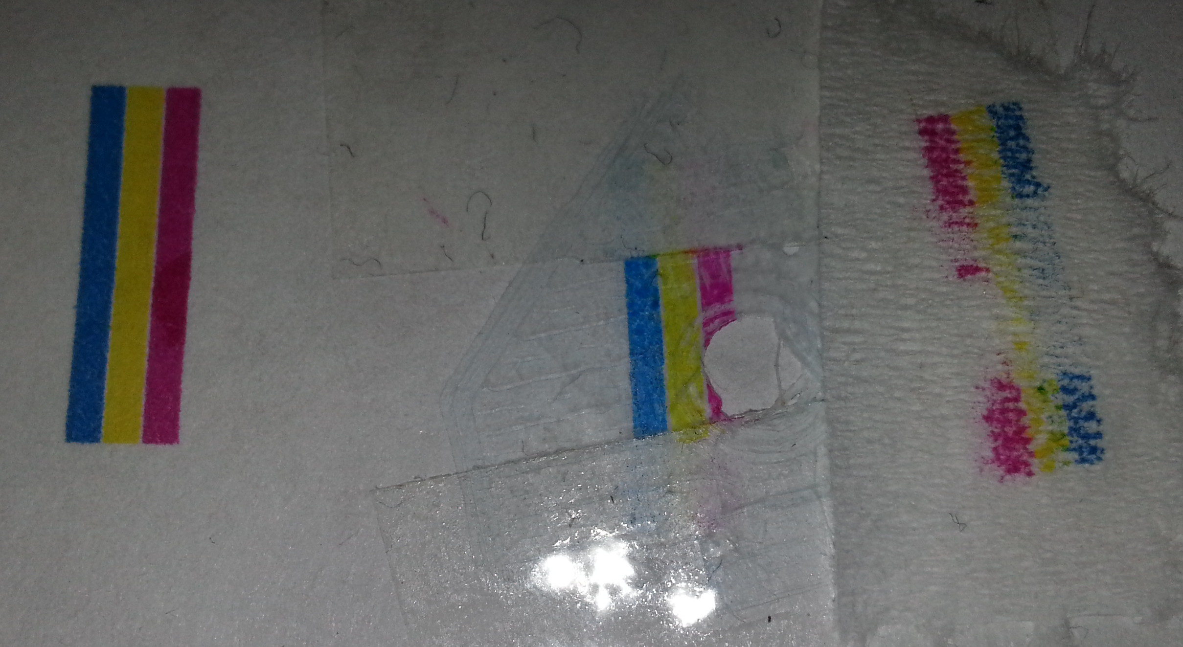
I decided to do another experiment to see how well printer ink adheres to the plastics we use. From a failed print I managed to acquire a thin film of PLA. I then taped that to a piece of paper and fed it through my canon printer which contains a CL511 FINE cartridge. The attached image shows the results. The left ink is on paper, the middle on the PLA, and the right is what was absorbed in a piece of tissue. The PLA absorbed most of the ink, and the colour is clearly visible. A little did lift off onto the tissue however. Once the ink has dried it will rub off eventually with your finger, so the print would need to be painted with varnish or something similar to protect it.
|
Re: Full Color 3d Printer Project November 05, 2013 01:46AM |
Registered: 10 years ago Posts: 34 |
|
Re: Full Color 3d Printer Project November 24, 2013 11:52AM |
Registered: 12 years ago Posts: 325 |
Is there any open source software out there for working with files with color info, like AMF or OBJ? Anything that could be used for painting objects via the gcode, with an appropriate extruder? What software is used with experimental color extruders? I believe all commercial color printer use proprietary software for painting the objects… Has anyone experimented along these lines?
These are great experiments, and oculd help FDM stay competitive...
These are great experiments, and oculd help FDM stay competitive...
|
Re: Full Color 3d Printer Project November 28, 2013 12:46AM |
Registered: 11 years ago Posts: 791 |
Quote
paucus
Someone did some experiments with coloring the white filament with whiteboard markers, and it seemed promising. Mark the filament before you heat it, but the software needs to estimate accurately how much filament it is using, so it can color it ahead of the time it will need it... what do you think?
Or what about injecting dye? of course you have to heat it so it won't steam and make bubbles...
I did some experiments with using sublimation ink. I just wiped a bit of ink onto some white filament to see what would happen.
The sublimation ink turns into a gas that is absorbed inside the plastic, it becomes permanent and solid colour.
If there where some means of applying the ink at the right time and the correct colour of course, the printed part would be in full colour.
[regpye.com.au]
"Experience is the mother of all knowledge." --Leonardo da Vinci
|
Re: Full Color 3d Printer Project November 28, 2013 07:29AM |
Registered: 12 years ago Posts: 325 |
If you could inject the ink at the transition zone, that would be ideal, as long as it did not boil and cause the plastic to be extruded violently. You'd have to inject it in very small controlled doses to get any kind of precision. I'm not sure you really need the plastic itself to be colored, you could color the object directly after extrusion. We tested applying magic markers to the object, right after building the layer. The result is promising. Maybe you could apply it around the nozzle as it's being printed, if you can resolve that it needs to be applied in 360º...
The other area that needs to be worked on is how to specify colors for an object and how to use that info in the slicer and the gcode (driver). I have not found any open source software for doing this, nor much info. It's all proprietary...
Regards,
Paucus
The other area that needs to be worked on is how to specify colors for an object and how to use that info in the slicer and the gcode (driver). I have not found any open source software for doing this, nor much info. It's all proprietary...
Regards,
Paucus
|
Re: Full Color 3d Printer Project December 02, 2013 05:50PM |
Registered: 12 years ago Posts: 325 |
inkjet, markers, dyes and powders, but all applied after putting a layer of white plastic... to me that seems like the way that will give the most flexible results. It does depend on plastic adhering between layers, but it should not be a big problem.
How do you put the color info in the STL and in the gcode, though? better sw is needed.
Paucus
How do you put the color info in the STL and in the gcode, though? better sw is needed.
Paucus
|
Re: Full Color 3d Printer Project December 28, 2013 11:26AM |
Registered: 11 years ago Posts: 374 |
Anyone up for filing disputes on this patent application, since we discussed this method extensively in this forum?
[www.3ders.org]
[www.3ders.org]
|
Re: Full Color 3d Printer Project December 28, 2013 04:57PM |
Registered: 10 years ago Posts: 1,381 |

It's been done before with a filament:
6-axis 3D Printer
[www.youtube.com]
Edited 1 time(s). Last edit at 12/28/2013 04:58PM by A2.
|
Re: Full Color 3d Printer Project - hot end design December 28, 2013 05:07PM |
Admin Registered: 13 years ago Posts: 730 |
Quote
crispy1
Anyone up for filing disputes on this patent application, since we discussed this method extensively in this forum?
By "in this forum" do you mean in this particular thread? The patent application was filed in July 2012, months before this thread existed. Here's more info on the application:
INKJET PRINTER FOR PRINTING ON A THREE-DIMENSIONAL OBJECT AND RELATED APPARATUS AND METHOD
United States Patent Application 20130342592
Filed July 3, 2012
link
The claims are listed below (sorry for wall of text). Where exactly in the forum discussion were these claims anticipated? I am not sure what the rules are (like I've said before - it's complicated and it depends on the country) but I think that in order to challenge a patent application, the challenger would need to have reduced the invention to practice prior (and perhaps as much as one year prior) to the filing date of the application. I don't think kicking around ideas in a forum thread counts as reduction to practice... but I could be wrong.
It would be great to get an IP lawyer to explain this stuff to us sometime.
I don't think the RepRap community has any credible case challenging this particular patent appliction. Even if they did, who would pay for it? Who would champion it?
Quote
20130342592
What is claimed is:
1. An assembly configured for adjusting a position of a three-dimensional object in an inkjet printer, the assembly comprising: a fixture configured to hold a circuit board such that first and second nonparallel surfaces of the circuit board are exposed; a tilt adjustment mechanism coupled to the fixture and configured to adjust a tilt angle of the circuit board; and a rotational adjustment mechanism coupled to the fixture and configured to adjust an angular position of the circuit board, wherein the tilt adjustment mechanism and the rotational adjustment mechanism are configured to upwardly orient the first and second nonparallel surfaces of the circuit board.
2. The assembly of claim 1, further comprising a vertical adjustment mechanism coupled to the fixture and configured to adjust a vertical position of the circuit board.
3. The assembly of claim 1, wherein the tilt adjustment mechanism is configured to tilt the first and second nonparallel surfaces of the circuit board to the tilt angle at least about 45 degrees from vertical.
4. The assembly of claim 1, wherein the rotational adjustment mechanism comprises a rotatable shaft.
5. The assembly of claim 4, wherein the tilt adjustment mechanism comprises a hinge coupled to the rotatable shaft.
6. An inkjet printer configured for printing on a three-dimensional object, comprising: a print head configured to eject an ink; and an assembly configured for adjusting a position of a circuit board relative to the print head, the assembly comprising: a fixture configured to hold the circuit board such that first and second nonparallel surfaces of the circuit board are exposed; a tilt adjustment mechanism coupled to the fixture and configured to adjust a tilt angle of the circuit board; and a rotational adjustment mechanism coupled to the fixture and configured to adjust an angular position of the circuit board, wherein the tilt adjustment mechanism and the rotational adjustment mechanism are configured to upwardly orient the first and second nonparallel surfaces of the circuit board.
7. The inkjet printer of claim 6, further comprising a vertical adjustment mechanism configured to adjust a separation distance between the print head and the circuit board.
8. The inkjet printer of claim 7, wherein the vertical adjustment mechanism is configured to adjust a vertical position of the circuit board.
9. The inkjet printer of claim 7, wherein the vertical adjustment mechanism is configured to adjust a vertical position of the print head.
10. The inkjet printer of claim 6, further comprising a horizontal adjustment mechanism configured to adjust a horizontal position of the print head.
11. The inkjet printer of claim 10, wherein the horizontal adjustment mechanism is configured to adjust the horizontal position of the print head along first and second axes.
12. The inkjet printer of claim 6, wherein the tilt adjustment mechanism is configured to tilt the first and second nonparallel surfaces of the circuit board to the tilt angle of at least about 45 degrees from vertical.
13. The inkjet printer of claim 6, further comprising a pretreatment apparatus configured to direct a pretreatment onto the circuit board.
14. The inkjet printer of claim 13, wherein the pretreatment apparatus is coupled to the print head.
15. The inkjet printer of claim 6, further comprising a curing apparatus configured to cure the ink.
16. The inkjet printer of claim 15, wherein the curing apparatus is coupled to the print head.
17. The inkjet printer of claim 6, further comprising an insulation remover.
18. A method for inkjet printing on a three-dimensional object, comprising: positioning a circuit board proximate a print head such that a first surface and a second surface that are nonparallel are exposed and the first surface is upwardly oriented; ejecting a conductive ink onto the first surface of the circuit board; adjusting a position of the circuit board such that the second surface is upwardly oriented; and ejecting the conductive ink onto the second surface of the circuit board.
19. The method of claim 18, wherein adjusting the position of the circuit board comprises adjusting a tilt angle of the circuit board.
20. The method of claim 18, wherein adjusting the position of the circuit board comprises adjusting an angular position of the circuit board.
21. The method of claim 18, further comprising directing a pretreatment onto the first surface prior to ejecting the conductive ink onto the first surface; and directing the pretreatment onto the second surface prior to ejecting the conductive ink onto the second surface.
22. The method of claim 18, further comprising curing the conductive ink.
|
Re: Full Color 3d Printer Project December 28, 2013 05:27PM |
Admin Registered: 13 years ago Posts: 730 |
While we're on the subject... People might like this resource from the Public Patent Foundation:
"This is PUBPAT's free instructional program that details how to find prior art for issued patents. The hour long audio recording with supporting written materials uses a model patent as the basis for examples during the session."
Link here
"This is PUBPAT's free instructional program that details how to find prior art for issued patents. The hour long audio recording with supporting written materials uses a model patent as the basis for examples during the session."
Link here
|
Re: Full Color 3d Printer Project - hot end design December 28, 2013 05:46PM |
Registered: 12 years ago Posts: 325 |
I think a number of reprap hobbyists have probably come up with this idea on their own, but the trick is getting it done, not imagining it. Is apple patenting the idea or a specific mechanism? because putting an inkjet to paint objets, and tilting a head so it gets better reach, are not very novel ideas. There are several 3D printing technologies that already use inkjet heads but on powder, to color the object. This seems to be using an inkjet to color an FDM type printer, but it's a small extension. I hope they don't get a patent for the idea of combining inkjets and FDM per-se, as anyone in this field could have suggested it (of course, actual implementation is another, more costly, affair).
Paucus
Edited 1 time(s). Last edit at 12/28/2013 05:47PM by paucus.
Paucus
Edited 1 time(s). Last edit at 12/28/2013 05:47PM by paucus.
|
Re: Full Color 3d Printer Project December 28, 2013 06:47PM |
Admin Registered: 13 years ago Posts: 730 |
Quote
paucus
This seems to be using an inkjet to color an FDM type printer
No. It doesn't have anything to do with FDM.
Edit: Apologies, paucus. I realized your comment could be read two different ways. I thought you were saying that the patent application is about FDM. The topic of thread, of course, is all about coloring a plastic part made by FFF.
Edited 1 time(s). Last edit at 12/28/2013 07:11PM by MattMoses.
|
Re: Full Color 3d Printer Project April 21, 2014 06:42PM |
Registered: 12 years ago Posts: 325 |
I just published our research on FDM color printing using magic markers, you may be interested (crossposting, sorry).
Now the real challenge is to do this with an inkjet... ?
Paucus
Kikai Labs
Edited 1 time(s). Last edit at 04/21/2014 06:47PM by paucus.

Now the real challenge is to do this with an inkjet... ?
Paucus
Kikai Labs
Edited 1 time(s). Last edit at 04/21/2014 06:47PM by paucus.
|
Re: Full Color 3d Printer Project May 20, 2014 08:54AM |
Registered: 9 years ago Posts: 3 |
Hi all,
I have just read this thread with great interest.
I may have a short term offering to one of the issues mentioned in the very first post :
I am interested less so in the full colour aspect but more in the adaptive material side, which is to be able to specify different flexibility ratios to different zones of the model. This will be achieved using the following workflow idea:
1. Split the stl model up into various parts, each reflecting a specific mix ratio of flexibility.
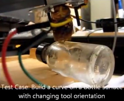
2. Run current slicing software for dual extrusion. I use Slic3r which outputs specific extruder change Gcodes "T1" "T2" etc for each area of the model (see video).
3. Run a post processor plugin that will search for the extruder change "T" codes. Once found, replace the respective "E" values with a recalculated "A" and "B" value based upon the mix percentages required.
4. Run Gcode through a modified firmware that can use A and B values (or similar Codes) to drive independent extruders. I believe Sailfish can use A and B values but I haven't found a flavour of Ramps firmware that can.
I have created a "Gcode Filament Mixer" script video that shows you the Gcode mixing process. I have also attached before (Input.gcode) and after (output.gcode) Gcode files for anyone who wishes to analyse them :
Gcode Filament Mixer - YouTube
It is easy for me to change the script to mix more than two extruders (for colour mixing) and output A,B,C,D,J and K etc (J.Corbett Page 29)
I have currently set 10 mix ratios, more can be added. Please remember this was to create different flexibilities where there are only two input filaments (flexible and non flexible)
Long term, I expect slicing software to be able to output multiple extruder Gcode values on the same line, and firmware / hardware capable of driving multiple extruder's simultaneously independent!!!
I am happy to work with anyone who wishes to take this further.
Many thanks,
Steve Wood - AKA Gyrobot.
Edited 4 time(s). Last edit at 05/20/2014 03:52PM by Gyrobot.
I have just read this thread with great interest.
I may have a short term offering to one of the issues mentioned in the very first post :
Quote
Software to use G-code values for different values of amount of each filament to use
I am interested less so in the full colour aspect but more in the adaptive material side, which is to be able to specify different flexibility ratios to different zones of the model. This will be achieved using the following workflow idea:
1. Split the stl model up into various parts, each reflecting a specific mix ratio of flexibility.
2. Run current slicing software for dual extrusion. I use Slic3r which outputs specific extruder change Gcodes "T1" "T2" etc for each area of the model (see video).
3. Run a post processor plugin that will search for the extruder change "T" codes. Once found, replace the respective "E" values with a recalculated "A" and "B" value based upon the mix percentages required.
4. Run Gcode through a modified firmware that can use A and B values (or similar Codes) to drive independent extruders. I believe Sailfish can use A and B values but I haven't found a flavour of Ramps firmware that can.
I have created a "Gcode Filament Mixer" script video that shows you the Gcode mixing process. I have also attached before (Input.gcode) and after (output.gcode) Gcode files for anyone who wishes to analyse them :
Gcode Filament Mixer - YouTube
It is easy for me to change the script to mix more than two extruders (for colour mixing) and output A,B,C,D,J and K etc (J.Corbett Page 29)
I have currently set 10 mix ratios, more can be added. Please remember this was to create different flexibilities where there are only two input filaments (flexible and non flexible)
Long term, I expect slicing software to be able to output multiple extruder Gcode values on the same line, and firmware / hardware capable of driving multiple extruder's simultaneously independent!!!
I am happy to work with anyone who wishes to take this further.
Many thanks,
Steve Wood - AKA Gyrobot.
Edited 4 time(s). Last edit at 05/20/2014 03:52PM by Gyrobot.
|
Re: Full Color 3d Printer Project May 21, 2014 11:34PM |
Registered: 11 years ago Posts: 364 |


Sorry, only registered users may post in this forum.