Introducing the ramps 10 - "Ramps10" an open source multi-configurable stepper controller shield based on the Ramps 1.4 design.
Posted by Simba
|
Re: Introducing the ramps 10 - "Ramps10" an open source multi-configurable stepper controller shield based on the Ramps 1.4 design. April 17, 2013 03:14PM |
Registered: 11 years ago Posts: 8 |
ThrustMe Wrote:
-------------------------------------------------------
> Simba Wrote:
> [about linking stepper motor drivers such as StepSticks for higher current output]
> > It is important that linking two chips works.
> I
> > can't see why it wouldn't - sharing the load,
>
> It won't work, and it is obvious why if you
> look at the data sheet for any of those chips. You
> will inevitably end up with one driver trying to
> pull an output high while the other driver is
> trying to pull the same output low, simply because
> the power switches aren't synchronised between the
> two drivers.
I forgot to add that if your 2-phase motor is a unipolar, 8-wire version, then it ought to be fine to have each separate pair of phase windings connected to one StepStick each.
|
Re: Introducing the ramps 10 - "Ramps10" an open source multi-configurable stepper controller shield based on the Ramps 1.4 design. May 05, 2013 01:34AM |
Registered: 11 years ago Posts: 482 |
At present, I'm not entirely confident about the G3D stepstick anymore. I burnt one that came from G3D, and one that we made from scratch so far, just by running the default settings with a 1.66 amp motor. If things persist like this, I would switch to using a more expensive driver... looking into a 3.5A one in fact. Then I would propose this time, claiming only 2.5A current driving (leaving a 1A safety factor) to achieve the original goals set out.
|
Re: Introducing the ramps 10 - "Ramps10" an open source multi-configurable stepper controller shield based on the Ramps 1.4 design. May 05, 2013 01:37AM |
Registered: 11 years ago Posts: 482 |
ThrustMe Wrote:
-------------------------------------------------------
> Simba Wrote:
>
> > It is important that linking two chips works.
> I
> > can't see why it wouldn't - sharing the load,
>
> It won't work, and it is obvious why if you
> look at the data sheet for any of those chips. You
> will inevitably end up with one driver trying to
> pull an output high while the other driver is
> trying to pull the same output low, simply because
> the power switches aren't synchronised between the
> two drivers.
>
> Additionally, most of these stepper motor
> driver chips use low side current sensing. If the
> current sensing resistors' ground ends are not
> insulated from one another, the current passing
> through each resistor will be a mixture of the
> current supplied by each chip. Load sharing won't
> work properly and/or reliably then, although with
> closely matched power switches, such as multiple
> outputs from the same chip, it would likely work
> well enough.
>
> > It certainly works in the opposite direction
> (one stepstick, two motors).
>
> One output connected to two inputs, which is
> completely different from two outputs connected to
> one input.
It's obvious, and we are going to do it and prove you right, and hopefully make some smoke, and learn something in the process. I have a theory it can work as it, i just wish the theory supported it. Perhaps there is enough lag between components + inductance that it would naturally distribute forces amongst the controllers. I'll start by trying to put 3A into a nema 23.
|
Re: Introducing the ramps 10 - "Ramps10" an open source multi-configurable stepper controller shield based on the Ramps 1.4 design. May 10, 2013 03:17AM |
Registered: 10 years ago Posts: 7 |
Simba Wrote:
-------------------------------------------------------
> At present, I'm not entirely confident about the
> G3D stepstick anymore. I burnt one that came from
> G3D, and one that we made from scratch so far,
> just by running the default settings with a 1.66
> amp motor. If things persist like this, I would
> switch to using a more expensive driver... looking
> into a 3.5A one in fact. Then I would propose
> this time, claiming only 2.5A current driving
> (leaving a 1A safety factor) to achieve the
> original goals set out.
You wrongly understand - maximum output of drivers and drivers IC with what actually is possible - you need very very big heatsink or very very strong air flow to let for any driver working at 2A (even if this driver can output 4A) - incrassing ampers output incrase heat produced and by incrasing voltage from 12V into 24V happen exactly same story - more watts = more heat.
About 1.7A limit somehow you are right, due of we used 0.1ohm 1/4W resistors this incrase maximal output vs StepStick and other variations with 0.2ohm 1/4W but 1/4 for resistor the trully is too less for give real 2A output it can but it is below the sense resistors limit.
But is hard for me to belive that your G3D driver burn - A4988 have overcurrent and overheat protection which mainly result that I never heared about burned G3D driver since we selling it, but shortcuts and inserting in wrong direction is harmfull and resulting in burn.
Using 3.5A drivers is more complicate story if you want to keep PCB as G3D or other reprap drivers shape - you have to use bigger sense resistor and forget about 1/4 or 1/2W sense resistor if you want to run this in 0.1ohm configuration then 1W resistor is must to be to work safe at 2.5A or very low value sense resistors plus tracks of width 1.5mm for coils output.
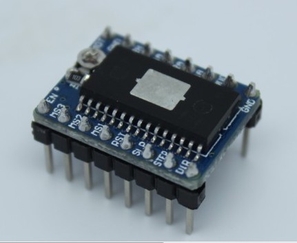
Just now we testing some new G3D driver PM me and I can shipping to you few pcs. of it - it is 2.2A driver with 1/128 step mode (picture attached to my message).
Best Regards
Martin
www.gadgets3d.com - parts for your 3D printer
Edited 2 time(s). Last edit at 05/10/2013 03:27AM by Martin_G3D.
-------------------------------------------------------
> At present, I'm not entirely confident about the
> G3D stepstick anymore. I burnt one that came from
> G3D, and one that we made from scratch so far,
> just by running the default settings with a 1.66
> amp motor. If things persist like this, I would
> switch to using a more expensive driver... looking
> into a 3.5A one in fact. Then I would propose
> this time, claiming only 2.5A current driving
> (leaving a 1A safety factor) to achieve the
> original goals set out.
You wrongly understand - maximum output of drivers and drivers IC with what actually is possible - you need very very big heatsink or very very strong air flow to let for any driver working at 2A (even if this driver can output 4A) - incrassing ampers output incrase heat produced and by incrasing voltage from 12V into 24V happen exactly same story - more watts = more heat.
About 1.7A limit somehow you are right, due of we used 0.1ohm 1/4W resistors this incrase maximal output vs StepStick and other variations with 0.2ohm 1/4W but 1/4 for resistor the trully is too less for give real 2A output it can but it is below the sense resistors limit.
But is hard for me to belive that your G3D driver burn - A4988 have overcurrent and overheat protection which mainly result that I never heared about burned G3D driver since we selling it, but shortcuts and inserting in wrong direction is harmfull and resulting in burn.
Using 3.5A drivers is more complicate story if you want to keep PCB as G3D or other reprap drivers shape - you have to use bigger sense resistor and forget about 1/4 or 1/2W sense resistor if you want to run this in 0.1ohm configuration then 1W resistor is must to be to work safe at 2.5A or very low value sense resistors plus tracks of width 1.5mm for coils output.
Just now we testing some new G3D driver PM me and I can shipping to you few pcs. of it - it is 2.2A driver with 1/128 step mode (picture attached to my message).
Best Regards
Martin
www.gadgets3d.com - parts for your 3D printer
Edited 2 time(s). Last edit at 05/10/2013 03:27AM by Martin_G3D.
|
Re: Introducing the ramps 10 - "Ramps10" an open source multi-configurable stepper controller shield based on the Ramps 1.4 design. May 14, 2013 07:04PM |
Registered: 10 years ago Posts: 38 |
Hi all,
I'm comparatively new to RepRap so I'm still in the 'hyper-inquisitve' phase. (I've barely just started my first build)
I'm quite possibly a little 'off topic' here so send me flames as appropriate. Given that the proposed 'RAMPS10' looks to be another monolithic stepper controller board, I figured this is as good as place as any to ask.
I've read in several places that the limit on step rate to the steppers is currently somewhere around 40kHz
However, I haven't yet found a post that categorically states the cause of this limit. (It may well be that it's simply due to a lack of CPU 'grunt' on the Atmel CPU).
I've also read how _some_ people experience missed step / stalling issues when driving their steppers at high-ish step rates that are FAR below that 'limit'.
All of the systems I've seen so far have placed all of the stepper drivers together (Eg: sitting on a RAMPS board). This means that there are 4 * 'high current' conductors routed from this location to each and every stepper motor (which can easily be several feet of cable from the stepper controller IC).
Is it 'plausible' that these comparatively long conductors are a constraint to the max step rate?
What I am wondering is whether it's practical to physically attach the stepper controller (A4988, DRV8825 etc) to the motor itself.
I'd envisage a small PTFE / PEEK block attached to the back of each motor (to afford some thermal insulation from the motor induced heat) and then the controller circuit attached to that block.
The long high-current cabling would now only carry DC rather which might help overcome inductive / capacitve losses. A separate low current cable would carry the signals for the stepper controller (Step, Dir, signal Ground and, if desired, Enable). Since this latter signal cable would NOT be carrying any significant current, it could be much thinner and I would expect it to be shielded to further improve immunity.
So far, I've not seen any designs that dynamically change the microstepping rate (i.e. MS0,MS1 and MS2 are set by jumpers) although with additional conductors these too could be 'controlled'.
If the inductively coupled 'noise' on the signal cabling is too high, I'd simply admit defeat rather than changing to a 'differential drive' mentality. (Unless a suitable 'differential input' stepper driver chip already exists).
A potential downside is that it involves placing the controller chip right next to a potentially 'hot' motor and this would decrease any 'thermal margin' before the onset of thermal shutdown. (Although this could be seen as an intrinsic safety feature). I'd envisage the controller chip would have a larger (and more themally efficient) heatsink attached than those I've seen on Polulu et al.
Anyway, it's all just a thought for now... I'll know more once I attach some 'scope probes to 'the beast' once I have it running.
|
Re: Introducing the ramps 10 - "Ramps10" an open source multi-configurable stepper controller shield based on the Ramps 1.4 design. May 15, 2013 02:30PM |
Registered: 10 years ago Posts: 7 |
@TheRevva
It is interesting point of view I think about to build something like a this but I never got time for this.
The issues is:
- motor heats driver<>driver heat motor but thsi is easy to avoid by space it a little PEEK is ok but for test wood will do the job perfectly.
- magnetic field around the motor (??) and how this can interrupt internal logic and signals of driver (low amps and low voltage signals then can be a problem) - depending on the stepper motor, it housing is a functional part of the electromagnetic operation of the motor. (this can be solved by spacing driver from the motor more and more...)
- noise/glitches on the cables (but this a good scope can show)
If I'm not wrong I saw some topic about this from DRV8xxx engeener and he suggested same - to stay < 40kHz even if 100kHz is possible maybe this is due of fast current change on the coils and if this is too fast then motor loosing it power and current cannot rise too much in coil due of stepping speed (just my opinion).
Best Regards
Martin
www.gadgets3d.com - parts for your 3D printer
|
Re: Introducing the ramps 10 - "Ramps10" an open source multi-configurable stepper controller shield based on the Ramps 1.4 design. May 22, 2013 01:25PM |
Registered: 11 years ago Posts: 482 |
Martin_G3D Wrote:
-------------------------------------------------------
> Simba Wrote:
> --------------------------------------------------
> -----
> > At present, I'm not entirely confident about
> the
> > G3D stepstick anymore. I burnt one that came
> from
> > G3D, and one that we made from scratch so far,
> > just by running the default settings with a
> 1.66
> > amp motor. If things persist like this, I
> would
> > switch to using a more expensive driver...
> looking
> > into a 3.5A one in fact. Then I would propose
> > this time, claiming only 2.5A current driving
> > (leaving a 1A safety factor) to achieve the
> > original goals set out.
>
> You wrongly understand - maximum output of drivers
> and drivers IC with what actually is possible -
> you need very very big heatsink or very very
> strong air flow to let for any driver working at
> 2A (even if this driver can output 4A) -
> incrassing ampers output incrase heat produced and
> by incrasing voltage from 12V into 24V happen
> exactly same story - more watts = more heat.
>
> About 1.7A limit somehow you are right, due of we
> used 0.1ohm 1/4W resistors this incrase maximal
> output vs StepStick and other variations with
> 0.2ohm 1/4W but 1/4 for resistor the trully is too
> less for give real 2A output it can but it is
> below the sense resistors limit.
>
> But is hard for me to belive that your G3D driver
> burn - A4988 have overcurrent and overheat
> protection which mainly result that I never heared
> about burned G3D driver since we selling it, but
> shortcuts and inserting in wrong direction is
> harmfull and resulting in burn.
>
> Using 3.5A drivers is more complicate story if you
> want to keep PCB as G3D or other reprap drivers
> shape - you have to use bigger sense resistor and
> forget about 1/4 or 1/2W sense resistor if you
> want to run this in 0.1ohm configuration then 1W
> resistor is must to be to work safe at 2.5A or
> very low value sense resistors plus tracks of
> width 1.5mm for coils output.
>
> Just now we testing some new G3D driver PM me and
> I can shipping to you few pcs. of it - it is 2.2A
> driver with 1/128 step mode (picture attached to
> my message).
>
> Best Regards
> Martin
>
> www.gadgets3d.com - parts for your 3D printer
OH, trust me, we have NO problem burning Stepstick, or otherwise Allegra driven. It is the A4988's problem, obviously overcurrent and overheat protections aren't good enough to work. I think there is a clear problem, and reason people like you build a new chip, and Pololu is now offering DRV8825 to respond to the high failure rates of A4988. I am very interested to learn more about your new driver - see my PM
|
Re: Introducing the ramps 10 - "Ramps10" an open source multi-configurable stepper controller shield based on the Ramps 1.4 design. May 22, 2013 01:30PM |
Registered: 11 years ago Posts: 482 |
Feel free to send me a PM on this.
They are all doable, and good ideas, though there is probably some benefit to using more advanced/cheaper materials based on mass production cost.
As for stepper slew rate, that is the term you need to search. Practically, I've run a stepper at 2KHZ (RAW) steps. So if the motor was driven with microstepping, with poor engineering assumptions, we could assume 2000 true steps with 128th microstepping could even be = 256000 KHZ in microsteps.
The truth is, no motor is ever going to move that fast (40KHZ) and have and torque unless it is really tiny. That's just my opinion, I can't back it up except that it is based on reasonable intuition. Practically torque drops off for a Nema17 around 300RPM, 5 rotation per second, or 1KHZ.
Again we see similar numbers here 1000 HZ for bigger motors, and 1500 HZ for tiny stepper motors.
HZ = hertz, the true slew rate based on physical steps (no microsteps).
Maybe someone with real knowledge can chime in?
TheRevva Wrote:
-------------------------------------------------------
> Hi all,
> I'm comparatively new to RepRap so I'm still in
> the 'hyper-inquisitve' phase. (I've barely just
> started my first build)
> I'm quite possibly a little 'off topic' here so
> send me flames as appropriate. Given that the
> proposed 'RAMPS10' looks to be another monolithic
> stepper controller board, I figured this is as
> good as place as any to ask.
>
> I've read in several places that the limit on step
> rate to the steppers is currently somewhere around
> 40kHz
> However, I haven't yet found a post that
> categorically states the cause of this limit. (It
> may well be that it's simply due to a lack of CPU
> 'grunt' on the Atmel CPU).
> I've also read how _some_ people experience missed
> step / stalling issues when driving their steppers
> at high-ish step rates that are FAR below that
> 'limit'.
> All of the systems I've seen so far have placed
> all of the stepper drivers together (Eg: sitting
> on a RAMPS board). This means that there are 4 *
> 'high current' conductors routed from this
> location to each and every stepper motor (which
> can easily be several feet of cable from the
> stepper controller IC).
> Is it 'plausible' that these comparatively long
> conductors are a constraint to the max step rate?
> What I am wondering is whether it's practical to
> physically attach the stepper controller (A4988,
> DRV8825 etc) to the motor itself.
> I'd envisage a small PTFE / PEEK block attached to
> the back of each motor (to afford some thermal
> insulation from the motor induced heat) and then
> the controller circuit attached to that block.
> The long high-current cabling would now only carry
> DC rather which might help overcome inductive /
> capacitve losses. A separate low current cable
> would carry the signals for the stepper controller
> (Step, Dir, signal Ground and, if desired,
> Enable). Since this latter signal cable would NOT
> be carrying any significant current, it could be
> much thinner and I would expect it to be shielded
> to further improve immunity.
> So far, I've not seen any designs that dynamically
> change the microstepping rate (i.e. MS0,MS1 and
> MS2 are set by jumpers) although with additional
> conductors these too could be 'controlled'.
>
> If the inductively coupled 'noise' on the signal
> cabling is too high, I'd simply admit defeat
> rather than changing to a 'differential drive'
> mentality. (Unless a suitable 'differential
> input' stepper driver chip already exists).
>
> A potential downside is that it involves placing
> the controller chip right next to a potentially
> 'hot' motor and this would decrease any 'thermal
> margin' before the onset of thermal shutdown.
> (Although this could be seen as an intrinsic
> safety feature). I'd envisage the controller chip
> would have a larger (and more themally efficient)
> heatsink attached than those I've seen on Polulu
> et al.
>
> Anyway, it's all just a thought for now... I'll
> know more once I attach some 'scope probes to 'the
> beast' once I have it running.
|
Re: Introducing the ramps 10 - "Ramps10" an open source multi-configurable stepper controller shield based on the Ramps 1.4 design. May 22, 2013 01:31PM |
Registered: 11 years ago Posts: 482 |
|
Re: Introducing the ramps 10 - "Ramps10" an open source multi-configurable stepper controller shield based on the Ramps 1.4 design. May 22, 2013 03:14PM |
Registered: 10 years ago Posts: 580 |
TheRevva:
Keep being curious.
Limit to step rate:
Missing steps could be caused by many factors, such as:
Cable length:
I do not believe a reasonable length of the cables (of reasonable size) to the steppers would be a problem with max step rate - these are higher voltage analog signals. For a project I'm planning I considered placing the stepper drivers at the motors (some manufactures make these smart steppers) however then you have power to the driver, and also low voltage power and all those low voltage digital signals. That ends up being more cable runs, and the digital signals are much more likely to be interfered with. In my opinion it's better to have the drivers close to the processor, and not worry about the stepper wiring.
IMHO I do not think microstepping beyond 16 microsteps is useful (and most drivers do not do so). But more microsteps is certainly smoother (because it's closer to a pure sine wave). There was a good discussion here.
Keep being curious.
Limit to step rate:
- You are right, the Arduino is a big part of the problem - it gets maxed out at greater microstepping rates.
- One thing to look at is the torque curve. The higher the RPM the lower the torque. See here.
- Another thing to look at is voltage - a higher voltage allows faster speeds.
Missing steps could be caused by many factors, such as:
- An unshielded USB cable
- Too low CPU speed
- Incorrect acceleration profile for that particular machine/operation causing:
- Too low torque for the accelerations at the given speed
Cable length:
I do not believe a reasonable length of the cables (of reasonable size) to the steppers would be a problem with max step rate - these are higher voltage analog signals. For a project I'm planning I considered placing the stepper drivers at the motors (some manufactures make these smart steppers) however then you have power to the driver, and also low voltage power and all those low voltage digital signals. That ends up being more cable runs, and the digital signals are much more likely to be interfered with. In my opinion it's better to have the drivers close to the processor, and not worry about the stepper wiring.
IMHO I do not think microstepping beyond 16 microsteps is useful (and most drivers do not do so). But more microsteps is certainly smoother (because it's closer to a pure sine wave). There was a good discussion here.
|
Re: Introducing the ramps 10 - "Ramps10" an open source multi-configurable stepper controller shield based on the Ramps 1.4 design. May 22, 2013 04:00PM |
Registered: 11 years ago Posts: 381 |
SIMBA -Reprap squad is in the midst of building a 5 axis reprap and we have a definite need for a unconventional controller such as yours. There are 3 different 5 axis designs we are working on currently. If we could get an early or beta of your new controller to test our setup it would be much appreciated and we would site you for your design. One of our repraps will need to run 10 motora including the extruder and the other to will use less motors. The basic specs your working on fit in well with this project. Reprap squad would love to work with you on this project so we could help each other out. Let me know of your thoughts and feel free to PM us.
--------------| For Everything |--------------------------
Check it out here:
[reprapsquad.wordpress.com].
---------| For Everything Prototype Related |------
Now featuring comp case mods:
[RepRapLab.wordpress.com]
--------------| Find us at Twitter|------------------------
@REPRAPSQUAD (RS Main)
[mobile.twitter.com]
@REPRAPSQUADHQ (ProtoLab)
[mobile.twitter.com]
|
Re: Introducing the ramps 10 - "Ramps10" an open source multi-configurable stepper controller shield based on the Ramps 1.4 design. May 22, 2013 04:07PM |
Registered: 11 years ago Posts: 482 |
Indeed, we would love to have someone nurture this board for a first pass attempt as it is ready for just that. It should be ready to go, all it needs are some new pin assignments in firmware, and a reasonable understanding of PCB current limitations. See my PM, we only have the one board, that cost $500 to prototype so you'll be lucky to have it 
|
Re: Introducing the ramps 10 - "Ramps10" an open source multi-configurable stepper controller shield based on the Ramps 1.4 design. May 24, 2013 05:25PM |
Registered: 11 years ago Posts: 482 |
Just some notes as I test the Decapede prototypes to see what is possible...
Pins used:
30 for motors (10 motors)
20 for endstops (10 endstops, min and max)
7 for thermistor (7 analog input on reprap expansion)
8 for fets (8 fet on reprap expansion)
4 free on (GPIO pins on reprap expansion for possible SDcard/other)
At this stage, all 69 available pins are fully used.
However, the Mega only uses this many pins. Another 17 are available that aren't even soldered. With those included, it may be possible to control another 5 motors.
We will probably build in the SD card into the reprap expansion for ease of us. We think SD card is more convenient than MicroSD. What do you think?
Also to confirm, to we are finalizing a preliminary controller based on Sprinter.
Also would like to confirm that the board IS working beautifully with DRV8825. We will no longer recommend stepstick for any application above 1 amp. DRV 8825 seems to run near cool at 1.5A. If you push the current, it will heat up, but not overheat.
Edited 1 time(s). Last edit at 05/24/2013 09:45PM by Simba.
|
Re: Introducing the ramps 10 - "Ramps10" an open source multi-configurable stepper controller shield based on the Ramps 1.4 design. May 27, 2013 02:54PM |
Registered: 10 years ago Posts: 55 |
Ok. I got a question.
For economic reasons I want to own a CNC machine that can do both, 3D printing and milling.
I will buy some existing frame for this purpose. I have a spindle motor.
So if I use Mach3 and LPT port, I will be able to buy a cheap CNC mill and set everything up very easily.
However I will have to use an old desktop that I have around. I will probably have to rely on old technology.
[www.contesti.eu] - this is where arduino website refers people to for their CNC machining needs
I feel like this is not a very active project and it is proprietary.
SO
I want to look into Ramps10. May I see the datasheet. How much does it cost?
It is a shield for Arduino. What code do I load into Arduino to make it work?
Do I set all the lead screw and other mechanical parameters in the Arduino program or on my PC, in a program that controls everything?
What about limit switches, temperature sensors and other things that a good CNC machine needs to have?
Thank you.
-- Vladimir
|
Re: Introducing the ramps 10 - "Ramps10" an open source multi-configurable stepper controller shield based on the Ramps 1.4 design. May 27, 2013 04:11PM |
Registered: 11 years ago Posts: 482 |
Hi Vladimir,
I am happy to say the answers are yes, yes, yes, and it can be done.
The Ramps10 - now called "Decapede" is designed specification for CNC+3DP control in mind so it would be an option (maybe even the only choice?). If you get the Decapede + Reprap expansion it will work like a large Ramps1.4 device. It will have the ability to control up to 10 steppers (1.5-2.5Amp continuous per coil depending on your choice of stepstick), and with the reprap expansion, it will have 7 thermistor (temperature readings) and up to 8 fans/heater/spindle/light/hotbed/etc outputs. There is also a giant 20Amp fet for something like a powerful spindle or massive heated bed.
Right now it is in the final stages of development, and we just received are are validating the prototype. As we work on it, we are finding modification of Sprinter firmware is possible. We would provide this basic open source firmware for everyone to try and modify. You could use this for both CNC and 3Dprinter moves, based on customizing the Gcode. However, as far as I know, there is no existing software that produces Gcode for both reprap and CNC tailored to one device. IT can be done, you just have to adjust the software you will use, or modify the firmware (Easy) to accept certain gcode commands.
For example, if I were doing it, I would use sprinter firmware as is, to accept 3D printer commands from a software like KISSlicer or Slic3r. Then, i would example the gcode output of something like Mach3, or other freeware versions. Based on that, we (The community) can modify the firmware to accept the Mach3 commands with very little effort.
To keep updated on the specifications, release, and price, where to buy, etc look here: [reprap.org]
Very roughly this will have a ballpark price of $200-$250 for Arduino mega + Decapede + reprap expansion + SDramps + 10 stepsticks. It depends on what features you want (max current, arduino, expansion, etc). Maybe it will be a crowd funded campaign within 1 month.
Edited 2 time(s). Last edit at 05/27/2013 04:14PM by Simba.
|
Re: Introducing the ramps 10 - "Ramps10" an open source multi-configurable stepper controller shield based on the Ramps 1.4 design. May 27, 2013 04:19PM |
Registered: 11 years ago Posts: 482 |
|
Re: Introducing the ramps 10 - "Ramps10" an open source multi-configurable stepper controller shield based on the Ramps 1.4 design. May 27, 2013 08:33PM |
Registered: 10 years ago Posts: 55 |
I like everything, but the price is a little to high and the number of stepper motors it can drive - too.
I generally may need five at most.
Running stepper motors in parallel had always worked for me if one axis required two motors.
Maybe you should make a budget version that would try to compete with the LPT drivers and make a more expensive version?
What software is everything going to be controlled with?
I see a point in writing software that would be able to update firmware and load Gcode too.
Would there be G code?
What level would mechanical specifications be set at? The computer or on Arduino level?
Thank you.
I would buy it, but I will buy it to judge it. Maybe to promote it.
|
Re: Introducing the ramps 10 - "Ramps10" an open source multi-configurable stepper controller shield based on the Ramps 1.4 design. May 27, 2013 09:45PM |
Registered: 11 years ago Posts: 482 |
>>What level would mechanical specifications be set at? The computer or on Arduino level?
Could you please elaborate on what is meant by mechanical specification? What would you be trying to set? current output ?
>>I see a point in writing software that would be able to update firmware and load Gcode too.
Would there be G code?
The firmwares are easily updated by USB using arduino software. The GCODE should be loaded using a terminal program, like Pronterface, or it could be more easily transfered to an microSD card and placed into the SDramps reader.
|
Re: Introducing the ramps 10 - "Ramps10" an open source multi-configurable stepper controller shield based on the Ramps 1.4 design. June 11, 2013 03:17AM |
Registered: 11 years ago Posts: 482 |
Hi Guys,
Just an update. The resistors our designers chose were not right for the first batch because of the stepsticks internal impedance being so high, so we had to roll out an update.
The bigger update thought are plans and a successful design for new motor controller, called "Fiveamp." Fiveamp is an overpowered brute-force motor controller with 10 amp fets and onboard MCU designed to address most, if not all of the prior limitations of stepsticks and drv boards; Some of these include:
Prior limitations list:
With more amperage and the trade off in speed vs torque, we don't think its worth bumping up all the costs to get a slightly faster pulse rate, though 10-20Khz is the still the target range.
More to come in a separate post soon!
Why is it Fiveamp if the FETs are 10A? Well, technically it can peak at 10A per coil, but we wanted to choose a large safety margin and have the chips run without a fan or heatsink at a relatively large output current. We don't know why (or if) this has been done before, so we'll see what happens.
Edited 3 time(s). Last edit at 06/11/2013 04:21AM by Simba.
Just an update. The resistors our designers chose were not right for the first batch because of the stepsticks internal impedance being so high, so we had to roll out an update.
The bigger update thought are plans and a successful design for new motor controller, called "Fiveamp." Fiveamp is an overpowered brute-force motor controller with 10 amp fets and onboard MCU designed to address most, if not all of the prior limitations of stepsticks and drv boards; Some of these include:
Prior limitations list:
- Inability to adjust current accurately, difficulty in doing it consistently
- Difficulty in users understanding of mixed-decay and settings
- Inability to control current from software
- Worries about maximum pulse rate or jerk control bogging down the MCU
- Practical safe current limits of about 1A only
- No clear indicator light demonstrating the board is functioning and receiving data (eliminate broken chips)
With more amperage and the trade off in speed vs torque, we don't think its worth bumping up all the costs to get a slightly faster pulse rate, though 10-20Khz is the still the target range.
More to come in a separate post soon!
Why is it Fiveamp if the FETs are 10A? Well, technically it can peak at 10A per coil, but we wanted to choose a large safety margin and have the chips run without a fan or heatsink at a relatively large output current. We don't know why (or if) this has been done before, so we'll see what happens.
Edited 3 time(s). Last edit at 06/11/2013 04:21AM by Simba.
|
Re: Introducing the ramps 10 - "Ramps10" an open source multi-configurable stepper controller shield based on the Ramps 1.4 design. June 19, 2013 02:20PM |
Registered: 11 years ago Posts: 482 |
Current updates:
We have made a great deal of progress on our fiveamp board, which will infact allow passive cooling at 5A, passive endstop replacement (stall detection, and many more cool features.
In addition, we have replaced decapede + reprap expansion with Decapede RE (reprap expansions). This is a one board solution. Even though it is not modular, it saves a lot of space, is more structurally stable, and looks better. IT was also designed to enable high current to the expansion board, so now one could realistically heat 8X 5A heaters.
Additional change:
Two more electrical engineers joined the project. They added several safety features including BJT preamps for FETS to reduce the load on arduino/5V regulator.
Edited 2 time(s). Last edit at 06/19/2013 02:29PM by Simba.
|
Re: Introducing the ramps 10 - "Ramps10" an open source multi-configurable stepper controller shield based on the Ramps 1.4 design. June 26, 2013 05:38PM |
Registered: 11 years ago Posts: 256 |

|
Re: Introducing the ramps 10 - "Ramps10" an open source multi-configurable stepper controller shield based on the Ramps 1.4 design. June 26, 2013 05:56PM |
Registered: 11 years ago Posts: 482 |
|
Re: Introducing the ramps 10 - "Ramps10" an open source multi-configurable stepper controller shield based on the Ramps 1.4 design. July 09, 2013 05:37PM |
Registered: 11 years ago Posts: 482 |
Latest updates
Okay, so the basic decapede has been completely reworked to give us a far more robust system. Changes include
-Centering the device over arduino so it is balanced, and the USB housing is no longer nearly touching the solder.
-Reduced the number of digital pins arduino uses from 2 to 1, and allow easier switch connections now (2 pairs of 2 header pins)
-Much wider tracers to handle total board currents of 60A
-Modification of the fuse to use automobile-style blades for better current handling, and for a lower more secure board profile (Self resetting fuses are huge and flimsy)
-Addition of a very high current low Rds N channel FET to serve as reverse polarity protection circuit, and to amplify the actual line voltage to switch it on and off for safety and control
-Better routing of the wires
-2OZ copper
-More available expansion pins on the header
-Header aligned to accept SDramps by default
-Re working of Serial pins 1/2 and SD pins to free them up to the expansion header.
We are no re-engineering reprap expansion to provide you with a single board that has 10 stepper controllers, 10 thermistor circuits, and 10 FET outputs for heaters (5A each) with a main FET as well for a very large hotbed. Maximum board current is still 60A.
Shout out to Tyler Anderson for input on some of these matters, and the new electronic engineer Mukesh.
Edited 2 time(s). Last edit at 07/09/2013 05:40PM by Simba.
|
Re: Introducing the ramps 10 - "Ramps10" an open source multi-configurable stepper controller shield based on the Ramps 1.4 design. July 09, 2013 06:09PM |
Registered: 10 years ago Posts: 13 |
|
Re: Introducing the ramps 10 - "Ramps10" an open source multi-configurable stepper controller shield based on the Ramps 1.4 design. July 09, 2013 06:33PM |
Registered: 11 years ago Posts: 482 |
Yes, certainly, because the manufacturers really don't want to make less than 100-200 units, we have to sell quite a large portion before we can begin to break even, that is, if we are to give reprappers a fair price. The biggest missing piece is a clear "aha moment" or application that makes obvious use of the decapede, the most obvious I think is a 10 legged robot or a multi color all-in-one 3d printer /cnc machine.
What do you think?
In any case I can't wait to see what people come up with! There are so many clever people out there and they will use commercially available tools to great effect, just like ramps/sanguinolu has done for 3d printers, maybe there are some crucial robotics people waiting for something like this too.
BTW, the arduino mega pin assignments are attached.
If were were to integrate a mega into our PCB directly, there are actually quite a number of excess pins available. We could practically make a 20-stepstick system.
Edited 1 time(s). Last edit at 07/09/2013 06:37PM by Simba.
|
Re: Introducing the ramps 10 - "Ramps10" an open source multi-configurable stepper controller shield based on the Ramps 1.4 design. July 09, 2013 06:53PM |
Registered: 10 years ago Posts: 13 |
Well my use is for a large multi colour 3D printer. Mind you I am also looking at ways to do the multi colour part with less extruder motors. Have two ideas one uses only 2 stepper motors, for any number of extruders and the other uses 1 motor and a number of Solenoids. But still need the number of heating outputs and temp sensors, as well as a large heatbed or multiple heatbeds. Which is why I am looking at using this board.
Mind you I would love to see someone make a 10 legged robot using it also
Tim
Mind you I would love to see someone make a 10 legged robot using it also
Tim
|
Re: Introducing the ramps 10 - "Ramps10" an open source multi-configurable stepper controller shield based on the Ramps 1.4 design. July 09, 2013 06:56PM |
Registered: 11 years ago Posts: 482 |
You can also use each stepstick output as a reversible controllable output
i.e.
One stepstick = 2 coils controlled in two directions. This is two reguarly DC motor controllers, or two solenoid controllers.
Based on the stepstick chosen, it may be possible to control two 1A solenoids continuously, its not really ideal for much more current though, until we finish our Fiveamp chips someday soon.
|
Re: Introducing the ramps 10 - "Ramps10" an open source multi-configurable stepper controller shield based on the Ramps 1.4 design. July 10, 2013 03:27PM |
Registered: 11 years ago Posts: 482 |
Oh my god this thing is so realistic and cool. 26 motors and 3d printed (objet-style?) parts to make a tarantula.
[www.youtube.com]
I forsee a larger one being made with Decapede
[www.youtube.com]
I forsee a larger one being made with Decapede
|
Re: Introducing the ramps 10 - "Ramps10" an open source multi-configurable stepper controller shield based on the Ramps 1.4 design. July 10, 2013 06:56PM |
Admin Registered: 16 years ago Posts: 13,884 |
... this older "ant inspired hexapod" is less complex - [www.youtube.com]
Viktor
--------
Aufruf zum Projekt "Müll-freie Meere" - [reprap.org] -- Deutsche Facebook-Gruppe - [www.facebook.com]
Call for the project "garbage-free seas" - [reprap.org]
Viktor
--------
Aufruf zum Projekt "Müll-freie Meere" - [reprap.org] -- Deutsche Facebook-Gruppe - [www.facebook.com]
Call for the project "garbage-free seas" - [reprap.org]
|
Re: Introducing the ramps 10 - "Ramps10" an open source multi-configurable stepper controller shield based on the Ramps 1.4 design. October 28, 2013 11:53AM |
Registered: 11 years ago Posts: 482 |
Hello Everyone,
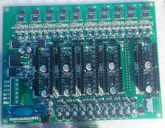
The final Decapede board samples have arrived. As soon as we verify all aspects of the board we will put it out for preorders in the hopes there is enough interest for a batch purchase!
It has a giant 1 inch, 60 Amp, blade fuse, automobile style, symbolic of its power. It has 4 ounces of copper for quality current driving and heat sinking. It has a built in micro SD, and can control 10 of everything (stepsticks, heaters, thermistors). Arduino mega compatible, and prepared for Arduino Due.
Specifications for this board can be found here: [printm3d.com]
More details soon


Sorry, only registered users may post in this forum.