Home
>
Developers
>
Topic
Dreaming of a Static Motor Arrangement and Less Vitamins
Posted by nicholas.seward
|
Dreaming of a Static Motor Arrangement and Less Vitamins April 25, 2013 03:33PM |
Registered: 10 years ago Posts: 979 |
I have been rolling around tons of ideas in my head on how to make all the steppers static and get rid of linear rails. I am positive that there is a simple solution out there that can drastically reduce the vitamin count. Rostock, RepRap Morgan, and Ultra-Bot are pretty inspiring. I love stuff about each of them but they are still using rails.
I came up with a horrible variation of a delta robot. It has an American football shaped work envelope. It also would have very limited speed. My point is not to promote this idea. My point is that this robot uses no rails and could have all the steppers in a static configuration under the build platform. It also could be fully printed barring the steppers, build platform, and extruder.
I was hoping you guys/gals could bounce some ideas (or point me to existing ones) around with me to come up with a workable alternative to linear rails that hopefully don't require moving steppers. (Requiring static mounted steppers is just a byproduct of wanting to minimize the weight of the dynamic parts.)
Ideas:
*Floating extruder supported by several wires. (I love this idea but it isn't as easy as having the wires fix a point in 3D. You have to account for all 6 DOF. There is also the additional problem that wires have to be in tension. I rate this as possible but put it on the back burner.)
*Mechanical linkage that produces straight-line motion. Hoeken's linkage would be an example. (This seems too complex to me. The main problem I have with this is that we don't need to produce straight lines to be able to accurately position something in 3D. I rate this as too complex.)
*Actuated flexible mount. Imagine a 3D McDonald's symbol with an arch every 120 degrees. You could then actuate the point where they all join by appling tension to the top or bottom of the different arches. (This one could be really neat but the response would change as the material fatigues and temp changes and ... and. You would have to have some way to measure the position of the effector at all times. I am actually okay with that. It is about time that we make a breakthrough in closed loop 3D printing. Closed loop print would also lead to cheaper electronics. Mics and DC motors could be cheaper than a stepper. Find the effector's location could be achieved with an ultra sonic emitter on the effector and a few mics scattered around on the bot to measure the phase differences. I rate this as super cool but super hard.)
*SCARA robot with a new take on the z-axis. (Looking at the lovely Morgan brings so many questions to mind. Can you make it shorter? Can you drive the arms directly without the concentric shaft? etc. I think the answer is yes for all of those. One thing that could really help is to forget about preserving the x and y location as your raise and lower the platform or raise the arms. Firmware is really good at doing math. I rate this as very promising.)
*Delta robots can already do this. (Delta robots are inherently complex. My example along with many other successful attempts have proven that this can be done. My main complaint is that the part count is high and accuracy is harder to achieve. I rate this a okay but there has to be something better.)
*etc. There are many other ideas waiting to be uncovered.
Let me know what crazy ideas you have.
I came up with a horrible variation of a delta robot. It has an American football shaped work envelope.
It also would have very limited speed. My point is not to promote this idea. My point is that this robot uses no rails and could have all the steppers in a static configuration under the build platform. It also could be fully printed barring the steppers, build platform, and extruder.I was hoping you guys/gals could bounce some ideas (or point me to existing ones) around with me to come up with a workable alternative to linear rails that hopefully don't require moving steppers. (Requiring static mounted steppers is just a byproduct of wanting to minimize the weight of the dynamic parts.)
Ideas:
*Floating extruder supported by several wires. (I love this idea but it isn't as easy as having the wires fix a point in 3D. You have to account for all 6 DOF. There is also the additional problem that wires have to be in tension. I rate this as possible but put it on the back burner.)
*Mechanical linkage that produces straight-line motion. Hoeken's linkage would be an example. (This seems too complex to me. The main problem I have with this is that we don't need to produce straight lines to be able to accurately position something in 3D. I rate this as too complex.)
*Actuated flexible mount. Imagine a 3D McDonald's symbol with an arch every 120 degrees. You could then actuate the point where they all join by appling tension to the top or bottom of the different arches. (This one could be really neat but the response would change as the material fatigues and temp changes and ... and. You would have to have some way to measure the position of the effector at all times. I am actually okay with that. It is about time that we make a breakthrough in closed loop 3D printing. Closed loop print would also lead to cheaper electronics. Mics and DC motors could be cheaper than a stepper. Find the effector's location could be achieved with an ultra sonic emitter on the effector and a few mics scattered around on the bot to measure the phase differences. I rate this as super cool but super hard.)
*SCARA robot with a new take on the z-axis. (Looking at the lovely Morgan brings so many questions to mind. Can you make it shorter? Can you drive the arms directly without the concentric shaft? etc. I think the answer is yes for all of those. One thing that could really help is to forget about preserving the x and y location as your raise and lower the platform or raise the arms. Firmware is really good at doing math. I rate this as very promising.)
*Delta robots can already do this. (Delta robots are inherently complex. My example along with many other successful attempts have proven that this can be done. My main complaint is that the part count is high and accuracy is harder to achieve. I rate this a okay but there has to be something better.)
*etc. There are many other ideas waiting to be uncovered.
Let me know what crazy ideas you have.
|
Re: Dreaming of a Static Motor Arrangement and Less Vitamins April 25, 2013 07:15PM |
Registered: 11 years ago Posts: 374 |
|
Re: Dreaming of a Static Motor Arrangement and Less Vitamins April 25, 2013 09:46PM |
Registered: 10 years ago Posts: 979 |
Cheapskate requires quite a few vitamins. I am dreaming of printing everything but the motors, build plate, and the extruder. Why not have the steppers snap in instead of using screws? Etc.
I really have no problem with linear motion (Linear motion is great. There is a reason it is so prevalent.) other than that it requires a lot of vitamins. Additionally, innovations can come from evolution or revolution. Evolution has the benefit of pulling the best of what has come before to make an incrementally better machine. Revolution has the benefit of opening up avenues that evolution ignores. (I think mutation is a good analogy.) I am quite sure the first machine I build that has no linear motion will be less capable than the status quo. However, lessons will be learned and added to the collective knowledge. Those evolutionary machines can then take the good ideas and leave the bad ones.
I really have no problem with linear motion (Linear motion is great. There is a reason it is so prevalent.) other than that it requires a lot of vitamins. Additionally, innovations can come from evolution or revolution. Evolution has the benefit of pulling the best of what has come before to make an incrementally better machine. Revolution has the benefit of opening up avenues that evolution ignores. (I think mutation is a good analogy.) I am quite sure the first machine I build that has no linear motion will be less capable than the status quo. However, lessons will be learned and added to the collective knowledge. Those evolutionary machines can then take the good ideas and leave the bad ones.
|
Re: Dreaming of a Static Motor Arrangement and Less Vitamins April 26, 2013 12:32AM |
Admin Registered: 13 years ago Posts: 730 |
The "Rep" in RepRap stands for "Replicating", and don't let anyone tell you different, Nicholas!  It even says on the front page of reprap.org: "RepRap is humanity's first general-purpose self-replicating machine."
Folks who just want to build a "Rap" should by all means follow crispy1's advice and get some off-the-shelf linear rail.
Those truly interested in the "Rep" part (and I hope there will always be at least a few of us) will appreciate your ideas. This topic comes up occasionally on the forum, and it has been hashed over a good amount in other threads. For example, see this one.
I really like the RepRap Morgan, as well as its predecessors (some of which are discussed in this thread. I think a nice way to go "linear-free" would be to add a linkage-driven vertical axis to the build platform for a parallel SCARA. Something like this:
Sarrus L04
If you haven't seen it, you might also like this product of genius and/or insanity.
There are a lot of other "printable linear bearing" type projects around. A few examples:
Printable X/Y Sarrus Linkage
Printable X/Y Linear Rail
Compliant Linear Motion Mechanism
But why stop at printing your own mechanics? Why not go ahead and print the motors and extruder too? A few attempts in that direction:
Printable solenoid motor
Printable flat coil motor
Electroformed Nozzle
A final question: in your Delta design, why are the motor rotation axes normal to the base plate? Why not arrange them the "regular way" like in the Yazzo Polybot.
It even says on the front page of reprap.org: "RepRap is humanity's first general-purpose self-replicating machine."Folks who just want to build a "Rap" should by all means follow crispy1's advice and get some off-the-shelf linear rail.
Those truly interested in the "Rep" part (and I hope there will always be at least a few of us) will appreciate your ideas. This topic comes up occasionally on the forum, and it has been hashed over a good amount in other threads. For example, see this one.
I really like the RepRap Morgan, as well as its predecessors (some of which are discussed in this thread. I think a nice way to go "linear-free" would be to add a linkage-driven vertical axis to the build platform for a parallel SCARA. Something like this:
Sarrus L04
If you haven't seen it, you might also like this product of genius and/or insanity.
There are a lot of other "printable linear bearing" type projects around. A few examples:
Printable X/Y Sarrus Linkage
Printable X/Y Linear Rail
Compliant Linear Motion Mechanism
But why stop at printing your own mechanics? Why not go ahead and print the motors and extruder too? A few attempts in that direction:
Printable solenoid motor
Printable flat coil motor
Electroformed Nozzle
A final question: in your Delta design, why are the motor rotation axes normal to the base plate? Why not arrange them the "regular way" like in the Yazzo Polybot.
|
Re: Dreaming of a Static Motor Arrangement and Less Vitamins April 26, 2013 09:07AM |
Registered: 12 years ago Posts: 313 |
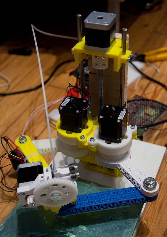
I designed this low vitamin parallel SCARA printer a while back. The current version looks about the same, but it has a printed frame and a bowden extruder. It's not really ready for prime time, the periodic errors in the drive mechanism, with worst case amplitude of almost 1 mm in xy, make it currently a curiosity instead of a general use printer.
The sources for the latest stable version are here.
I'm currently redesigning this, I believe (hope) that I now know what to do differently to make this a working, general use printer.
One thing I was considering was getting rid of the Z rails and screw: making the XY motors static and changing the build platform to move in Z. If it was possible to do the Z movement with printed parts, then this design could achieve a very low vitamin count.
What are the options of implementing the build platform Z movement with printed parts? In this application, it would have to be something that doesn't extend above the platform or below the bottom of the printer. Something that goes from 100 mm to 200 mm would probably be good enough. Sarrus linkages look promising, but they are just for constraining the motion, not producing it.
|
Re: Dreaming of a Static Motor Arrangement and Less Vitamins April 26, 2013 09:45AM |
Registered: 10 years ago Posts: 979 |
@MattMoses
Great Stuff. I have read through a lot of that stuff. Somehow the printed x/y rail escaped me. Very cool.
My delta design was something that I had to get out of my head. You know those ideas that you get that you know are probably bad but you have to address them anyways. My thought was that mounting of arms and motors could be easier if that all occupied the same plane. Additionally, you could make the bottom arms curved and this could fold in to make a pretty compact package. It obviously has 3 major problems: complexity, speed, and strange less than useful work envelope. Now my brain is rid of the idea so I can move on. (Additionally, I have decided that I don't want a moving build plate. To do extreme prints it seems that you can only get away with having a build plate that moves in the z. Since I want to get rid of linear motion if possible; a slow moving, powerful, uncoupled z axis is probably out of the question.)
@ttsalo
That is a great design. The world doesn't utilize planetary gears enough. I will bounce around a few ideas in my head to Make a SCARA linear free. SCARA-bots seems to be taking an early lead in my head.
|
Re: Dreaming of a Static Motor Arrangement and Less Vitamins April 26, 2013 10:09AM |
Registered: 12 years ago Posts: 313 |
Googled a bit and and I bet this could be printed: Rigid chain actuator
Together with Sarrus linkages or similar this could allow printing a Z movement mechanism which goes really flat in the lowest position.
BTW, the arm actuators in the SCARA design are harmonic drives, not planetary gears.
Edited 1 time(s). Last edit at 04/26/2013 10:10AM by ttsalo.

Together with Sarrus linkages or similar this could allow printing a Z movement mechanism which goes really flat in the lowest position.
BTW, the arm actuators in the SCARA design are harmonic drives, not planetary gears.
Edited 1 time(s). Last edit at 04/26/2013 10:10AM by ttsalo.
|
Re: Dreaming of a Static Motor Arrangement and Less Vitamins April 26, 2013 10:49AM |
Registered: 10 years ago Posts: 979 |
I should have caught that. Harmonic is a much better pick for this application. The world also needs more Harmonic Drives! 
I have never seen a actuator like that. I am sure a plastic version can be made.
For a simple solution, the z-ish axis could a platform with four(three would be enough) longish parallel bars connected to all the corners. These bars could be perpendicular to the z for the middle of the work envelope. A string would be all that is needed to lower the platform. @Professional RepRappers: Do any printing operations result in a net upward force on the platform?
I am starting to get an interesting design in my head of a SCARA variant. I will CAD it up and post it to get some feedback.
|
Re: Dreaming of a Static Motor Arrangement and Less Vitamins April 26, 2013 12:57PM |
Registered: 11 years ago Posts: 40 |
|
Re: Dreaming of a Static Motor Arrangement and Less Vitamins April 28, 2013 05:09PM |
Registered: 12 years ago Posts: 17 |
That RepRap Morgan is brilliant.
Regarding 3D printers that are as nearly self-replicating as possible, requiring as few vitamin parts as possible, I'm interested in technological bootstrapping going right back to wood, clay, rocks and metal ore.
To begin with I'm trying to work out whether it's practical to make a 3D printer where the only vitamin parts are copper wire, soft-iron rods (e.g. nails), and a pre-built hot end, and the only assembly processes are ones that are reasonable for one human to do in a short time, perhaps with assistance from machines that the 3D printer can make. So winding electromagnets (the 3D printer could print a winding machine to help with that), and assembling the printer are both reasonable for one human, but making a fully functional semiconductor fab completely from scratch is not (not yet at least). Matt described a challenge a lot like this in another topic: VORBAT
The problems include:
I think a good starting point is to demonstrate the feasibility of the control circuit by making it with off-the-shelf relays. The electromechanical computing machines that operated from the 1930s to the 1960s had operating speeds of tens of Hertz, though I don't know whether it would be possible to get up to that speed with nail-and-wire relays.
Regarding 3D printers that are as nearly self-replicating as possible, requiring as few vitamin parts as possible, I'm interested in technological bootstrapping going right back to wood, clay, rocks and metal ore.
To begin with I'm trying to work out whether it's practical to make a 3D printer where the only vitamin parts are copper wire, soft-iron rods (e.g. nails), and a pre-built hot end, and the only assembly processes are ones that are reasonable for one human to do in a short time, perhaps with assistance from machines that the 3D printer can make. So winding electromagnets (the 3D printer could print a winding machine to help with that), and assembling the printer are both reasonable for one human, but making a fully functional semiconductor fab completely from scratch is not (not yet at least). Matt described a challenge a lot like this in another topic: VORBAT
The problems include:
- - Making a 3D printable tape reader for reading printed plastic tape - the tape with the encoding on must also be printable.
- Controlling a stepper motor reasonably quickly using relays.
- Making adequate stepper motors using only nails and copper wire.
- Making reliable and fast relays using nails and copper wire. (off-the-shelf relays have an operating time of around 1 millisecond).
- Working out a suitable electromechanical control circuit for the printer. It must operate quickly, and must operate from an encoding of objects on the tape that is possible for humans to understand and write, and which keeps the tape length short. It need not necessarily be a Turing-complete computer, it could just be a circuit that converts from some compact encoding to a sequence of signals to feed to stepper motors. Here is an outline of an idea about how this could be done (I hope it is intelligible):
VORBAT controller idea
I think a good starting point is to demonstrate the feasibility of the control circuit by making it with off-the-shelf relays. The electromechanical computing machines that operated from the 1930s to the 1960s had operating speeds of tens of Hertz, though I don't know whether it would be possible to get up to that speed with nail-and-wire relays.
|
Re: Dreaming of a Static Motor Arrangement and Less Vitamins April 29, 2013 04:49AM |
On the less vitamins note I am working on a prusa i3 printable frame. I am putting actual engineering into this. I am still going back and forth on whether to tension set it or nut/bolt set it. I will probably do a few tes prints on the 2 joint ideas I have and then decide.
I am going to integrate the z axis motor mounts onto the printed frame.
I will be doing some strength testing on two frame ideas I have as soon as I catch up on sleep. (working graveyard shift at the moment and had some things that required my attention mid day the last 2 weeks)
One is an intersecting double tube. All of the round shaping in this makes it very strong and resistent to multidirectional force, the issue is a lot of printers can't handle rounds that well. This version is unrealistic unless your printer is very well calibrated, or you are using water soluable supports.
the other is a hollow 60mm cube with an internal pyramid mesh. I am starting to think I may have gone overkill with my current design on this and I may back off a bit on the 60mm sizing. I am also still thinking of the best way to print / attach the 4 pieces to avoid layer adhesion breakage. This is of most worry on the bed attachement area, since I have 2 pieces intersecting there as well as the bed attaching.
I will keep plugging away in CAD until I think it's ready for a test print. I will releast STL's and SCAD code for it then, and we can all start tweaking it.
|
Re: Dreaming of a Static Motor Arrangement and Less Vitamins April 29, 2013 04:51AM |
|
Re: Dreaming of a Static Motor Arrangement and Less Vitamins April 29, 2013 10:58AM |
Registered: 10 years ago Posts: 979 |
I understand why most don't print the frame. It would take a very long time. I think for most the cost of components is less than the printer time is worth to them. That said, I think we need some well engineered printable frames to give people the option to reduce the vitamin count.
What I don't understand is why is pvc pipes underutilized. It seems like we could replace aluminum extrusions and threaded rods at a fraction of the cost. That said, I understand that pvc is still a vitamin.
What I don't understand is why is pvc pipes underutilized. It seems like we could replace aluminum extrusions and threaded rods at a fraction of the cost. That said, I understand that pvc is still a vitamin.
|
Re: Dreaming of a Static Motor Arrangement and Less Vitamins April 30, 2013 02:19PM |
Registered: 11 years ago Posts: 381 |
The only problems with the : Rigid chain actuator if I remember right. Is that it has really tight tolerances and requires a lot of stregnth in the parts that make up the sum. If it could be simplified in build and manufacturing you would be on course for a promising build. Taking that concept and applying it to four corners making up the z axis of a reprap would make it more compact, easy shipping, stronger and almost limitless as far as z height. That's definatly an idea that someone should run with. You could build the X & Y axis into the top of the platform and move the whole top up as it prints.
@ nicholas.seward - You are on the right track of thinking. Less vitamins and more printed parts should be the natural direction of the reprap industry. Unfortunately most companies are moving toward laser cut parts due to manufacturing costs and away from the plastic that started all of this. Good work guys!! Keep going in the direction your on and I suspect I will see great things. Thanks for re-focusing my attention to what repraps are all about.
--------------| For Everything |--------------------------
Check it out here:
[reprapsquad.wordpress.com].
---------| For Everything Prototype Related |------
Now featuring comp case mods:
[RepRapLab.wordpress.com]
--------------| Find us at Twitter|------------------------
@REPRAPSQUAD (RS Main)
[mobile.twitter.com]
@REPRAPSQUADHQ (ProtoLab)
[mobile.twitter.com]
|
Re: Dreaming of a Static Motor Arrangement and Less Vitamins May 01, 2013 10:18PM |
Registered: 16 years ago Posts: 174 |
@WillStevens
I'd try to stay away from printing the tape, storing a long length of rigid plastic tape is going to be difficult. It might be better just to use paper tape instead.
If you are using relays that operate at ~1 Hz it might make more sense to move to fluidics which can operate at 10s of Hz easily. Fluidics are also a bit easier to print than relays as one doesn't require nails or copper wire. It's also relatively easy to print actuators with fluidics, especially if you can print silicone elastomer. Sensors are easy too, a fluidic tape reader is simply a row of nozzles directed at pipes.
Your VORBAT controller is almost exactly what early CNC machines used. You could probably implement it fluidically, perhaps something like this: [www.google.com]
|
Re: Dreaming of a Static Motor Arrangement and Less Vitamins May 02, 2013 11:20AM |
Registered: 11 years ago Posts: 205 |
REPRAP SQUAD Wrote:
-------------------------------------------------------
> The only problems with the : Rigid chain actuator
> if I remember right. Is that it has really tight
> tolerances and requires a lot of stregnth in the
> parts that make up the sum. If it could be
> simplified in build and manufacturing you would be
> on course for a promising build. Taking that
> concept and applying it to four corners making up
> the z axis of a reprap would make it more compact,
> easy shipping, stronger and almost limitless as
> far as z height. That's definatly an idea that
> someone should run with. You could build the X & Y
> axis into the top of the platform and move the
> whole top up as it prints.
This actuator (called linklift) cannot be simplified, it works because of the tight tolerances. It is also heavy duty system designed to handle tons, like whole theater scenes. up to 15 tons & 20 meters height at 300 mm/s per column. A bit oversized perhaps no ?
There is another product, rigibelt that could fit the need, 2 timing belts with blocks that lock themselves like a pant zipper to form a solid column but it is patented, and again the precision for a system sized to our needs is too high.
The assembling/desassembling box is also quite complex.
But a poor man version with simple rectangular blocks not interlockings but resting on the previous one could work, the load is very small and the blocs could be printed. That would need lots of blocks though
|
Re: Dreaming of a Static Motor Arrangement and Less Vitamins May 03, 2013 07:16PM |
Registered: 12 years ago Posts: 17 |
@Gene Hacker
Thanks for the fluidic actuator patent link. I am interested in the possibility of using fluidic control, and also purely mechanical logic using solid parts.
The reason that I think that relays are more feasible (in the short term) is that there is already a lot of work on making reliable and fast (10s of Hertz) relay circuits, so controlling a reprap using off-the-shelf relays is something that could probably be done right now. As far as I know nobody has built any complex control circuit using fluidics (but please post details if you know otherwise). It will be necessary to work out how to make large, fast, reliable fluidic logic circuits first (something I'm currently investigating Fluidic Logic Circuit), before using them to control a RepRap.
Regarding mechanical logic, I think the most complex non-eletromechanical digital computer to date is Zuse's Z1. According to Zuse it didn't work reliably. A RepRap controller probably wouldn't need to be as complex as the Z1, although it might need to be faster.
Do you have references & circuit diagrams for the early CNC machines you mention? - I'd be really interested in finding out more about those.
The plastic instruction tape would not need to be all one piece. It could fold like in the Jacquard loom ( Jacquard Loom ) and player pianos, or a system of cards could be used, like in punched card computers where a deck cards was used to store a sequence of instructions ( Punched Cards ). Even if it was all one piece, a single layer of printed plastic is flexible enough to be rolled up into a roll with an inner diameter not much larger than a toilet roll inner, see photo showing flexibility of single layer: Flexible single 0.4mm (ish) layer of PLA .
|
Re: Dreaming of a Static Motor Arrangement and Less Vitamins May 04, 2013 05:03AM |
Registered: 12 years ago Posts: 1,236 |
Here is a an early CNC machine:
I don't like to pour cold water on what might a fun project with a somewhat steampunk flavor, but I have to say it is unlikely to lead to any practical results. Even a "simple" microcontroller like an AVR probably has in the region of 100,000 transistors.
There is good reason why electromechanics were replaced with electronics, electronics makes things possible that are otherwise effectively impossible. Machines like RepRap are only made possible through the use of very high tech - silicon chips with nanometer scale features made in billion dollar fabs.
If you are talking about only using low tech, then I think you have to keep an eye on the goal, which is to fashion an object out of some material. If you have the tools to build an electromechanical printer, it would be quicker and cheaper to use those tools to build the objects directly.
So that presents a conundrum - to make a home 3d printer it requires technology that cannot be made on a home printer. Removing the high tech part makes the printer not worth the cost of creation.
|
Re: Dreaming of a Static Motor Arrangement and Less Vitamins May 04, 2013 08:00AM |
@REPRAP SQUAD - The thing is right now manufacturors are going to Lasercutting/CNC to save money. When prices on filament drop or we get consistent pellet based extruders, a printed frame will cost $3 -$4 (current weight on my i3 frame is 3.3 pounds)
@ tssalo - You CAN getthe Z easily taken care of with less vitamins. Why not use a setup like a car jack? with the motor mounted on one side driving a threaded rod, you could eliminate the smooth rods for bed movement. All of the pins COULD be done in plastic as well. The nuts would have to be a tight fit in their retention plates so you wouldn't have lash but it's totally doable.
@ tssalo - You CAN getthe Z easily taken care of with less vitamins. Why not use a setup like a car jack? with the motor mounted on one side driving a threaded rod, you could eliminate the smooth rods for bed movement. All of the pins COULD be done in plastic as well. The nuts would have to be a tight fit in their retention plates so you wouldn't have lash but it's totally doable.
|
Re: Dreaming of a Static Motor Arrangement and Less Vitamins May 05, 2013 12:35PM |
@bobc
There is the practical goal of making a cheap, autonomous, and versatile personal manufacturing system. If that is the objective then the number of vitamin parts and the complexity of the machine and its control system are irrelevant unless they affect the price and performance of the machine, and the range of people who have access to it.
The self-replicating or closed-cycle manufacturing system goal is a separate one (but with some overlaps in the realisation), which may or may not turn out to be feasible or useful, but I find it interesting from a pure science perspective regardless of whether it is useful or not. For this goal, the number of vitamin parts, and the complexity of construction of both the mechanical part of the machine and the control system are fundamental considerations. There are reprappers who are interested in one or the other or both of these goals (I'm interested in both).
|
Re: Dreaming of a Static Motor Arrangement and Less Vitamins May 05, 2013 06:40PM |
Registered: 12 years ago Posts: 1,236 |
OK, I sort of see your argument. I have a belief that technological primitivism, like social primitivism, is not viable. In other words, complexity is like an arrow that allows us to move forwards, but not backwards. It is kind of tied to Joseph Tainter's theories in "The Collapse of Complex Societies". I can't prove any of that, but I could be proved wrong.
If anything is likely to create self-replicating machines, I think it is likely to be genetic engineering, but that is decidedly high-tech.
Anyway, assuming that the printer runs something like Gcode on punched tape or card, is a PC still required to design the 3D model and slice the STL and generate Gcode?
|
Re: Dreaming of a Static Motor Arrangement and Less Vitamins May 05, 2013 10:15PM |
Registered: 16 years ago Posts: 174 |
@WillStevens depends on what you mean by complex circuits.
Back when relay computers were common, UNIVAC built a simple completely fluidic computer called the FLODAC:
dl.acm.org/ft_gateway.cfm?id=1464112&type=pdf
NASA investigated making some fluidic stepper motors for actuating stuff inside the high radiation environment of a NERVA engine. It also has some nice info on designing fluidic integrated circuits:
[www.scribd.com]
[www.scribd.com]
Fluidics has been used in various aerospace systems, so it can be made fairly reliable, but achieving this at the amateur scale might be difficult. I will admit fluidics is fairly esoteric, even more so than relay logic. One certainly can't pick up a fluidic pressure/current meter at a local Radioshack. Though the large reduction in vitamins does make this direction rather tempting...
The fluidic logic circuits are quite unconventional, most fluidic devices are based around the fluidic amplifier:
[miriam-english.org]
As far as early CNC machines go, here's some patents for the first CNC machine:
[www.google.com]
[www.google.com]
Here's an article in scientific american explaining the same thing:
[blog.modernmechanix.com]
It was servo/selsyn motor actuated though, so I suspect building a more modern controller would be a bit different.
And here's a more advanced one:
[www.google.com]
Now on the issue of tape: converting these files for reprap wallace [www.thingiverse.com] to gcode using Slic3r, I get a gcode file that is 315 kb in size. Assuming we can convert file size directly to tape and standard 7 bit tape with a hole spacing of 0.1 inches. We get a tape ((315 kilobytes) / (7 bits)) * 0.1 inches = 0.9363456 kilometers long. Using this online calculator here [www.handymath.com] to figure out roll diameter, and assuming an inner diameter of 1.5"(toilet paper tube), we get a roll diameter of ~ 70 centimeters(~2.25 feet). So I guess this would be reasonable in terms of storage.
|
Re: Dreaming of a Static Motor Arrangement and Less Vitamins May 06, 2013 12:54AM |
Registered: 16 years ago Posts: 174 |
The only reason for using primitive technology like fluidics or relay computers is because they are easy to replicate. It'd be pretty hard to produce our own microchips without a "billion dollar fab."
Sure a reprap constructed with relays/fluidics may be slow, it may be inefficient, but the point is it will replicate.
One will still need a pretty advanced computer to generate the paper tape, but one needn't use punched tape for data storage and control. One could emulate the tape drive with a computer controlled device. One way you could do this with fluidics would be to make an array of fluidic tone detectors(one for each hole in the tape) that 'listen' to some sort of sound output device and in place of the tape advance mechanism one simply puts a 'whistle'. This way when you put a smart phone with its speaker up against the tone detectors and its microphone to the whistle, it plays several tones together that represent the holes on the tape and whenever the 'whistle' receive a pulse the smartphone microphone detects this and 'advances the tape.'
You could use the whole thing as part of a "RepRap Starter Edition," it may not be the best, fastest, most efficient way of going, but it'll get you going so you can make parts to sell/buy upgrades.
Aside from that, the way reprap's controllers are currently set up, we essentially have a very fancy "tape reading machine" albeit one that uses SD cards in place of paper tape. We aren't even implementing G-code commands for drawing arcs and curves. This NC machine from 1956 probably implements all the G-code commands we really need.
My main impetus for going with fluidics, relays, and other minimalistic control systems is that I'm interested in making a completely self-replicating system. So far, simple self-replicating systems have been made that self-assemble themselves from discrete parts. I think that the next step towards making a self-replicating system is to make a self-replicating system "toy model" capable of manufacturing most of its own parts from preprocessed materials like plastic filament, nails, resin, wire, etc. Making (fast) transistors is simply out of the scope of such a "toy model."
|
Re: Dreaming of a Static Motor Arrangement and Less Vitamins May 06, 2013 12:39PM |
Registered: 11 years ago Posts: 490 |
I think mechanically, RepRap is capable of much more than what we usually make right now. The various SCARA projects are a testament for this.
A robot arm (4 axis?) might require the least vitamins. While trying to source parts for my own (conventional, cartesian) printer, I came across this interesting design from Igus. Since it is driven with bowden cables by motors sitting somewhere at the base, the moving parts can be kept extremely lightweight and all the required vitamins might be reduced to dyneema lines, PTFE tubes, bearings (although they might be substituted with printed Nylon bushings), screws, motors and electronics.
To achieve the high resolution needed for precisely positioning the nozzle, one could use herringbone gears similar to the ones being used for some extruders. The required stiffness might be achieved by using PC or an efficient form of infill.
Another advantage is that the theoretical print volume is greater than the printer itself. I can imagine arranging multiple print beds around the arm.
|
Re: Dreaming of a Static Motor Arrangement and Less Vitamins May 08, 2013 01:56AM |
Admin Registered: 13 years ago Posts: 730 |
Quote
Gene Hacker
Now on the issue of tape: converting these files for reprap wallace [www.thingiverse.com] to gcode using Slic3r, I get a gcode file that is 315 kb in size. Assuming we can convert file size directly to tape and standard 7 bit tape with a hole spacing of 0.1 inches. We get a tape ((315 kilobytes) / (7 bits)) * 0.1 inches = 0.9363456 kilometers long. Using this online calculator here [www.handymath.com] to figure out roll diameter, and assuming an inner diameter of 1.5"(toilet paper tube), we get a roll diameter of ~ 70 centimeters(~2.25 feet). So I guess this would be reasonable in terms of storage.
This estimate seems high. Correct me if I'm wrong, but the gcode file is probably in plain text format, so each *character* in the gcode takes 8 bits (1 byte) to store. If we use a custom encoding, we don't need that many bits to store a single gcode command.
A quick way to estimate a lower bound on tape size would be to count the number of lines in your gcode file (i.e. the number of commands) and then make a wild guess about how much it takes to store a single command. Will's proposed encoding uses 32 bits (4 bytes) per command (or 24 bits (3 bytes) if only the X and Y axes are commanded).
A typical line of gcode from a slicer (typical according to this page anyway) like this
N7 G1 X2.0 Y2.0 F3000.0*85takes up 208 bits (26 bytes) in a plain text file (or more if you count end-of-line characters), but using Will's scheme it could be stored in 24 bits (3 bytes). You won't get error correction, and the resolution and maximum travel distance will be limited, but we can live with those limitations.
Another way to save space is by carefully designing the parts so they make heavy use of repeated layers. This was brought up in the VORBAT thread. Many of the Wallace parts, for example, could be made by repeating a few different layer patterns over and over. Then you only need to store one tape per unique layer, and another tape that has the order in which layers should be deposited.
PS - I know we all know the difference between a "bit" and a "byte" but when doing calculations like this it is easy to get the units scrambled up - that's why I was explicit with the "bits (bytes)" notation.
|
Re: Dreaming of a Static Motor Arrangement and Less Vitamins May 08, 2013 07:06AM |
Registered: 12 years ago Posts: 17 |
@bobc
I've no answer to the question of how to produce the punched tape without an electronic computer. Maybe it will be possible to come up with a machine to make tracing out paths by hand and punching them onto tape less time-consuming. Perhaps if objects are designed and represented slice-by-slice from the outset (rather than as 3D models in STL files) then generating a path from a slice would fall within the scope of what a relay computer is capable of doing in a few hours of operation.
I think the whole question of construction complexity is very interesting - given a target object X, what starting materials (be they raw materials or pre-fabricated vitamin parts), manufacturing processes, human involvement and time is needed to make object X (obviously there is no single answer - if you are willing to allow a long enough time then you can make some things by gluing small particles together under a microscope). For a given set of starting materials, how many 'generations' removed is object X from the starting materials - e.g. maybe you first have to make tools, and use those tools to make other tools which then make the final object.
It seems to me that the way our technology normally develops means that there is not much direct incentive to work out and write down what the construction complexity of an object actually is, and whether the construction complexity and the number of generations between a useful object (a silicon chip say) and its raw materials can be reduced. The only thing that matters to chip producers (quite reasonably) is cost and performance.
|
Re: Dreaming of a Static Motor Arrangement and Less Vitamins May 08, 2013 10:21AM |
Admin Registered: 13 years ago Posts: 730 |
There was interesting article about the construction complexity of microchips, from the standpoint of environmental impact. It was a lot of work for the authors just to estimate the materials input for the microchip - let alone the materials to make the machines that make the microchips!
The link is unfortunately behind a paywall, but you can find the pdf by searching around:
The 1.7 Kilogram Microchip: Energy and Material Use in the Production of Semiconductor Devices
E.D. Williams, R.U. Ayres, M. Heller
[pubs.acs.org]
The link is unfortunately behind a paywall, but you can find the pdf by searching around:
The 1.7 Kilogram Microchip: Energy and Material Use in the Production of Semiconductor Devices
E.D. Williams, R.U. Ayres, M. Heller
[pubs.acs.org]
Quote
Abstract
The scale of environmental impacts associated with the manufacture of microchips is characterized through analysis of material and energy inputs into processes in the production chain. The total weight of secondary fossil fuel and chemical inputs to produce and use a single 2-gram 32MB DRAM chip are estimated at 1600 g and 72 g, respectively. Use of water and elemental gases (mainly N2) in the fabrication stage are 32000 and 700 g per chip, respectively. The production chain yielding silicon wafers from quartz uses 160 times the energy required for typical silicon, indicating that purification to semiconductor grade materials is energy intensive. Due to its extremely low-entropy, organized structure, the materials intensity of a microchip is orders of magnitude higher than that of “traditional” goods. Future analysis of semiconductor and other low entropy high-tech goods needs to include the use of secondary materials, especially for purification.
|
Re: Dreaming of a Static Motor Arrangement and Less Vitamins May 08, 2013 03:26PM |
Registered: 12 years ago Posts: 1,236 |
MattMoses Wrote:
-------------------------------------------------------
> There was interesting article about the
> construction complexity of microchips, from the
> standpoint of environmental impact. It was a lot
> of work for the authors just to estimate the
> materials input for the microchip - let alone the
> materials to make the machines that make the
> microchips!
>
> The link is unfortunately behind a paywall, but
> you can find the pdf by searching around:
That is interesting, and from a sustainability point of view quite scary. I work for a company that provides products to the major semicon fabs and its a big chunk of the companies revenue. Some of the chemicals they use in semi are pretty nasty, highly toxic and highly flammable.The maintenance guys have to be very careful.
I do wonder how we can maintain this sort of activity in the long term, I don't just mean maintaining progress, but just staying at the level we are. I am not a "doomer", but there is a strong argument to suggest that industrial society is only enabled by the availability of cheap energy, and that is running out... amongst a whole host of other sustainability problems - climate, water, fishing stocks, mineral resources, environmental depletion, antibiotic resistance. If current civilisation is to survive for thousands or even hundreds more years then humans will have to get a lot smarter. The alternative is going back to pre-industrial times, which were not as idyllic as sometimes painted.
Anyway, I digress! I have been researching relay logic:
- A 4-Bit Counter Using Relays requires 19 relay elements, about 5 per bit.
- a simple 8 bit CPU Relay Computer Two uses 281 relays
- Harry Porter's Relay Computer a larger CPU has over 400 relays, surprisingly uses only 160W.
- switch speed of relay systems is a lot slower than electronics, but may still be quite nippy as shown here [www.youtube.com]
- I have 30 spare relays from work, I might put them to use by building a counter. I found some surplus relays on sale at 40p each, so would cost in the region of £110 to build the 281 relay CPU. I think I would only build that if I can get more relays for ~ 20p each.
Also, other fans of retro-computing (as I am) might be interested in [Plan28.org] - a project to create Babbage's Analytical engine.
-------------------------------------------------------
> There was interesting article about the
> construction complexity of microchips, from the
> standpoint of environmental impact. It was a lot
> of work for the authors just to estimate the
> materials input for the microchip - let alone the
> materials to make the machines that make the
> microchips!
>
> The link is unfortunately behind a paywall, but
> you can find the pdf by searching around:
That is interesting, and from a sustainability point of view quite scary. I work for a company that provides products to the major semicon fabs and its a big chunk of the companies revenue. Some of the chemicals they use in semi are pretty nasty, highly toxic and highly flammable.The maintenance guys have to be very careful.
I do wonder how we can maintain this sort of activity in the long term, I don't just mean maintaining progress, but just staying at the level we are. I am not a "doomer", but there is a strong argument to suggest that industrial society is only enabled by the availability of cheap energy, and that is running out... amongst a whole host of other sustainability problems - climate, water, fishing stocks, mineral resources, environmental depletion, antibiotic resistance. If current civilisation is to survive for thousands or even hundreds more years then humans will have to get a lot smarter. The alternative is going back to pre-industrial times, which were not as idyllic as sometimes painted.
Anyway, I digress! I have been researching relay logic:
- A 4-Bit Counter Using Relays requires 19 relay elements, about 5 per bit.
- a simple 8 bit CPU Relay Computer Two uses 281 relays
- Harry Porter's Relay Computer a larger CPU has over 400 relays, surprisingly uses only 160W.

- switch speed of relay systems is a lot slower than electronics, but may still be quite nippy as shown here [www.youtube.com]
- I have 30 spare relays from work, I might put them to use by building a counter. I found some surplus relays on sale at 40p each, so would cost in the region of £110 to build the 281 relay CPU. I think I would only build that if I can get more relays for ~ 20p each.
Also, other fans of retro-computing (as I am) might be interested in [Plan28.org] - a project to create Babbage's Analytical engine.
|
Re: Dreaming of a Static Motor Arrangement and Less Vitamins May 08, 2013 04:22PM |
Registered: 12 years ago Posts: 23 |
Vitamins are vital, but too much vitamins are normally the orange stuff you see in the boal after the morning tea has worked itself though your system. I believe it should be the same for Reprap machines.
I tried my best to get to some kind of arrangement that would solve the need for linear rails in Morgan, but just could not get something stable enough to serve the purpose. The least amount of rails became my next goal, and it is safe to say that number is two. One advantage of using it on Z is that it does not need to be machined, and you actually don't need to use bearings. Z-movements are not as fast or repetitive as cartesian X and Y movements, in other words, bushings would do just fine if spaced correctly. That means that standard smooth bright steel rods would be sufficient, if you maintain the finish with a thin layer of vaseline every now and again.
That said, there are already a couple of ideas rolling around in my head for upgrades to Morgan, or a possible successor. I'll be keeping my eyes open, and ears on the ground for solutions to these problems...
Cheers,
Quentin
PS: If any of you are in Gauteng next week, come join us at House for Hack in Centurion next Tuesday. The new Morgans will be there, and I will be pushing my Morgan plans to git. Time for Morgan to go Wild
|
Re: Dreaming of a Static Motor Arrangement and Less Vitamins May 08, 2013 04:38PM |
Registered: 10 years ago Posts: 979 |
@qharley: I wish I was going to be in Gauteng. I am in the middle of nowhere USA. Great work on your project. Without people pushing the envelope, life would be pretty boring.
Check out http://forums.reprap.org/read.php?178,206458 if you get a chance. It has a long way to go before it can be printed but it is Morgan-inspired even if it doesn't look like it. I have been meaning to ask you how you put together your tool holder. For demonstration purposes I threw a Ubis hotend in the design but it is very evident that the design would benefit from a shorter hot end. I eagerly await May 14th to be able to dig through your plans.
Thanks,
Nick

Sorry, only registered users may post in this forum.