Dreaming of a Static Motor Arrangement and Less Vitamins
Posted by nicholas.seward
|
Re: Dreaming of a Static Motor Arrangement and Less Vitamins May 08, 2013 08:54PM |
Registered: 11 years ago Posts: 381 |
This is the start and you will be the founders of Sky net. Be forewarned.
--------------| For Everything |--------------------------
Check it out here:
[reprapsquad.wordpress.com].
---------| For Everything Prototype Related |------
Now featuring comp case mods:
[RepRapLab.wordpress.com]
--------------| Find us at Twitter|------------------------
@REPRAPSQUAD (RS Main)
[mobile.twitter.com]
@REPRAPSQUADHQ (ProtoLab)
[mobile.twitter.com]
|
Re: Dreaming of a Static Motor Arrangement and Less Vitamins May 14, 2013 12:35PM |
Admin Registered: 13 years ago Posts: 730 |
On relay computers: don't forget the TIM8. It even has a tape reader! TIM8 is incredibly entertaining to watch in action.
Here it computes the answer to life, the universe, and everything.
And here it plays Mary had a Little Lamb using a relay-driven soundcard.
Yes, a relay-driven soundcard:
Here it computes the answer to life, the universe, and everything.
And here it plays Mary had a Little Lamb using a relay-driven soundcard.
Yes, a relay-driven soundcard:
Quote
from the video
Now it's always interesting to see if it works, because relays aren't designed to switch on and off at five thousand times a second. It can jam... occasionally. I wanted to make this video before it burned out entirely.
|
Re: Dreaming of a Static Motor Arrangement and Less Vitamins May 14, 2013 05:59PM |
Registered: 12 years ago Posts: 17 |
All those relay computer links are really interesting. I like the 2-relay toggle flip flop design in the 4-bit counter paper that bobc posted (it uses some relay behaviour that I hadn't ever thought about) and the efficient register design in the TIM8 with 1 relay per bit. I'm on the look out for old books and references about relay circuit design. I remember reading somewhere that in some relay computers, if you held a relay open by jamming a screwdriver in it, the whole computer would halt and wait for you to remove it before continuing. Also I think some designs were 'spark free', so that when contacts opened and closed there was no sparking, so contacts lasted longer.
I've just bought 100 relays to mess around with, beginning with trying to make a stepper motorindexer driver with direction and pulse inputs, and four outputs, using the minimum number of relays.
Edited 1 time(s). Last edit at 05/15/2013 08:34AM by WillStevens.
I've just bought 100 relays to mess around with, beginning with trying to make a stepper motor
Edited 1 time(s). Last edit at 05/15/2013 08:34AM by WillStevens.
|
Re: Dreaming of a Static Motor Arrangement and Less Vitamins May 21, 2013 01:02AM |
Registered: 16 years ago Posts: 174 |
@MattMoses, I assume the sound card is failing due to the relays fatiguing?
Perhaps we should use a solid state control system. In fact this early cnc machine happened to use a fair number of solid state magnetic amplifiers for it's control registers.
This brings up another obscure data processing technology: magnetic logic. Magnetic logic is logic based around magnetic saturation of ferrite cores. Apparently, magnetic logic was able to achieve astoundingly fast switching speeds(at least compared to relay computers) of 1 Mhz!
Perhaps we could make magnetic logic circuits with steel washers and copper wire? Or perhaps wound up and glued together magnetic tape derived from obsolete magnetic media would be better in place of washers?
Here are a couple good sources explaining magnetic amplifiers and logic in general:
[www.youtube.com]
[bit.ly]
Edited 1 time(s). Last edit at 05/21/2013 01:03AM by Gene Hacker.
|
Re: Dreaming of a Static Motor Arrangement and Less Vitamins June 11, 2013 06:31PM |
Admin Registered: 13 years ago Posts: 730 |
The magnetic logic stuff is great! I'll post some ideas about that after I've thought about it a while. 
On the relays:
A typical low power signal relay (like the TE Connectivity IM03GR) is rated for 100,000,000 mechanical operations. The maximum electrical operations depend on the load, but they range from 100,000 to 2,500,000 operations (for this relay). Just a rough calculation - if the stepper motors are running on average 100 steps per second, then a relay driver would last at most 25,000 seconds (about 7 hours).
But you may not need 100 steps per second. You could probably get by with much less.
If you're printing your own relays, you might come up with an easy way to clean the contacts off after every print. With regular service they could perhaps last longer than 2.5 million operations.
If one didn't mind replacing or servicing the core of the "relay stepper driver" every few prints, then the lifetime issue might not be a problem.
This is vaguely related, but if anyone hasn't seen it yet, you guys will probably like the Turbo Entabulator, a 3D printed mechanical computer.
This quote from the designer's page is particularly interesting:
Quote
Chris Fenton
It (the 1895 book "The Mechanism of Weaving") also made me think Charles Babbage must have been a huge jerk to not be able to get his machine working, since power-loom engineers were definitely building things nearly as complicated just for making rugs quickly...
|
Re: Dreaming of a Static Motor Arrangement and Less Vitamins June 17, 2013 01:24PM |
Registered: 16 years ago Posts: 174 |
@ MattMoses seems like it shouldn't be too hard to make new relay contacts by printing a mold, which should last a lot longer than a single relay contact, for low melting point alloy and doing electroforming to make the contacts. Perhaps relay contacts can even be 'regenerated' by electroplating on to them.
That's going to be quite a bit of contacts to replace though. Changing step rate is not going to change the number of steps it takes until failure. We might be able to do something like the soundcard and use the relays to control oscillators and use some feedback to figure out where we are roughly. This way we can cycle relays less.
Perhaps we could even use even more exotic non-linear circuit elements, after all it only takes a point contact to make a memristor. And it seems someone has devised a means of making logic gates from memristors alone.
How easy is it to make a memristor? Here's a memristor made from garbage.
|
Re: Dreaming of a Static Motor Arrangement and Less Vitamins June 26, 2013 10:41PM |
Registered: 10 years ago Posts: 5 |
Has anyone consider/done a reprap printer based on a pick and place deltabot?
pick and place
I was think that you could build it up the other way so that there was no need to build a support frame.
Getting the controller right to convert the G-code might be a little trickier than the Rostock style.
[www.enemygadgets.com]
pick and place
I was think that you could build it up the other way so that there was no need to build a support frame.
Getting the controller right to convert the G-code might be a little trickier than the Rostock style.
[www.enemygadgets.com]
|
Re: Dreaming of a Static Motor Arrangement and Less Vitamins June 27, 2013 10:10AM |
Registered: 10 years ago Posts: 979 |
Check out RepRap Simpson. I made it after I started this post.
Note: the setup I use isn't trickier than a rostock.
Note: the setup I use isn't trickier than a rostock.
|
Re: Dreaming of a Static Motor Arrangement and Less Vitamins July 07, 2013 09:23AM |
Hello. My name is David and I've been researching and reading over a week now on reprap after hearing about 3D printing. I've seen the norm on linear motion and using the least amount of parts. I've also put thought into multi-color printing. I've been interested in robotics for years and I'm finally getting into this. So my idea.... using a robotic arm for full motion instead of linear motion. To add multi- color....make the end of the arm able to attach and detach seperate hot ends dedicated to what color or material you load into each head. I believe the only shared power would need to be the heaters. I know a stepper is used to feed the material. To simplify that during a switch, a set of pins line up at each head to power the motor to feed the material. The only add to the arm would be an electronic lock/release mechanism to change the heads which would be setup off to the side on a rack. In my mind, its really no more axis than a linear setup excluding a lock/unlock mechanism. I just a few materials last night to start my frame work. I'm excited to join and learn and build. A lot of research all over the web I am sinking in. A lot of good ideas I am reading about!
|
Re: Dreaming of a Static Motor Arrangement and Less Vitamins July 07, 2013 10:37AM |
Registered: 10 years ago Posts: 979 |
Welcome to the crazy side of RepRap. Check out the project below. The do or can do a lot of the things you are talking about.
RepRap Morgan
This one is very refined and won the Gada Prize. It uses only two rails.
RepRap Simpson
The one uses more parts than the Morgan but has no rails. It will be the future of large format printing but not desktop printing.
RepRap Wally
This one is not done yet but it has no rails and leads itself to having an ATC (Automatic Tool Changer). We are planning on using strong magnets for the ATC. There will be no need for and locking mechanism.
|
Re: Dreaming of a Static Motor Arrangement and Less Vitamins July 26, 2013 09:42AM |
Registered: 11 years ago Posts: 248 |
|
Re: Dreaming of a Static Motor Arrangement and Less Vitamins August 01, 2013 11:43AM |
My h-bot has no moving motors:
http://reprap.org/wiki/Uconduit
http://www.thingiverse.com/thing:102972
The vitamin count is still similar to most repraps though.
http://reprap.org/wiki/Uconduit
http://www.thingiverse.com/thing:102972
The vitamin count is still similar to most repraps though.
|
Re: Dreaming of a Static Motor Arrangement and Less Vitamins January 29, 2016 07:30PM |
Registered: 12 years ago Posts: 17 |
Here's a video of a stepper motor controller made from relays:
https://www.youtube.com/watch?v=1C2gLwbhtlY
I'll post the circuit diagram later.
https://www.youtube.com/watch?v=1C2gLwbhtlY
I'll post the circuit diagram later.
|
Re: Dreaming of a Static Motor Arrangement and Less Vitamins January 30, 2016 12:55PM |
Admin Registered: 13 years ago Posts: 730 |
Cool!  I'm looking forward to seeing the circuit diagram.
 I'm looking forward to seeing the circuit diagram.
Quote
WillStevens
Here's a video of a stepper motor controller made from relays:
[www.youtube.com]
I'll post the circuit diagram later.
|
Re: Dreaming of a Static Motor Arrangement and Less Vitamins January 30, 2016 02:08PM |
Registered: 11 years ago Posts: 5,780 |
It's an interesting project, but in what sense is using a handful of $5 relays plus the logic to drive them to make a low performance stepper driver any improvement over using a $5, single-chip, microstepping, stepper driver?
Ultra MegaMax Dominator 3D printer: [drmrehorst.blogspot.com]
Ultra MegaMax Dominator 3D printer: [drmrehorst.blogspot.com]
|
Re: Dreaming of a Static Motor Arrangement and Less Vitamins January 30, 2016 04:11PM |
Admin Registered: 13 years ago Posts: 730 |
Quote
the_digital_dentist
in what sense is using a handful of $5 relays ... any improvement over using a $5 single-chip?
Will said it best earlier in this same thread:
Quote
WillStevens
There is the practical goal of making a cheap, autonomous, and versatile personal manufacturing system. If that is the objective then the number of vitamin parts and the complexity of the machine and its control system are irrelevant unless they affect the price and performance of the machine, and the range of people who have access to it.
The self-replicating or closed-cycle manufacturing system goal is a separate one (but with some overlaps in the realisation), which may or may not turn out to be feasible or useful, but I find it interesting from a pure science perspective regardless of whether it is useful or not. For this goal, the number of vitamin parts, and the complexity of construction of both the mechanical part of the machine and the control system are fundamental considerations. There are reprappers who are interested in one or the other or both of these goals (I'm interested in both).
|
Re: Dreaming of a Static Motor Arrangement and Less Vitamins January 30, 2016 04:45PM |
Registered: 12 years ago Posts: 17 |
Here's an improved version of the stepper driver that uses fewer relays (14 rather than 19):
https://www.youtube.com/watch?v=ebBBnpma_iQ
This is the circuit diagram for the improved version:
http://www.srm.org.uk/transfer/stepper_driver_circuit.jpg
And here is an idea about how to make a 3D printed relay from nails and copper wire (at the time of writing it is only SPST, I hope to make it SPDT soon):
https://www.youtube.com/watch?v=kyCSweoaub4
I'd be interested to know whether anybody else has come across other 3D printed relays.
|
Re: Dreaming of a Static Motor Arrangement and Less Vitamins February 06, 2016 01:56PM |
Registered: 12 years ago Posts: 17 |
Here's an extension to the stepper driver. It allows the speed to be set to 1/1, 1/2, 1/3 or 1/4 of the clock speed using two digital inputs that determine when a 2-bit counter resets.
https://www.youtube.com/watch?v=Vq8iM2-N2kw
It uses 14 relays for the stepper motor driver, 15 for the 2-bit divider stage and 2 for the clock. The clock timing is determined by two capacitors made from sodium-bicarbonate solution and aluminium foil (in the glass beakers).
https://www.youtube.com/watch?v=Vq8iM2-N2kw
It uses 14 relays for the stepper motor driver, 15 for the 2-bit divider stage and 2 for the clock. The clock timing is determined by two capacitors made from sodium-bicarbonate solution and aluminium foil (in the glass beakers).
|
Re: Dreaming of a Static Motor Arrangement and Less Vitamins February 08, 2016 02:01AM |
Registered: 10 years ago Posts: 169 |
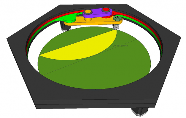
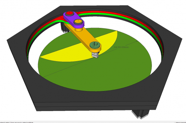
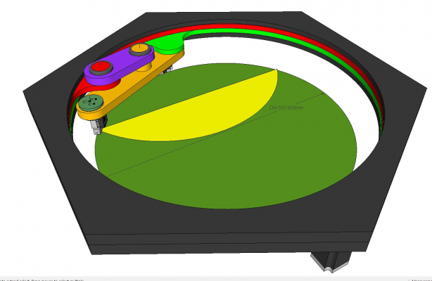
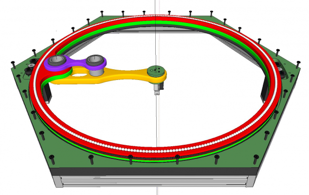
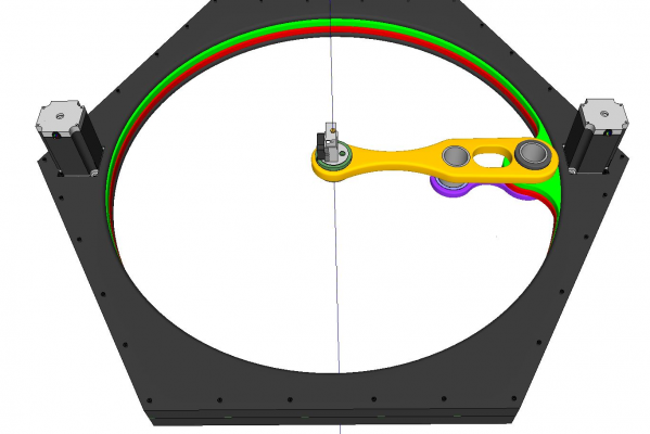
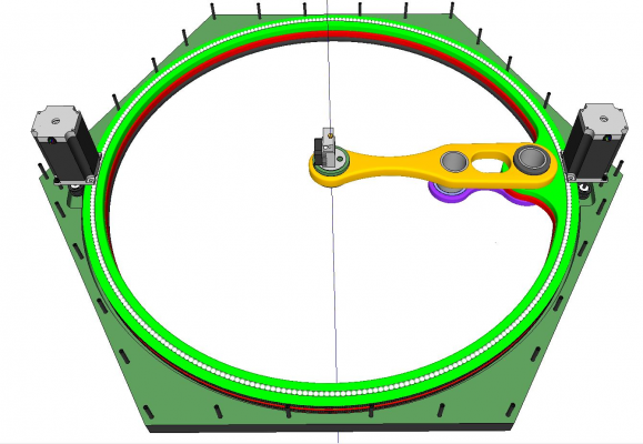
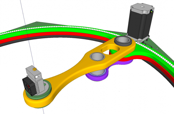
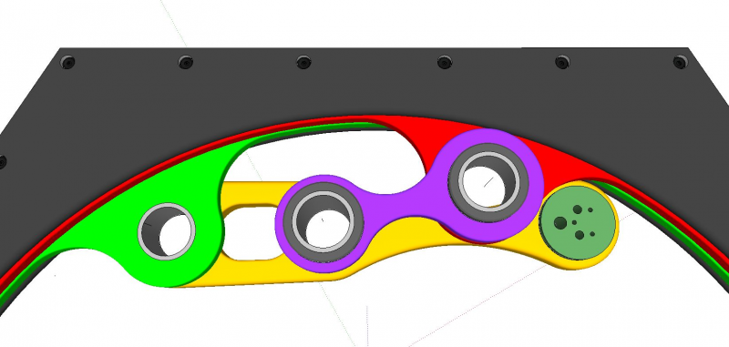
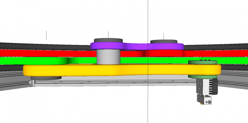
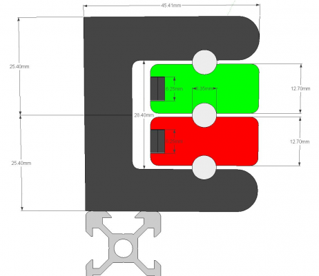
Here is a fixed motor design I call the Scara Hex. The arm motion is a derivative of a center pivot 360° Scara arm device like Yamaha produces, but the drive mechanisms here are moved to the perimeter ring. The red and green rings are driven separately using Nema 23 with overlapping belts for no slip, high torque movements. The rings float on Delrin balls were everything is captured within the top and bottom hex housings. The hot end floats on large centerless bearings so there is never any binding or twisting of the heater wiring or the filament. The center of the hot end passes through the center of the circle so there is a full 360° coverage of the approximately 600mm diameter print bed. The Z axis is handled conventionally on V-slot extrusions just as in a Delta design where each of the three legs are synchronously controlled either with cables, belts, or lead screws. The benefit of the design is the potential for a very large print volume given the large bed diameter and whatever Z height one chooses. The housing, rings, and arms are machined from MDF board then powder coated for airtight seal and hardness.
Edited 1 time(s). Last edit at 02/08/2016 02:04AM by simspeed.
Edited 1 time(s). Last edit at 02/08/2016 02:04AM by simspeed.
|
Re: Dreaming of a Static Motor Arrangement and Less Vitamins February 08, 2016 02:26AM |
Registered: 10 years ago Posts: 169 |
Here is a link to the Yamaha Orbit Scara robot I'm referring to. The movement of my design is contained within the outer loop of the Yamaha design where the perimeter ring pivot point replicates the outer pivot point (elbow) of the Yamaha center pivot arm. Yamaha Scara Robot
|
Re: Dreaming of a Static Motor Arrangement and Less Vitamins February 08, 2016 02:36PM |
Admin Registered: 13 years ago Posts: 730 |
Quote
WillStevens
It uses 14 relays for the stepper motor driver, 15 for the 2-bit divider stage and 2 for the clock. The clock timing is determined by two capacitors made from sodium-bicarbonate solution and aluminium foil (in the glass beakers).
I like the capacitors.

Do you have an estimate for what value they are? What is the maximum clock speed? Are the capacitors necessary or does it just run at full speed when they are removed? Can you share a circuit diagram for this version too?
|
Re: Dreaming of a Static Motor Arrangement and Less Vitamins February 09, 2016 06:37PM |
Registered: 12 years ago Posts: 17 |
Here's the relay clock circuit:
http://www.srm.org.uk/transfer/relay_clock.jpg
It doesn't produce an entirely clean output - there is bouncing for a few milliseconds on the transitions, more so on the closed-to-open transition than on the open-to-closed transition. That doesn't seem to matter. However, if I take the clock signal from the normally open contact of the relay on the right (rather than from the NC contact of the relay on the left as in the diagram) the bouncing does seem to matter and the clock is not able to properly drive the rest of the circuit - I'd like to understand why.
If the capacitors are removed the clock oscillates very irregularly with a frequency of about 300Hz, so the capacitors are necessary.
The sodium-bicarbonate "capacitors" give the same clock frequency (about 15 Hz) as 40 microfarad capacitors. I briefly tried to characterize them this evening, but without success - I thought perhaps they might behave like a resistor and capacitor in parallel, with another resistor in series, but it seems to be more complex than that.
The circuit seems to run okay without missing steps at 26Hz, but at 30Hz it begins to miss steps every so often - the part of the circuit that seems to fail is the divide-by-N stage. It's possible that a cleaner clock signal would give a higher maximum operating frequency.
I'll draw a diagram for the rest of the circuit at the weekend - since making it I've thought of some improvements that might reduce the relay count and increase the maximum operating frequency, but I haven't tried them out yet.
|
Re: Dreaming of a Static Motor Arrangement and Less Vitamins February 14, 2016 06:38PM |
Registered: 12 years ago Posts: 17 |
Here is the circuit diagram for the divider part of the video of the stepper motor speed controller from my earlier post.
http://www.srm.org.uk/transfer/stepper_speed_control2.jpg
The other parts of the circuit are the clock and the stepper driver from previous posts (Clock, Stepper Driver).
The simplification that I had hoped to make (mentioned in my last post) did not work - not yet at least.
I've also been working on a punched card reader and 3D printed relay:
Punched card reader
Relay
Edited 1 time(s). Last edit at 02/14/2016 06:39PM by WillStevens.
|
Re: Dreaming of a Static Motor Arrangement and Less Vitamins March 10, 2016 01:34AM |
Registered: 13 years ago Posts: 26 |
While it's not a completely static motor design, the Snappy RepRap printer has gotten rid of most of the standard vitamins, to the point that it snaps together without screws, and uses no pulleys, belts or metal rails, and the frame is completely printed.
|
Re: Dreaming of a Static Motor Arrangement and Less Vitamins March 13, 2016 03:04PM |
Registered: 12 years ago Posts: 17 |
@Revarbat: I've been following your work on Snappy RepRap since I came across it last year - it's really impressive and I hope to make one when I find the time.
I've started a blog about exploring the possibility of making a Reprappable control system for a Reprap:
RelayRepRap blog
I've started a blog about exploring the possibility of making a Reprappable control system for a Reprap:
RelayRepRap blog
|
Re: Dreaming of a Static Motor Arrangement and Less Vitamins May 01, 2016 12:44PM |
Admin Registered: 13 years ago Posts: 730 |
Hi Will (and everyone else). I saw the latest post on your blog with the Overall plan for a 2D plotter. I can't wait to see this in action! 
In related news, there was a recent post on Hackaday that readers of this thread might be interested in:
Cardboard and paperclip CNC plotter destined for self-replication
The cardboard and paperclip CNC is driven by an arduino and RC servos, but it is not hard to imagine driving that machine with a relay-reprap controller.
|
Re: Dreaming of a Static Motor Arrangement and Less Vitamins May 02, 2016 06:06PM |
Registered: 12 years ago Posts: 17 |
Hi Matt,
The cardboard CNC is interesting - I like the hand-driven part of the video from about 4min 30s.
I got a gravity powered unidirectional stepper motor working this morning:
Gravity powered stepper motor
It needs more work to increase the available torque - the diameter of the toothed wheel could be increased.
I expect that the solenoid/electromagnet actuator can also be improved. It consumes about 7W when switched on.
I recently came across a mechanical Turing machine that uses gravity driven unidirectional motors (with a differential to get bidirectional motion).
Artificial muscle computer
|
Re: Dreaming of a Static Motor Arrangement and Less Vitamins May 03, 2016 03:58PM |
Admin Registered: 13 years ago Posts: 730 |
Quote
WillStevens
It needs more work to increase the available torque - the diameter of the toothed wheel could be increased.
I expect that the solenoid/electromagnet actuator can also be improved. It consumes about 7W when switched on.
I can't really see the details of the mechanism in the video, so it may already incorporate what I am about to suggest, but here goes anyway:
Would it help to use an escapement mechanism like that used in clocks? This might allow better amplification (i.e. a larger torque could be controlled with a smaller solenoid force).
There are several designs floating around:
Parametric Graham Escapement
Simple Graham Escapement
Alternate designs that might also work include the Verge Escapement, Single-pin Escapement, and Pin-wheel escapement.
|
Re: Dreaming of a Static Motor Arrangement and Less Vitamins May 07, 2016 02:57PM |
Registered: 9 years ago Posts: 96 |
This obsession with a self replicating plastic machine just blows my mind given the stated goal of it. They already have self replicating machines. Its called a lathe, and they have been here a while.
I honeslty commend you all on your genius and your effort, but do you really think that you are going to design a relay driven 3d printer, then send the 300 relays needed to drive it (or maybe just the nails and coils of wire for diy relays) with a bag of 3D printed parts to an uneducated impoverished man in the third world who will somehow know how to read your instructions (hey... No computers, better 3D print them too) and assemble and debug a huge series of logic gates?
This obsession is more than anything, a waste of resources. I want us to innovate, try new things, etc, but I dont want us to sit around having these sci fi... Or should i say retro sci fi fantasies that we are going to save the works or improve the lives of the destitute by some silly only plastic machine. Other materials exist for a reason.
|
Re: Dreaming of a Static Motor Arrangement and Less Vitamins May 07, 2016 04:44PM |
Registered: 12 years ago Posts: 1,236 |
Well, I have acquired about 2000 relays for free, so I am looking for something to do with them 
On the subject of retro sci-fi, I recent read Valis by Philip K Dick, and while previously I was an atheist, I am now becoming convinced by "Horselover Fat" that the Universe was indeed created by a deity, but an insane one. That actually explains the nature of the Universe much better. I also understand better the wisdom of Douglas Adams:
Although the next lines are :
Edited 1 time(s). Last edit at 05/07/2016 04:45PM by bobc.
What is Open Source?
What is Open Source Hardware?
Open Source in a nutshell: the Four Freedoms
CC BY-NC is not an Open Source license

On the subject of retro sci-fi, I recent read Valis by Philip K Dick, and while previously I was an atheist, I am now becoming convinced by "Horselover Fat" that the Universe was indeed created by a deity, but an insane one. That actually explains the nature of the Universe much better. I also understand better the wisdom of Douglas Adams:
Quote
Douglas Adams
Slartibartfast: “Perhaps I'm old and tired, but I think that the chances of finding out what's actually going on are so absurdly remote that the only thing to do is to say, "Hang the sense of it," and keep yourself busy. I'd much rather be happy than right any day.”
Although the next lines are :
Quote
Arthur Dent: "And are you [happy]?
Slartibartfast:"Ah, no. Well, that's where it all falls down, of course.
Edited 1 time(s). Last edit at 05/07/2016 04:45PM by bobc.
What is Open Source?
What is Open Source Hardware?
Open Source in a nutshell: the Four Freedoms
CC BY-NC is not an Open Source license
Sorry, only registered users may post in this forum.
