Home
>
Developers
>
Topic
DIY budget heated bed
Posted by TheJones
|
DIY budget heated bed December 23, 2013 04:54AM |
Registered: 10 years ago Posts: 79 |
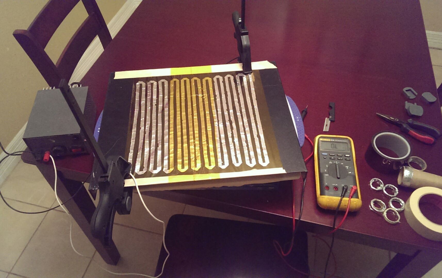
I'm building a machine with a 12"x12" bed, and had a stoppage in my progress, so I decided to mess around and see if I could make a heater for cheap, out of stuff I already had. I may be reinventing the wheel here, but I didn't see a thread about it when I did a search, do I figured I would post the evenings progress here.
My thought was to use a ribbon of aluminum foil, sandwiched between two layers out kapton tape. I figured that the tape will hold up to the temps, and as long as I can get the resistance right, the aluminum should work.
What you see in the picture is my fist attempt/test. The coil ended up being 1.3 ohms, which is a bit light. I haven't done the math on it yet, but I'm guessing that I'll need about 1.5x as many passes in my final unit.
I was so excited to test my idea, that I didn't think about its amp draw vs. the power supply. It heated up quickly, getting to the point where it was uncomfortable to hold my hand on the underside of the plate in less than two minutes, before it popped the fuse on the power supply. (lol oops)
I'm going to do some more figures and tests on it tomorrow, after I get some sleep and dig out a beefier power source.
I plan on squishing this thing between a plywood bed and a glass build surface. Do any of you guys with more experience see a problem with any of this? Is a reason that I should drop this idea, or do you think it's worth pursuing?
|
Re: DIY budget heated bed December 23, 2013 05:40AM |
Registered: 11 years ago Posts: 313 |
|
Re: DIY budget heated bed December 23, 2013 01:39PM |
Registered: 10 years ago Posts: 79 |
Nichrome would probable work well, but I had a roll of aluminum foil in the kitchen 
I just wanted to see if i could make a decent, reliable heater for cheap, and it seems to be working out so far.
I hooked a PC power supply to it, and right now it's chugging along, and hot enough that I can only hold my hand on it for a few seconds.
I'm going to go get a digital thermometer later, and see what it's actually running at. Then I'm going to make my final design with the needed amount of turns in the coil to get 2 ohms, and see how it holds up when I finish my printer. Only time will tell on that one.
Once I get my final unit made, I can do a more detailed write up on the built, if anyone is interested.
|
Re: DIY budget heated bed December 23, 2013 02:37PM |
Registered: 10 years ago Posts: 1,381 |
@TheJones ,
Cool project!
I'm collecting ideas for a Dia. 400 mm to 600 mm, (16.00" to 24.00") heater.
I bet inexpensive Kanthal resistance wire would work well with your homemade Kapton hot plate.
Idea:
If the heated Kapton tape adheres well to glass, tape Kanthal resistance wire directly to the glass substrate.
It would probably be best to coat the wire with CPU thermal compound to mitigate air gaps, (i.e. make it more efficient).
Kanthal 32 AWG Gauge A1 Wire
$4.69, 100' Roll
Heat resistant up to 1500 degrees Celsius
Resistance = 13.75 Ohms/ft at room temp
008 in. .20 mm
Shape: Round
FYI: this is what is used in ePens, eCigarettes, vaporizers.
High-Temp Hot End
[forums.reprap.org]
|
Re: DIY budget heated bed December 26, 2013 10:06AM |
Registered: 11 years ago Posts: 364 |
|
Re: DIY budget heated bed December 26, 2013 10:38AM |
Registered: 10 years ago Posts: 1,381 |
|
Re: DIY budget heated bed December 29, 2013 07:54AM |
Registered: 11 years ago Posts: 364 |
|
Re: DIY budget heated bed June 18, 2014 09:44AM |
Registered: 9 years ago Posts: 6 |
|
Re: DIY budget heated bed June 22, 2014 04:10AM |
Registered: 11 years ago Posts: 251 |
I really like this idea for the heating element.
I would not recommend a plywood bed. I used to have one, it seemingly randomly adjusts itself enough to need constant re-levels (moisture differential most likely)
Personally I would recommend a dibond sheet as the main stiff component of the bed. Then sandwich two thick pieces of flat corrugated cardboard between the element and the dibond. This is the arrangement I now have, the cardboard is an excellent insulator, the dibond only gets slightly warm to touch. The dibond sheet was £3 for a slightly bigger than 12x12" sheet. It's very easy to cut and drill, and is really light and stiff. The offcuts were also quite useful for bodge jobs :p
|
Re: DIY budget heated bed August 17, 2014 11:29AM |
Registered: 11 years ago Posts: 381 |
Dibond is a great material that is often under utilized. I've used cardboard insulators in the passed but, I've found that cork works best. You can typically find it anywhere. My first test run using cork, it was taken off of a cork board that I found at a thrift store for a buck.
--------------| For Everything |--------------------------
Check it out here:
[reprapsquad.wordpress.com].
---------| For Everything Prototype Related |------
Now featuring comp case mods:
[RepRapLab.wordpress.com]
--------------| Find us at Twitter|------------------------
@REPRAPSQUAD (RS Main)
[mobile.twitter.com]
@REPRAPSQUADHQ (ProtoLab)
[mobile.twitter.com]
|
Re: DIY budget heated bed August 18, 2014 09:25AM |
Registered: 10 years ago Posts: 14,672 |
How about a sheet of aluminium foil glued to a sheet of hardboard? Then cut thin strips out of the foil so that the remaining foil zigzags between the two sides. Then use photo frame clips to clamp a 4mm glass plate on top to serve as the printing bed. The glass will provide the stiffness, the hardboard needs to be flexible enough to conform to the glass. To mount it, you could epoxy three threaded pillars to the underside of the hardboard, or make the hardboard slightly larger than the glass and drill some mounting holes in it just outside the glass.
You could possibly measure the bed temperature by monitoring the resistance of the foil itself and calibrating it at room temperature, or you could leave a small hole in the middle of the foil/hardboard for a thermistor.
Large delta printer [miscsolutions.wordpress.com], E3D tool changer, Robotdigg SCARA printer, Crane Quad and Ormerod
Disclosure: I design Duet electronics and work on RepRapFirmware, [duet3d.com].
|
Re: DIY budget heated bed August 19, 2014 07:20AM |
Registered: 10 years ago Posts: 78 |
My approach is very simple, cheap, easy to do and tested: RepReap-Wiki:Robert's heated bed.
I'm working with an 18A-variant of this bed (that's 216Watt at 12V; 200mm x 200mm) at 130°C.
Due to other projects I didn't find the time to test this bed without Kapton, just polished aluminum and e.g. hairspray. Maybe this would work too at high bed-temps.
Key to this cheap solution is Traumflug's SevenSwitch, that can easily drive the bed, even without extra heatsink of the MOSFET (I'm cooling it together with the rest of my electronic with the fan of the power-supply).
Possible variants/improvements:
Use thicker aluminum-sheets for a really plain surface (while most 3mm sheets will do, but some aren't really flat) -> raises costs of course
Some sorts of isolated copper-wire may need extra isolation to the aluminum, because the wire-isolation may fail above 100°C (should be noticed in the specifications of the wire). Use Kapton on the heated side for this purpose then, because it electrically isolated, while being thin enough not to block the heat from the wire.
Just my 2 (Euro-) cents.
|
Re: DIY budget heated bed August 26, 2014 03:01PM |
Registered: 10 years ago Posts: 78 |
|
Re: DIY budget heated bed August 29, 2014 12:54PM |
Registered: 10 years ago Posts: 78 |
By the way: What is the maximum current I can drive with SevenSwitch at 12V?
I'd like to make a test with 30A, but don't want to burn my board. I want to try what happens using a heater with only 0.4 Ohms electrical resistance.
The Wiki-entry says, SevenSwitch is good for only 15A. I'm using it at 18A for several weeks now with now problems. The wires get warm (app. 45°C), but they are only 1.5mm in diameter (good for 16A though) and far away from critical temperatures.
The MOSFET should be no problem (can switch up to 150A at 10V) and I can strengthen the copper traces of the SevenSwitch-board, use doubled wires for supply and heater and solder them to the board (I guess the terminals won't survive 30A). But I don't know if I need to change the capacitor or other parts in the circuitry in order to get 30A-support.
The power-supply gives 56A at 12V. This at least should be enough for my experiment.
P.S.: What I want to do: I want to see what a 220mm x 220mm x 3mm sheet of aluminum with an electrical resistance of 0.4 Ohms does, if directly connected to 12V at 30A. If it does what I'd like to see, you can forget the heating wires and any Kapton on "my" heated bed. You'd just need to attach fat wires to the sides of heated bed, connect them to a slightly improved SevenSwitch-board and use a really powerful power unit.
Edited 2 time(s). Last edit at 08/29/2014 03:10PM by RobertKuhlmann.
|
Re: DIY budget heated bed August 29, 2014 01:28PM |
Registered: 10 years ago Posts: 14,672 |
There is no way that the mosfet will switch 150A, despite its theoretical 150A rating. Assuming it is driven by a 5V signal (i.e. from 5V RepRap electronics, not the new 3.3V Duet electronics), then the maximum that you should ask the the mosfet to pass is 32A (the value at which Rds(on) is specified for Vgs=4.5V). At that current, it will dissipate about 4W and need a modest heatsink. In fact, you should put a heatsink on the mosfet if you want to pass more than 16A through it.
Bear in mind that to get uniform current flow (and hence uniform heating) through a sheet of alu, you will need to bolt strips of copper sheet or much thicker aluminium plate to two opposite edges, and feed the current to the plate via those.
Where do you get the figure of 0.3 ohms from? I make the resistance between opposite edges of that sheet about 10 microohms.
Edited 1 time(s). Last edit at 08/29/2014 01:28PM by dc42.
Large delta printer [miscsolutions.wordpress.com], E3D tool changer, Robotdigg SCARA printer, Crane Quad and Ormerod
Disclosure: I design Duet electronics and work on RepRapFirmware, [duet3d.com].
|
Re: DIY budget heated bed August 29, 2014 03:09PM |
Registered: 10 years ago Posts: 78 |
You're right. I forgot to mention the cooling of the MOSFET, which I will do too, of course. I didn't need a heat-sink until now (driving 18A though), because the MOSFET is in the direct air-stream of the fan of my power-supply. But adding a heat-sink will be no problem.Quote
dc42
There is no way that the mosfet will switch 150A, despite its theoretical 150A rating. Assuming it is driven by a 5V signal (i.e. from 5V RepRap electronics, not the new 3.3V Duet electronics), then the maximum that you should ask the the mosfet to pass is 32A (the value at which Rds(on) is specified for Vgs=4.5V). At that current, it will dissipate about 4W and need a modest heat-sink. In fact, you should put a heatsink on the mosfet if you want to pass more than 16A through it.
The Signal is RAMPS 1.4 5V Servo-out. Reads like 30A is within the specifications of the MOSFET. Good news so far.
I think I don't need a uniform current flow, because the aluminum is a good heat conductor. This is my experience from my current heated bed, where the positions of the heating-wire-loops are not that important. Even if there would remain some minor temp-differences, these are not very important, as long as the lowest temp (which should be basis of the thermistor-measurement) is high enough. I couldn't see any differences in adhesion of prints to the bed between 130°C and 110°C for ABS (plain aluminum with hairspray).Quote
dc42
Bear in mind that to get uniform current flow (and hence uniform heating) through a sheet of aluminum, you will need to bolt strips of copper sheet or much thicker aluminum plate to two opposite edges, and feed the current to the plate via those.
I'll give it a try and maybe will possess the most simple, most efficient, least resource consuming, fastest and cheapest heated bed possible.
Or worst case: I'll need to build a new SevenSwitch-board and change the burned cables.

Edited 1 time(s). Last edit at 08/29/2014 04:50PM by RobertKuhlmann.
|
Re: DIY budget heated bed August 29, 2014 03:13PM |
Registered: 10 years ago Posts: 78 |
|
Re: DIY budget heated bed August 29, 2014 04:08PM |
Registered: 10 years ago Posts: 78 |
Maybe I wasn't exact enough: The "sheet" is 220mm x 220mm x 3mm.Quote
dc42
... Where do you get the figure of 0.3 ohms from? I make the resistance between opposite edges of that sheet about 10 microohms.
I don't know the alloy at the moment...
Edited 1 time(s). Last edit at 08/29/2014 04:11PM by RobertKuhlmann.
|
Re: DIY budget heated bed August 29, 2014 05:55PM |
Registered: 10 years ago Posts: 14,672 |
Yes, I calculated the resistance of that size sheet. The resistivity of aluminium (rho) is 2.8e-8 ohm-metres at 20C. So the resistance of your sheet, from one edge to the other, is:
R = rho * L / A = 2.8e-8 * 220e-3/(220e-3 * 3 e -3) = 2.8/3 * 1e-5.
It may vary from this a little if it is an alloy. This resistance is much to low for the aluminium sheet to be usable as the heating element.
Large delta printer [miscsolutions.wordpress.com], E3D tool changer, Robotdigg SCARA printer, Crane Quad and Ormerod
Disclosure: I design Duet electronics and work on RepRapFirmware, [duet3d.com].
|
Re: DIY budget heated bed August 30, 2014 03:44AM |
Registered: 13 years ago Posts: 7,616 |
0.4 ohms straight through the aluminium? Never ever. For fun I did the theoretical calculation, the actual resistance should be about 9.1 microohms.
You can do such tricks with carbon fibres embedded into something non-conducting, like Polyester or Epoxy resin.
You can do such tricks with carbon fibres embedded into something non-conducting, like Polyester or Epoxy resin.
| Generation 7 Electronics | Teacup Firmware | RepRap DIY |
|
Re: DIY budget heated bed August 30, 2014 05:10AM |
Registered: 10 years ago Posts: 78 |
|
Re: DIY budget heated bed May 19, 2015 01:39PM |
Registered: 10 years ago Posts: 79 |
So, it's been a while, but I have picked this project back up.
I now have an IR digital thermometer, so I can take actual readings (instead of my old test method, which consisted of "Ouch, that's hot!")
I attached a picture with some data on it, so when I talk about the different versions, you can see what I mean.
For testing purposes, I have made 3 versions so far.
v.1 was the one pictured in the first post of this thread. I made it about a year ago, and it was sort of a stab in the dark. It ended being 1.4 ohm, and got pretty hot (before I had a thermometer).
I read on the reprap wiki that these heaters should be 2ohms, so I did the math based off what I have learned with v.1 and then made the v.2 heater. When finished, it was 30 winds, and 3mm width, and it measured out at 2.1ohms. Expecting success (always a mistake), I hooked it up to a power supply, and was slightly confused to find that it was only going up to about 65c. I did some more reading and thinking, and came to the conclusion that maybe 2ohms was too high.
At this point, I went back to v.1 and did another test, this time scooting my connection over until the coil's resistance was down to 1ohm (I called this configuration v.1.5). SUCCESS! It heated up to 130C very quickly, and stayed there.
So, on to v.3. I used the same number of winds as v.1.5, but made them thicker (9mm) in hopes of more evenly distributing the heat. Surprise #1 was that it measured at .7ohms, significantly lower than I thought it would. I assumed that this was because of the wider strips, and pressed forward. Surprise #2 was quite vexing: it would not go above 70c.
I'm not sure why v.3 performed so poorly, but but I assume that it has something to do with the incressed width of the strips. I am planning to make a v.4 with 15 winds at 3mm. However, I am worried that this will create thin bands of heat through the build surface. I think I am going to give it a try though, it can't be any worse than NiChrome wire in that respect, right?
|
Re: DIY budget heated bed May 19, 2015 02:31PM |
Registered: 8 years ago Posts: 5,232 |
|
Re: DIY budget heated bed May 19, 2015 02:56PM |
Registered: 10 years ago Posts: 79 |
For connection to the wires, I'm using non-conducive clamps to press the suffices together.
As far as current limiting power supplies, I'm not trying to control the temp, I'm having a problem getting them to go above 100c.
I'm out and about right now. Going to do more fooling around with it when I get home.
As far as current limiting power supplies, I'm not trying to control the temp, I'm having a problem getting them to go above 100c.
I'm out and about right now. Going to do more fooling around with it when I get home.
|
Re: DIY budget heated bed May 19, 2015 03:13PM |
Registered: 8 years ago Posts: 5,232 |
|
Re: DIY budget heated bed May 19, 2015 04:28PM |
Registered: 10 years ago Posts: 79 |
|
Re: DIY budget heated bed May 19, 2015 06:23PM |
Registered: 11 years ago Posts: 5,780 |
I did something similar to make a flexible ribbon to carry power to my heated bed. I cut strips of copper tape and sandwiched them between two layers of 5 mil thick Kapton tape. I have yet to test it on the printer, but it should handle the 22A my bed uses with only a couple degree temperature rise if my calculations are close to correct.
|
Re: DIY budget heated bed May 19, 2015 06:39PM |
Registered: 10 years ago Posts: 79 |
I made v.4 when I got home. It is a 3mm strip with 6mm spacing, 1ohm resistance.
At first, it was doing the same thing as the others, peaking at around 60-70C.
So I went back to v.1.5 and looked at it again. I realized that the part which was hitting the desired temperature was fully enclosed in tape.
At this point, I figured that maybe the aluminum was dissipating the heat too quickly for it reach the target temp, and the tape was insulating it slightly, letting the heat build. I then coated the v.4 coil in tape and its temp quickly shot up to +100C. Everything seemed great.
I then sandwiched the coil (at this point, it is essentially an aluminum based Kapton heater) between a piece of cardboard, and a sheet of glass.
The temp rose steadily to ~85C in the middle, but wouldn't go any higher. However, the only part of the coil not covered by glass hit temps of +100C. (not the contacts themselves, but the part of the trace that leads toward them.
I don't know whats going on with that. I know that reflective surfaces can throw off IR thermometers, but the cardboard on the underside of the plate is sitting at ~85c as well. Maybe it has something to do with the air gaps in there. Who knows.
This is aggravating.
I came up with this whole idea when I was looking at which type of heated bed I wanted, and I thought to myself "I wonder if anyone has ever tried that...?". I want to make this work, just because I'm a stubborn ass. But at this rate, I'm probably just going to buy a 300x300 silicon pad and be done with it.
|
Re: DIY budget heated bed May 19, 2015 06:59PM |
Registered: 11 years ago Posts: 5,780 |
|
Re: DIY budget heated bed May 19, 2015 10:05PM |
Registered: 10 years ago Posts: 79 |
I don't know what is so magical about v.1, but it's working.
I peeled up the extra aluminum that I didn't need, and got the total resistance to 1ohm, then I encased the rest of the uncovered area in kapton tape.
I sandwiched it between the glass and the aluminum spring loaded bed. It's running stable at 100c. Because of the parts I removed to get the resistance lower, the heating element is only 200x300, while the total bed is 300x300, so I've lost a bit of print area. But it will be enough to get printing.
That's good enough for me. I'm going to run it for a while and maybe upgrade to a silicon pad later, once I've used this one long enough to claim victory.
Edited 1 time(s). Last edit at 05/19/2015 10:09PM by TheJones.
Sorry, only registered users may post in this forum.