Home
>
Developers
>
Topic
Wire all negatives in one?
Posted by MrDoctorDIV
|
Wire all negatives in one? April 24, 2014 02:17PM |
Registered: 10 years ago Posts: 790 |
As I understand it, you can have multiple positives and a single negative to run different things on the same circuit, even with different currents and voltages.
Can this be done with circuitry? Could I, for example, wire all of the end stop negatives to the same terminal, so long as the positives are in the respective terminals?
Can this be done with circuitry? Could I, for example, wire all of the end stop negatives to the same terminal, so long as the positives are in the respective terminals?
|
Re: Wire all negatives in one? April 25, 2014 12:13PM |
Registered: 11 years ago Posts: 251 |
It's better to think of the negative terminal as "ground", in other words it's at 0v. You could have negative voltages in some circumstances, in which case you you wouldn't want to arbitrarily connect things together!
However with reprap electronics I don't see why not. Personally I would use a volt meter to do a continuity check between the negative points I want to bundle together. If they are directly connected to each other (as they will be in most normal circuit designs) then it should be fine providing you aren't pushing too much current through somewhere.
Edited 1 time(s). Last edit at 04/25/2014 12:20PM by konwiddak.
|
Re: Wire all negatives in one? April 25, 2014 01:35PM |
Registered: 10 years ago Posts: 790 |
|
Re: Wire all negatives in one? April 25, 2014 05:46PM |
Registered: 11 years ago Posts: 1,171 |
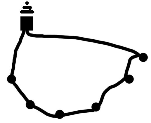
Most of my life I worked in the coin op industry, I worked on everything from arcade games, pinball machines and even slot machines. When grounding lights, buttons and such they always make a redundant loop, connect ground from one item to the next then return to ground at the end. This way a single ground can break any where and everything till functions fine. I have attached a very crude drawing to show the method.
|
Re: Wire all negatives in one? April 26, 2014 03:27AM |
Registered: 11 years ago Posts: 198 |
Normally, when grounding temprature sensors and other noise sensitive stuff, it's best to have individual ground wires, running all the way to the PCB.
But... the only thing that I can come up with in a RepRap that is somewhat noise sensitive, is the thermistors, and they are filtered both analog and digitally. And add to this that the external ground in a Reprap really doesn't carry any current, you'll probably be good, if you just dont source the common ground directly from the PSU.
Still.. Having messed with power amplifiers, and engine control electronics for cars, I would use the extra two ground wires for the thermistors.. the rest can just be a common ground.
But... the only thing that I can come up with in a RepRap that is somewhat noise sensitive, is the thermistors, and they are filtered both analog and digitally. And add to this that the external ground in a Reprap really doesn't carry any current, you'll probably be good, if you just dont source the common ground directly from the PSU.
Still.. Having messed with power amplifiers, and engine control electronics for cars, I would use the extra two ground wires for the thermistors..
the rest can just be a common ground.
|
Re: Wire all negatives in one? April 26, 2014 02:23PM |
Registered: 10 years ago Posts: 790 |
|
Re: Wire all negatives in one? April 26, 2014 05:50PM |
Registered: 10 years ago Posts: 115 |
|
Re: Wire all negatives in one? April 26, 2014 09:34PM |
Registered: 10 years ago Posts: 790 |
|
Re: Wire all negatives in one? April 27, 2014 02:47AM |
Registered: 11 years ago Posts: 198 |
|
Re: Wire all negatives in one? April 27, 2014 06:36AM |
Registered: 10 years ago Posts: 115 |
@Ralph very good point. To clarify further the negative of the heated bed/hotend is connected to the drain of the MOSFET. The source of the MOSFET then connects to ground. If you're using a board such as RAMPS etc then the MOSFET ground is already done on the PCB. Here's a diagram I found that should clarify:
Ignore the 1N4001 diode as this is usually for more inductive loads such as solenoids.
Edited 2 time(s). Last edit at 04/27/2014 06:40AM by samp20.

Ignore the 1N4001 diode as this is usually for more inductive loads such as solenoids.
Edited 2 time(s). Last edit at 04/27/2014 06:40AM by samp20.
Sorry, only registered users may post in this forum.