Home
>
Developers
>
Topic
Heat Compensated Bed Support First Test
Posted by the_digital_dentist
|
Heat Compensated Bed Support First Test February 08, 2016 11:00PM |
Registered: 11 years ago Posts: 5,780 |
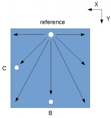
I have a 305 x 317 x 6.35 mm cast aluminum bed plate in my printer, supported by three screws that are used to level it. The three screws are anchored to a 6.35mm thick aluminum undercarriage which is in turn supported on three standoffs screwed to bearing blocks that ride on two fully-supported linear guide rails that are the Y axis of the machine. When the bed plate heats to ABS print temperature it expands about 0.7 mm. The diagram below shows how the bed expands as temperature rises. This puts lateral pressure on the leveling screws because they are firmly anchored to the unheated undercarriage below the bed plate but the holes in the bed plate are moving apart. The lateral pressure causes the plate to deform slightly, exhibiting the usual hump at the center of the bed.
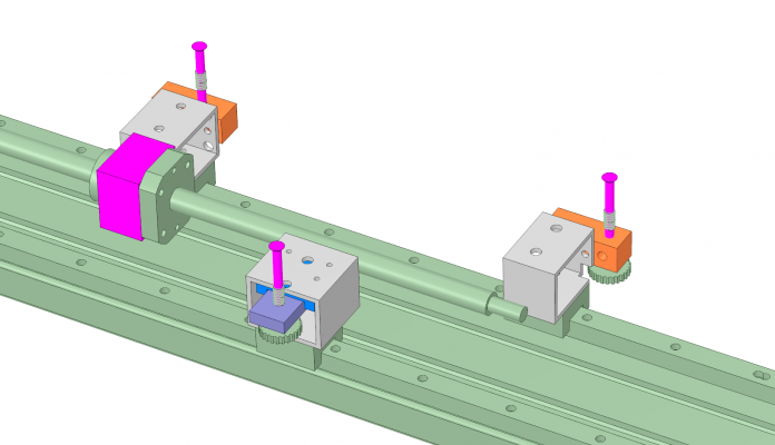
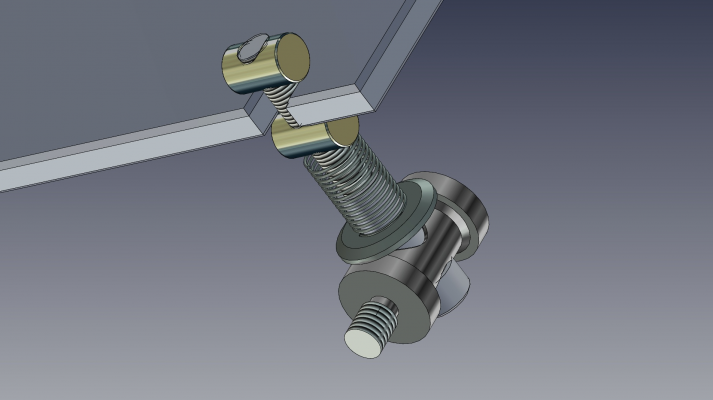
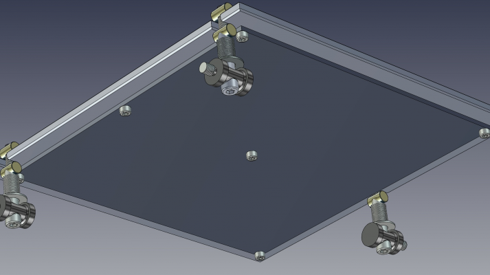
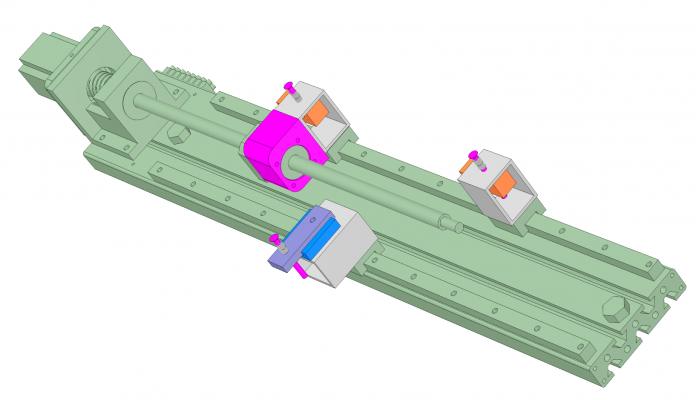
I thought about how to prevent this problem and keep the bed flat by eliminating the lateral pressure created by the temperature difference between the bed plate and the undercarriage. I decided the simplest way to fix it was to eliminate the undercarriage completely and let the three leveling screws and bearing blocks move independently. It is not an ideal situation from a mechanical engineering point of view, but I thought I'd try it anyway. If it worked I would shed about 500g of moving mass as well as reduce the hump in the bed when it heats up, a win-win situation. Here's what I came up with:
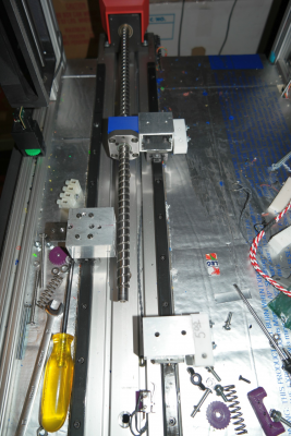
The bed plate, not shown, is supported by the three vertical screws with springs. Two of the screws are aligned along the Y axis of the machine (reference and B in the first diagram); the one at the left side is the reference screw that is set and never adjusted again. The other Y axis screw, on the right (B ), adjusts the pitch of the bed around the X axis. When the plate expands the two simply move apart along the Y axis, so by disconnecting the bearing block, standoff, and screw from the undercarriage plate, the block and screw at B are free to move away from the reference screw.
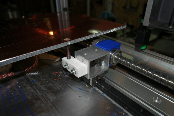
C is where the more interesting stuff happens. Notice that the expansion line between the reference and point C in the first diagram is not aligned with the Y axis. It has to move diagonally. It took a while to realize that since it was free to move along the Y axis, all I had to add was some freedom of motion in the X axis and it would then be free to move diagonally. I added a short linear guide that I bought via ebay for $9. The bearings and rails in these things are so precisely machined that there is no hand detectable play at all. They move only along the axis of the rail.
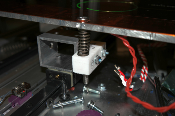
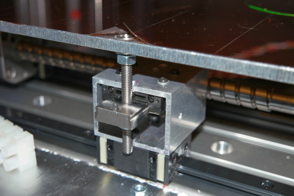
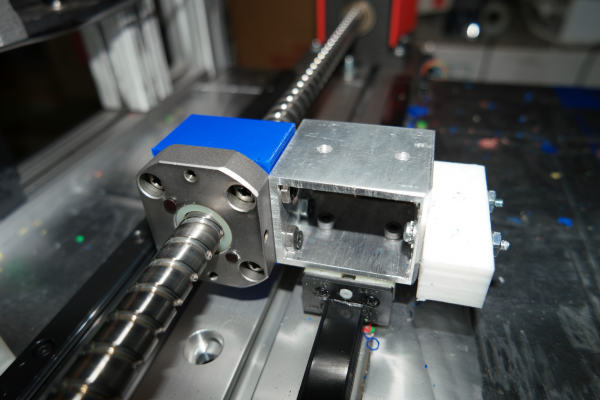
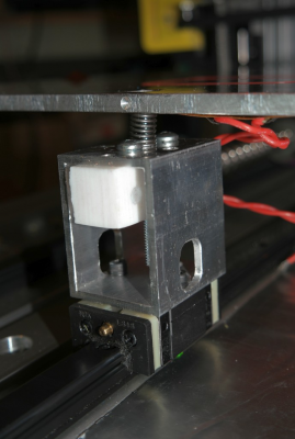
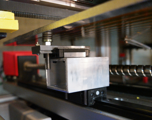
Today I tore apart the Y axis and set it up to use this new design. Here are some photos of the parts at B and C.
I didn't even attempt to print with it or measure the heated bed's flatness. As soon as I put it together I found flaws in the design that allowed too much extraneous movement. In the two pictures below you can see details of the reference point assembly. The movement was occurring where the teflon block was screwed to the side of the aluminum standoff (with a similar problem at the point B assembly. Just pushing and pulling on it caused it to rock.
I decided it wasn't worth testing until I could come up with a more stable design. Back to the drawing board!
Ultra MegaMax Dominator 3D printer: [drmrehorst.blogspot.com]
|
Re: Heat Compensated Bed Support First Test February 09, 2016 06:42AM |
Registered: 9 years ago Posts: 100 |
Interesting, the printer I am designing will use a similar size and configuration of bed to yours, so I will have to solve the same problem (I have a slight advantage though in that my bed moves in the Z axis, so shouldn't suffer lateral shaking). Where did you get the figure of 0.7 mm expansion, was that measured or calculated?
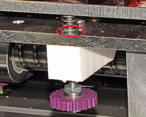
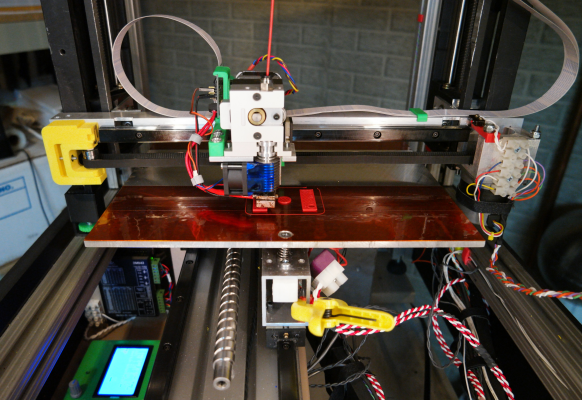
I was hoping to solve the problem by just using oversized mounting holes in the base plate (as circled on your printer below) for 2 of the mounting points, to allow some lateral movement.
If you only oversize your B and C point (so A acts as a rigid anchor point in the Y axis), don't screw the Teflon block to the baseplate, then with sufficient tension in your springs I think the posts could resist unwanted lateral movement as the bed moves, but still be able to move under expansion. It might take some trial and error with different sized Teflon blocks, as well as spring tension.
|
Re: Heat Compensated Bed Support First Test February 09, 2016 12:02PM |
Registered: 11 years ago Posts: 5,780 |
The motion I am primarily concerned with is along the Y axis as the bed is massive and jerks back and forth in that axis while printing. The support screws must be rigidly anchored or the bed will flop around in an uncontrolled way every time it reverses direction. In the original design, the teflon blocks are screwed to the undercarriage and the bed leveling screws are driven into undersized holes in the teflon so that they will be rigid also. My print surface quality tells me that this method works extremely well.
What I'm trying to do now is use the single reference point (the the leveling screw that attaches to the ball screw drive) as the only point that drives the rigid bed plate. I still need to support the other two points and they need to be able to level the bed, but they must be very stable except in the direction that the linear guides allow them to move. In those directions, the rigidity of the bed plate will restrain the motion and the thermal expansion of the plate will define that motion.
The expansion was calculated from the size of the plate, the material, the CTE, and the temperature rise.
In a machine that moves the bed only in the Z axis this problem is much easier to deal with. You anchor one point to the support system and the other two support points only support it from underneath- I would probably use magnets to help hold the plate down at those two points- two attached to the bed plate and two on the leveling screws, and let them slide against each other as the bed expands and contracts.
My printer has very rigid construction and I don't have to relevel the bed on a regular basis- usually only after I make some mechanical changes (such as the sort of work I'm doing now). I will probably eliminate the springs and simply bolt the plate down once I have the final undercarriage/support system worked out.
Ultra MegaMax Dominator 3D printer: [drmrehorst.blogspot.com]
|
Re: Heat Compensated Bed Support First Test February 10, 2016 09:05AM |
Registered: 8 years ago Posts: 260 |
> When the bed plate heats to ABS print temperature it expands about 0.7 mm
This is why I decided to eliminate the aluminum plate all together. And directly glue the mounting bolts
to a Borosilicate glass plate. This glass expands about 3 to 4 times less then aluminum. The heater will be sticked directly to the glass plate.
I didn't build this yet but all the parts are on the way. ( this will be my first 3D printer )
|
Re: Heat Compensated Bed Support First Test February 10, 2016 01:02PM |
Registered: 11 years ago Posts: 5,780 |
Understand that this is a minor problem I'm working on- the plate remains flat enough to print edge to edge at all temperatures (<+/-40 um). I am doing this work to see if my suspicion that the lateral force on the screws is what causes the bed to bow. The only other possibility I see is that the bed is always cooler near the edges and the temperature difference across the plate (warm at the center, cooler at the edges) may be the major cause of the bow. It may be that both factors are contributing.
The problem with glass is that it is a thermal insulator (and is breakable). If you glue the heater directly to it you can expect hot and cold spots. You may have problems with prints letting go in the cooler areas. We have a Taz printer at the makerspace that has a heater glued to a glass plate and we looked at it with a FLIR camera and found a 20C variation across the surface including a cool spot at the center of the bed about 75mm dia.
Ultra MegaMax Dominator 3D printer: [drmrehorst.blogspot.com]
|
Re: Heat Compensated Bed Support First Test February 10, 2016 01:23PM |
Registered: 9 years ago Posts: 100 |
|
Re: Heat Compensated Bed Support First Test February 10, 2016 01:37PM |
Registered: 11 years ago Posts: 5,780 |
I have done that.
Unheated bed flatness: [vimeo.com]
Heated bed flatness: [vimeo.com]
Ultra MegaMax Dominator 3D printer: [drmrehorst.blogspot.com]
Unheated bed flatness: [vimeo.com]
Heated bed flatness: [vimeo.com]
Ultra MegaMax Dominator 3D printer: [drmrehorst.blogspot.com]
|
Re: Heat Compensated Bed Support First Test February 10, 2016 01:51PM |
Registered: 9 years ago Posts: 100 |
|
Re: Heat Compensated Bed Support First Test February 10, 2016 01:54PM |
Registered: 11 years ago Posts: 5,780 |
|
Re: Heat Compensated Bed Support First Test February 10, 2016 02:14PM |
Registered: 9 years ago Posts: 100 |
|
Re: Heat Compensated Bed Support First Test February 10, 2016 02:48PM |
Registered: 11 years ago Posts: 5,780 |
The removal of the undercarriage plate and addition of the lateral linear guide at point C allows the thermal expansion to occur without putting any lateral stress on the plate because points B and C can freely follow the thermal expansion on their linear guides. The problem is that as I have built it, it allows too much extraneous motion of the plate which makes it useless for printing. It is a failed experiment not because it disproved the hypothesis but because it wasn't mechanically adequate to test it.
The test method is good, the implementation was poor. The plate rocks back and forth on the teflon blocks at the reference and point B because the blocks slide against the aluminum standoffs. The original design with the blocks screwed to the underside of the undercarriage plate prevented such extraneous motion. Once I have redesigned it and fabricated new parts that prevent the undesired motion, I will try again. If it behaves itself when moving the bed back and forth, I'll measure the flatness of the bed again at room temp and hot.
Here is an illustration of the problem that occurs at the reference. The same things happens at point B. I should have been smarter and anticipated it, but I'm getting old and my brain isn't quite what it once was... If the teflon blocks were screwed to the top of the standoffs this motion would not happen.
Edited 1 time(s). Last edit at 02/10/2016 02:48PM by the_digital_dentist.
Ultra MegaMax Dominator 3D printer: [drmrehorst.blogspot.com]
|
Re: Heat Compensated Bed Support First Test February 11, 2016 12:30AM |
Registered: 8 years ago Posts: 1,671 |
Timely Subject, best way to attach bed to bearings, something I'm also looking into,
Your first diagram appears to show the support plate is only half supported on rails that are close together,
if the rails where further apart and supported both edges, would that help, or would the expansion cause the same or more issues?
I notice your leveling delta is smaller than using full bed(though your beds bigger),
I suppose if using a larger triangle then the expansion might be harder to compensate for, or maybe just tight things up.
In my first setup I realized I would have to find a way to reduce tilt in Y axis, as direction changed, it was exaggerated in my setup, because I have only a small narrow 25mm bar holding the bed, plus I had one 6mm perspex support attached to a 3mm perspex(while waiting for the heatbed) Plus on top of all that I had an unsecured piece of heavy glass(just for pictures)....the glass was introducing most of the movement/dipping I could see and judder you could feel, so obviously reducing speed & jerks helped a little, but as I will replace soon with cast plate it didn't concern me too much.
Now I have the 3mm heatbed things are much stiffer, I hope when I remove the perspex bed support and replace with cast plate, things will get even stiffer, but still micron movement could still be in there. I will have to decide, do I move from 2 bearings to 3, or 4 One for each corner of cast plate, that should reduce tipping to nothing. I have 500mm rails so have enough space, but if I can get away with 2 great. Ideally the new setup would not have the heatbed supported on springs, as it should be under the cast plate in direct contact(till I find out it's not good enough)
With Mk3 bed under the wider cast plate( about 240mm square), though wonder on the ability of the Mk3 to heat the plate, and it's expansion could cause similar issues, may change to silicone later but then maybe more plate needed to sandwich silicone heater,
but only want pla temps at first so should be fine.
I wanted blind holes in the tooling plate for adjusters to screw into, and adjust from below, but through holes make things easier, you have the through holes on the blocks underneath, I also have that option but with these spigots i'm trying to incorporate, and if I use those cylindrical furniture nut things, the adjustment screw need not be totally vertical.
Waffle Waffle toasty waffle, easier with a picture to show where i'm upto
Might need another washer or alternate arrangement, suggestions welcome.
If bed is only attached in center(with the leveler i spotted) the expansion wouldn't matter too much, though my bearing arrangement allows them to rotate a little along axis, width expansion might not matter too much, adding more bearings, hopefully they would just move apart, but as you have discovered one attachment point might need to slide or be allowed to rotate a little.
If bed is supported at each corner, it makes it more tricky to add the 3 point leveling without another layer of aluminium, but just using 3 point means the corners of the bed are no longer supported.
I'm hoping to make(piece together) a special stud improve on above, that does away with the spigot, which has to be 1/4" one end, maybe a bit of smooth shaft, but also 6mm thread somewhere for adjustment, other end into the cast plate(none through hole) but stud may need to be telescopic with Knurled Disc Nut but they are a little large, not cheap either.
If somethings on a spring surely there always be some play in the system.
I also wonder how much heat gets carried away through all metal bed link, or melting plastic blocks.
Edited 1 time(s). Last edit at 02/11/2016 12:32AM by MechaBits.
|
Re: Heat Compensated Bed Support First Test February 11, 2016 02:03AM |
Registered: 11 years ago Posts: 5,780 |
I placed the reference and the point B along the center line of the bed for three reasons. First, the Y axis base plate was only wide enough to space the linear guides about 1/2 the width of the bed. Second, putting one linear guide under the center line of the bed and driving the bed along that guide with the ball screw, no twisting torque would be created when reversing the direction of the bed motion (there's equal bed plate mass on either side of the center line). Third, if the screws were farther apart, the undercarriage would have to be larger and more massive. Spacing them wider wouldn't have created any more problems with thermal expansion. The compensation method I am trying to test would work anyway, without any changes.
I don't know how you're going to anchor those leveling screws, but they need to be rigidly held parallel to the Z axis. If they can tilt or there is any slop in the fit of the screws and their nuts at all, the bed is going to flop around every time it reverses direction. Screws don't normally fit tightly in nuts. You can wiggle them easily. That's why I used the teflon blocks- the screws fit tightly and there's no play (as long as I do a decent job of anchoring the teflon blocks, which I failed to do in this test).
Whatever you do, don't use four supports. It will make leveling the bed without bending it and/or the undercarriage nearly impossible. I know you see that sort of arrangement on a lot of machines, but it is dead wrong.
Ultra MegaMax Dominator 3D printer: [drmrehorst.blogspot.com]
|
Re: Heat Compensated Bed Support First Test February 11, 2016 06:00AM |
Registered: 8 years ago Posts: 260 |
|
Re: Heat Compensated Bed Support First Test February 27, 2016 08:10PM |
Registered: 11 years ago Posts: 5,780 |
Round two: I redesigned the supports so that the teflon blocks now screw to the top surface of aluminum stand-offs. By assembling it this way the height of the bed is only slightly changed from when I used the undercarriage, so I don't lose any print height. I will have to move the entire Y axis over about 2 cm because the center line of the bed plate has shifted, but that's just loosening two bolts, sliding it over and retightening (and cutting new foam pieces to insulate the bottom of the machine).
I haven't finished the roll screw assembly yet- hopefully later this evening- but I tried moving the bed with it mounted on just the two pitch screws and it seems to work fine. The pitch adjust screw (first picture) is now free to follow expansion of the bed without creating lateral force on the bed plate. When I get the roll screw assembly mounted and can test again we'll see if the bed remains flat at high temperature.
Edited 2 time(s). Last edit at 02/28/2016 02:02PM by the_digital_dentist.
Ultra MegaMax Dominator 3D printer: [drmrehorst.blogspot.com]
|
Re: Heat Compensated Bed Support First Test February 27, 2016 08:25PM |
Registered: 9 years ago Posts: 1,873 |
The idea of doing away with the carriage once you have a sufficiently stiff bed is brilliant, but, if I understand correctly, all of the bed acceleration now has to be transmitted from the motor to the bed via a single mounting screw - the reference screw in your original description. Have you had to beef up that mounting point to cope with the load?
|
Re: Heat Compensated Bed Support First Test February 27, 2016 09:52PM |
Registered: 8 years ago Posts: 1,671 |
the 2 attachment points on the center line, I know the idea is for them to be able to move apart, they are tied with the bed, I wonder if they could be tied to each other, more even distribution of the drive power(just my thoughts, maybe not correct), but put another slide dovetail under the bed between adjuster, like you have on the side.
|
Re: Heat Compensated Bed Support First Test February 28, 2016 01:43AM |
Registered: 11 years ago Posts: 5,780 |
Quote
JamesK
The idea of doing away with the carriage once you have a sufficiently stiff bed is brilliant, but, if I understand correctly, all of the bed acceleration now has to be transmitted from the motor to the bed via a single mounting screw - the reference screw in your original description. Have you had to beef up that mounting point to cope with the load?
You are right! The reference screw now moves the entire bed. That has been my greatest concern for doing it this way. I am running the first test print now to see how it goes- so far it looks pretty good. The test part is very small, but tomorrow I'll run something a bit bigger and then make some pictures with a microscope. My biggest concern is Y axis layer registration. If the prints look good, I'll rerun the test with the dial indicator and see if I actually made any improvement. Even if there's no change in bed flatness at temperature, I shaved another 400g of moving mass out of the Y axis.
The linear guides in the Y axis are preloaded which makes friction/stiction pretty high. I have other linear guides that are not preloaded that I may use to replace the current guides so the friction will be much lower.
Quote
MechaBits
the 2 attachment points on the center line, I know the idea is for them to be able to move apart, they are tied with the bed, I wonder if they could be tied to each other, more even distribution of the drive power(just my thoughts, maybe not correct), but put another slide dovetail under the bed between adjuster, like you have on the side.
If you decouple the screw from the undercarriage by adding yet another bearing block, you've got the same situation I have now as far as the single screw pushing/pulling the bed back and forth, only now you're also pushing the mass of the nonfunctional undercarriage.
The test print just finished, I see a slight degradation in print quality that I will examine closer tomorrow. Going to bed. It's late and I can't think straight any more. I'll run more tests and post more pictures tomorrow.
Edited 2 time(s). Last edit at 02/28/2016 10:23AM by the_digital_dentist.
Ultra MegaMax Dominator 3D printer: [drmrehorst.blogspot.com]
|
Re: Heat Compensated Bed Support First Test February 28, 2016 05:05AM |
Registered: 10 years ago Posts: 550 |
|
Re: Heat Compensated Bed Support First Test February 28, 2016 07:07AM |
Registered: 11 years ago Posts: 5,780 |
In my original printer build I used magnets to hold the bed. Like this machine, the bed moved in the Y axis, and every time it reversed direction, the plate would bounce and chatter. You'd have to use some very big, strong magnets, and then you'd still have the problem of leveling the bed. In a machine where the bed only moves in the Z axis, magnets would be great.
Ultra MegaMax Dominator 3D printer: [drmrehorst.blogspot.com]
Ultra MegaMax Dominator 3D printer: [drmrehorst.blogspot.com]
|
Re: Heat Compensated Bed Support First Test February 28, 2016 09:08AM |
Registered: 11 years ago Posts: 5,780 |
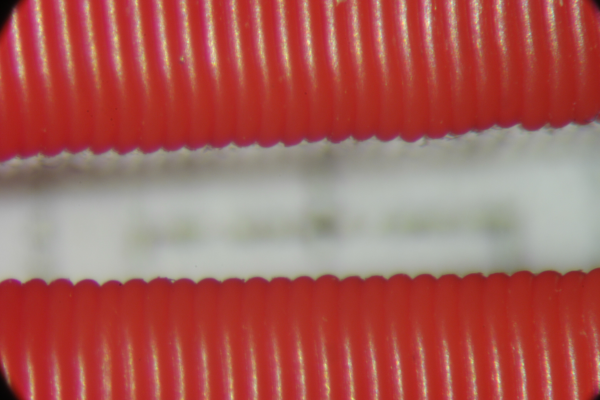
Here's the first test result. The bottom is a part that was printed with the old setup (undercarriage present, no allowance for thermal expansion), the top is the same edge of an identical part printed with the printer modified as described in previous posts to allow thermal expansion of the bed. We are looking at the same corner of the two parts, with the Y axis coming out of the image. The layers are 0.25 mm thick.
It's a little disappointing, but that's what happens when you live on the edge... Note that without a microscope to look at it, the parts look pretty much the same, at least to my getting-old eyes. The part is copy of the limit switch mount I printed when I converted the X axis motor mount to aluminum a couple days ago.
I may try using a larger diameter reference screw and deeper teflon block to screw it into, but I suspect the problem comes from the other end of the Y axis and is mostly a function of the friction/stiction of the preloaded linear guide. More work to come...
Ultra MegaMax Dominator 3D printer: [drmrehorst.blogspot.com]
|
Re: Heat Compensated Bed Support First Test February 28, 2016 10:57AM |
Registered: 8 years ago Posts: 260 |
I was wondering why you still use the spring mounts.
If I understand the design correctly, then the system you now have will completely handle the
expansion. So you can make the rest of the mountings 100% rigid.
I like the idea and I think I will also try this on my P3Steel when everything is working.
Directly mount an aluminum heat bed to the linear bearings on one side, little bit bigger distance between the bearings then default. And on the other side use the linear ball bearing guide rail, to handle the X expansion, mounted in the middle of the headbed to 2 linear slide bearings of the Prusa.
|
Re: Heat Compensated Bed Support First Test February 28, 2016 11:45AM |
Registered: 9 years ago Posts: 1,873 |
|
Re: Heat Compensated Bed Support First Test February 28, 2016 12:53PM |
Registered: 11 years ago Posts: 5,780 |
Quote
amigob
I was wondering why you still use the spring mounts.
If I understand the design correctly, then the system you now have will completely handle the
expansion. So you can make the rest of the mountings 100% rigid.
I like the idea and I think I will also try this on my P3Steel when everything is working.
Directly mount an aluminum heat bed to the linear bearings on one side, little bit bigger distance between the bearings then default. And on the other side use the linear ball bearing guide rail, to handle the X expansion, mounted in the middle of the headbed to 2 linear slide bearings of the Prusa.
I am using the springs because I still need to adjust it. Once everything is working to my satisfaction, I may try it without the springs. If your printer doesn't have a rock solid frame you're going to need the ability to make some adjustments. Springs make that fast and easy.
Ultra MegaMax Dominator 3D printer: [drmrehorst.blogspot.com]
|
Re: Heat Compensated Bed Support First Test February 28, 2016 01:14PM |
Registered: 11 years ago Posts: 5,780 |
Quote
JamesK
It's far from a bad result for a completely new approach - especially one that has removed a whole load of mass from the Y axis.
Thanks, but disappointing just the same. The design is poor from a mechanical engineering point of view- if you think about the stiction of the linear guide bearing blocks, when the reference pushes or pulls the bed, the the other two bearing blocks lag a bit which will probably cause some flex in the bed. Reduced stiction/friction will probably help reduce this problem. The screws and teflon blocks are probably also a little flexible and that stiction/friction in the bearing blocks will cause those other parts to flex too. If the stand-offs weren't so tall the problem would be reduced, but they have to be tall to allow clearance for the drive screw.
Ultra MegaMax Dominator 3D printer: [drmrehorst.blogspot.com]
|
Re: Heat Compensated Bed Support First Test February 29, 2016 11:18PM |
Registered: 11 years ago Posts: 5,780 |
Update: I removed the springs and replaced them with nuts and lock washers, leveled the bed and ran a flatness test at high temperature.
The result is about the same as previous results- the corners droop a little, the bed is slightly bowed at the center.
High temperature (105C) flatness test video
I'll make a video of the same test at room temperature and post a link later.
Ultra MegaMax Dominator 3D printer: [drmrehorst.blogspot.com]
|
Re: Heat Compensated Bed Support First Test March 01, 2016 07:48AM |
Registered: 9 years ago Posts: 1,873 |
|
Re: Heat Compensated Bed Support First Test March 01, 2016 09:15AM |
Registered: 8 years ago Posts: 68 |
After watching the video, one stupid question came to my mind.
Are you sure, you don't measure flex of the printer as you are measuring from extruder to plate? I would suggest putting the dial fixed to table and then run Y axis and compare it to extruder to plate measurements.
If plate is calibrated for extrusion and it isn't parallel to table, readings would be way off. Also if the plate to table says flat bed, then you know you're having flex in machine.
|
Re: Heat Compensated Bed Support First Test March 02, 2016 12:52AM |
Registered: 11 years ago Posts: 5,780 |
Yes, the measurement includes all the flex in the X and Y axis guides as well as flatness of the bed plate. It is possible that what looks like a bowed bed plate is really a sagging X axis. However, considering the mechanical construction of the X and Y axes, the bed plate seems more likely to be the most flexible part responsible for most of the measured deviation from flatness. The X axis is relatively short and has a 1" square tube (1/8" walls) screwed to the linear guide. I haven't tried to calculate its flex, but it should be very small. The Y axis has a 1" thick aluminum plate under its linear guides. If it were sagging, it would make the bed look dished, not bowed.
I don't have any way to check the bed plate flatness independent of the printer. Measuring the bed plate in the context of the printer mechanism is the best way to see how the plate will perform in a printer.
Ultra MegaMax Dominator 3D printer: [drmrehorst.blogspot.com]
I don't have any way to check the bed plate flatness independent of the printer. Measuring the bed plate in the context of the printer mechanism is the best way to see how the plate will perform in a printer.
Ultra MegaMax Dominator 3D printer: [drmrehorst.blogspot.com]
|
Re: Heat Compensated Bed Support First Test March 04, 2016 06:26PM |
Registered: 11 years ago Posts: 5,780 |
Here's the room temperature test: [vimeo.com]
Ultra MegaMax Dominator 3D printer: [drmrehorst.blogspot.com]
Ultra MegaMax Dominator 3D printer: [drmrehorst.blogspot.com]
Sorry, only registered users may post in this forum.
