Home
>
Developers
>
Topic
V2 of the extruder
Posted by JamesK
|
V2 of the extruder March 20, 2016 02:29PM |
Registered: 9 years ago Posts: 1,873 |
I'm slowly working towards a dual extruder setup, so I'm reworking my first extruder into a more compact form so that I can mount two side by side:
I made up the drive-shaft yesterday, it looks a bit complicated but fortunately it doesn't take that long to turn a few different diameters on a shaft. Milling the flats is a bit fiddly, mostly because of the difficulty of clamping the piece in the right orientation.
There's an m3 thread for a retaining nut, a 3/16 section for a small bearing, then 5mm for the mk8 drive gear, 6mm for a larger bearing and the final section is 1/4" to take the large herring bone gear.
Here it is fitted in place
I need to make a new mount to attach the extruders to the carriage, which I'm planning on making out of aluminum angle. I thought I'd print a template to make it easier to drill all the holes, but once I had the template in CAD I thought I might as well beef it up a bit and prototype the entire mount. I printed it without support, so it needs some clean-up but it looks functional, I'll give it a try and see how long it lasts.
The first extruder was never finished and is still using an undersized drive shaft causing both gears to be off centre. I'm hoping that's the reason for the current poor print quality, so I'm looking forward to trying the new extruder with it's machined drive shaft.
The extruders will use the quick change hotends that I described in [forums.reprap.org]
Edited 3 time(s). Last edit at 03/20/2016 02:52PM by JamesK.

I made up the drive-shaft yesterday, it looks a bit complicated but fortunately it doesn't take that long to turn a few different diameters on a shaft. Milling the flats is a bit fiddly, mostly because of the difficulty of clamping the piece in the right orientation.

There's an m3 thread for a retaining nut, a 3/16 section for a small bearing, then 5mm for the mk8 drive gear, 6mm for a larger bearing and the final section is 1/4" to take the large herring bone gear.
Here it is fitted in place

I need to make a new mount to attach the extruders to the carriage, which I'm planning on making out of aluminum angle. I thought I'd print a template to make it easier to drill all the holes, but once I had the template in CAD I thought I might as well beef it up a bit and prototype the entire mount. I printed it without support, so it needs some clean-up but it looks functional, I'll give it a try and see how long it lasts.

The first extruder was never finished and is still using an undersized drive shaft causing both gears to be off centre. I'm hoping that's the reason for the current poor print quality, so I'm looking forward to trying the new extruder with it's machined drive shaft.
The extruders will use the quick change hotends that I described in [forums.reprap.org]
Edited 3 time(s). Last edit at 03/20/2016 02:52PM by JamesK.
|
Re: V2 of the extruder March 20, 2016 08:04PM |
Registered: 9 years ago Posts: 1,873 |
Finished up a new mounting block for the hotend and got it all put together. All the fan mounts need replacing so it's a mess of non-fitting parts at the moment, but enough to try it out
First plastic was abs, second was pla
I stopped the abs halfway through as I'd forgotten to reset the infill from the 40% I used for the mounting bracket. Print quality is much improved now that the gears are running true Not up to the dentist's standards, but much better than before
Just for fun I ran the pla at 120mm/s instead of the 60 I normally use. The corners show quite a lot of overshoot, but overall I'm impressed with the print quality given the speed
I use relatively low acceleration of 1000mm/s2, so for a 20mm test cube the head won't spend much time at 120, but it was still noticeably faster than a normal print!

First plastic was abs, second was pla

I stopped the abs halfway through as I'd forgotten to reset the infill from the 40% I used for the mounting bracket. Print quality is much improved now that the gears are running true
Not up to the dentist's standards, but much better than before
Just for fun I ran the pla at 120mm/s instead of the 60 I normally use. The corners show quite a lot of overshoot, but overall I'm impressed with the print quality given the speed

I use relatively low acceleration of 1000mm/s2, so for a 20mm test cube the head won't spend much time at 120, but it was still noticeably faster than a normal print!
|
Re: V2 of the extruder March 22, 2016 05:33AM |
Registered: 8 years ago Posts: 5,232 |
Looks really good!
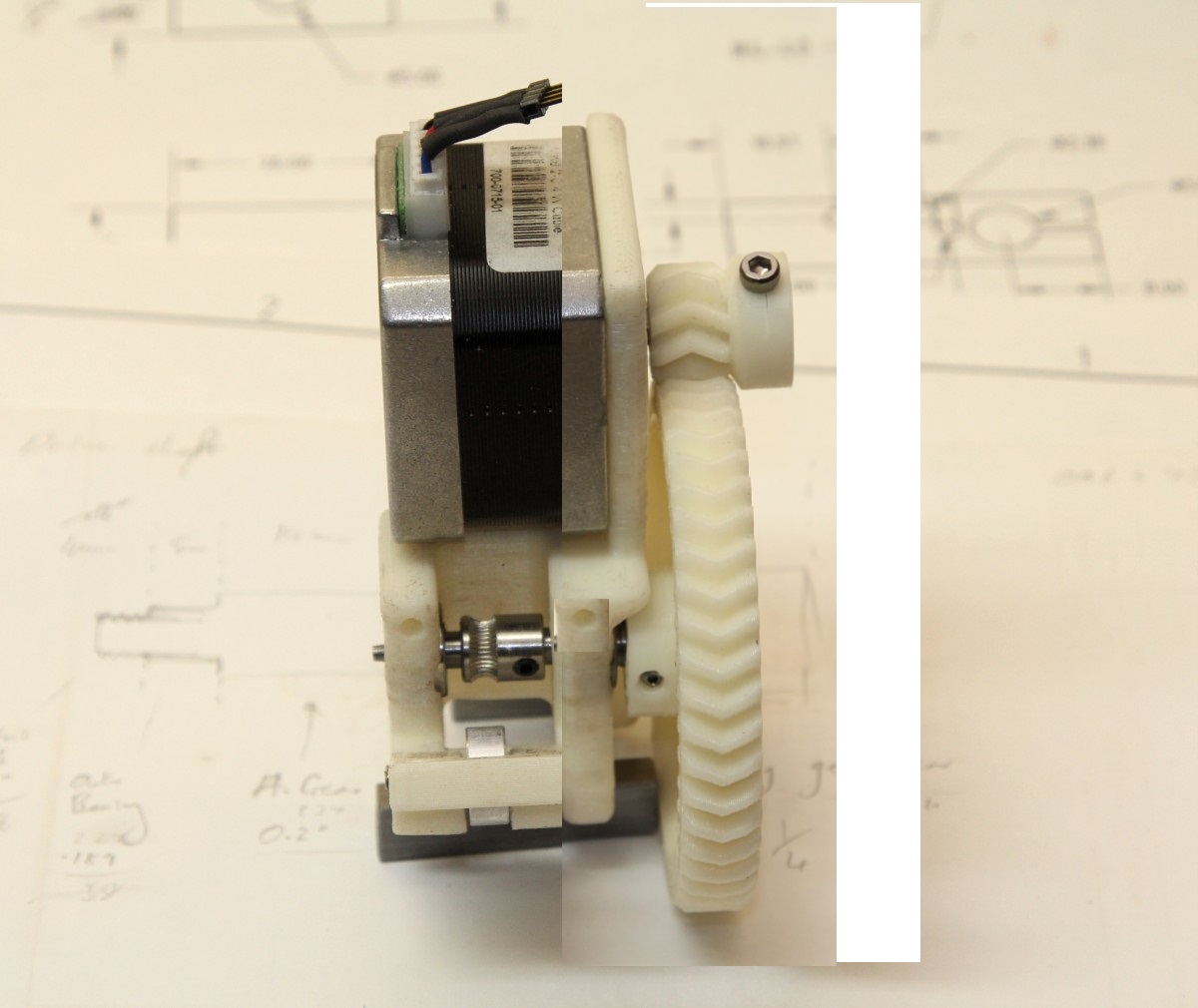
With a NEMAxx pancake the housing could be even shorter, right? The shaft of the idler bearing doesn't have to have a screwhead.
I just photo-chopped one of you pics to show what I mean. I hope you don't mind
Edited 2 time(s). Last edit at 03/22/2016 05:53AM by o_lampe.
With a NEMAxx pancake the housing could be even shorter, right? The shaft of the idler bearing doesn't have to have a screwhead.
I just photo-chopped one of you pics to show what I mean. I hope you don't mind
Edited 2 time(s). Last edit at 03/22/2016 05:53AM by o_lampe.
|
Re: V2 of the extruder March 22, 2016 06:41AM |
Registered: 9 years ago Posts: 1,873 |
Yes, exactly. Now you've done that photoshop, you've made me want one I guess the narrowest you could go would be the length of the hobbed gear plus two bearings and the depth of the big herringbone gear.
Amigob has been working on a reduced wades setup for dual extruders with the motors facing the other way. That's probably a better setup [forums.reprap.org]
For compact dual extruders the itty bitty looks pretty goodt: [www.thingiverse.com]
I used the new extruder to print the frame for the left hand side - it felt very reprap The idler bearing isn't wide enough, it feels like the filament is going to escape at any moment, so I'm going to double the width for the next iteration. I've also got rid of the gap between the wall at the gear side and the wall that supports the idler door. With the gap gone and a 45 degree chamfer under the idler door mounts the frame prints without supports now.
Edited 1 time(s). Last edit at 03/22/2016 06:47AM by JamesK.
I guess the narrowest you could go would be the length of the hobbed gear plus two bearings and the depth of the big herringbone gear.Amigob has been working on a reduced wades setup for dual extruders with the motors facing the other way. That's probably a better setup [forums.reprap.org]
For compact dual extruders the itty bitty looks pretty goodt: [www.thingiverse.com]
I used the new extruder to print the frame for the left hand side - it felt very reprap
The idler bearing isn't wide enough, it feels like the filament is going to escape at any moment, so I'm going to double the width for the next iteration. I've also got rid of the gap between the wall at the gear side and the wall that supports the idler door. With the gap gone and a 45 degree chamfer under the idler door mounts the frame prints without supports now.Edited 1 time(s). Last edit at 03/22/2016 06:47AM by JamesK.
|
Re: V2 of the extruder March 22, 2016 07:08AM |
Registered: 8 years ago Posts: 260 |
|
Re: V2 of the extruder March 22, 2016 07:13AM |
Registered: 8 years ago Posts: 260 |
|
Re: V2 of the extruder March 22, 2016 08:07AM |
Registered: 9 years ago Posts: 1,873 |
Quote
amigob
Biggest problem I have now is that I can't get the new X carrier printed. It pulls the tape of the glass when it is curling.
With PETG? I thought that wasn't supposed to have much warp. If you have spare glass you could try glue-stick instead of tape. That seems to work well with most plastics once you find the right temperature (bed & nozzle) for the first layer.
Quote
does the overshoot also reduce when you decrease acceleration ?
I haven't played much with acceleration yet. I did find that the corners improve if I increase the XY jerk value (which I also have set very low normally). I suspect that the pressure in the nozzle always lags behind what's needed, so the bigger the difference between the printing speed and the lowest cornering speed the more excess plastic gets laid down, causing the bulge in the corners. For real parts I always put the largest radius fillet on the corners that I can to reduce the speed changes, but the test cube is straight edges.
|
Re: V2 of the extruder March 26, 2016 06:08PM |
Registered: 9 years ago Posts: 1,873 |
Well, I got the second extruder finished and mounted, and the printer rewired to drive it. I thought that was the difficult bit done, but man this dual extrusion stuff is a whole new level of difficult. I seem to be hitting limitations and bugs at every turn, not to mention stuff that is just plain harder, like one nozzle dragging the first layer that was just put down by the other one!
I designed a simple vernier-like calibration part (kind of odd that I couldn't find one, I'll put this up on pinshape when I get a moment) and that let me measure the offsets fairly quickly. But no luck so far with an actual print.
The offsets are right when the middle pins of each side line up (the '0' pins). If there's a residual error you read along the line until you find the best match, and the number gives the error in units of .1 mm.
Cura seems very limited in it's dual extruder support, it assumes that both extruders are using the same filament diameters and extrusion factor. No good for me as I'm using 1.75 on one side and 3mm on the other. Slic3r seems more capable, it can cope with the different filament settings, but the integration with Repetier host seems a bit 'lacking'. I can't get the slic3r settings for using different extruders for perimeters and infill to work if I run it from Repetier, I have to run it stand-alone for that. I'm just running a test cube now that was done that way - so far so good!
I want to try the 2-colour tree frog, but it won't slice in sic3r, and guess how I found out about that limitation of Cura Trying to repair the tree frog with Netfabb now...
I designed a simple vernier-like calibration part (kind of odd that I couldn't find one, I'll put this up on pinshape when I get a moment) and that let me measure the offsets fairly quickly. But no luck so far with an actual print.


The offsets are right when the middle pins of each side line up (the '0' pins). If there's a residual error you read along the line until you find the best match, and the number gives the error in units of .1 mm.
Cura seems very limited in it's dual extruder support, it assumes that both extruders are using the same filament diameters and extrusion factor. No good for me as I'm using 1.75 on one side and 3mm on the other. Slic3r seems more capable, it can cope with the different filament settings, but the integration with Repetier host seems a bit 'lacking'. I can't get the slic3r settings for using different extruders for perimeters and infill to work if I run it from Repetier, I have to run it stand-alone for that. I'm just running a test cube now that was done that way - so far so good!
I want to try the 2-colour tree frog, but it won't slice in sic3r, and guess how I found out about that limitation of Cura
Trying to repair the tree frog with Netfabb now...|
Re: V2 of the extruder March 26, 2016 06:26PM |
Registered: 8 years ago Posts: 260 |

|
Re: V2 of the extruder March 26, 2016 07:21PM |
Registered: 9 years ago Posts: 1,873 |
Heh, don't let me put you off with all the problems I'm having. Other people seem to get this stuff working, so I'm sure we'll get there.
Here's the link to the calibration model: [pinshape.com]
The test cube worked out ok, so I'm making progress.
Here's the link to the calibration model: [pinshape.com]
The test cube worked out ok, so I'm making progress.
|
Re: V2 of the extruder March 26, 2016 08:48PM |
Registered: 9 years ago Posts: 1,873 |
|
Re: V2 of the extruder March 27, 2016 06:09AM |
Registered: 8 years ago Posts: 5,232 |
I've tried the frog too with my dual Bowden.
I was able to print it "somehow" after I added a solid single color 1st layer. Otherwise the first layer didn't stick.
The idea of a tilting dual extruder was born at the same time, because the unused nozzle always scraped across the print like you described.
I was able to print it "somehow" after I added a solid single color 1st layer. Otherwise the first layer didn't stick.
The idea of a tilting dual extruder was born at the same time, because the unused nozzle always scraped across the print like you described.
|
Re: V2 of the extruder March 27, 2016 11:53AM |
Registered: 9 years ago Posts: 1,873 |
Well, the frog printed, but it's hardly what you'd call a quality print. In fact it's down right ugly!
Part of the problem was that I didn't use any of the multi-extruder ooze prevention settings, so there were a lot of blobs added to the print as the non-printing nozzle passed over a perimeter. Interestingly there was for more ooze from the white 1.75mm filament than the red 3mm one, which given the 3mm nozzle has a far bigger melt volume was a surprise. Most of the rest of the problem I think came from over-extrusion. The red is a new roll that I haven't got dialled in yet - it's amazingly different compared to the white which was my first roll of abs, and I also had 'extra length after restart' set, and it looks like the value was too high - and there was a LOT of retraction going on in this print! Oh, and I guess the fact that my part cooling fans aren't functional at the moment didn't help with the overhangs either. I print my abs hot to compensate for lack of enclosure, and then use gentle fan settings for bridging and small layers.
I still have lots to do (and learn!) to get this working well.
A tilting extruder set-up sounds interesting. I searched the forum and there have been some very interesting ideas. With the frustration of watching my first layers getting ploughed up I started thinking about a simple spring loaded retraction mechanism, but now I have the heads levelled better there doesn't seem to be quite so much need. I'll see how things work out and keep it in mind as something to possibly come back to.
|
Re: V2 of the extruder March 29, 2016 01:44PM |
Registered: 9 years ago Posts: 1,873 |
Just got the email to say that Pinshape is shutting down, so I've put the calibration test on Thingiverse: [www.thingiverse.com]
Sorry, only registered users may post in this forum.