Home
>
Developers
>
Topic
A new 3D printer design
Posted by TheHackerArtist
|
A new 3D printer design May 26, 2017 01:07AM |
Registered: 9 years ago Posts: 67 |
Hi RepRapers,
I've been working on a new 3D printer design for just over a year now and wanted to share my project. I will be spending most of my summer on this and plan to offer workshops building this printer by July.
This thread will serve as a log as I go through the testing and refinement of the printer.
If you have feedback, comments, ideas or know of similar work, feel free to share your thoughts here.
A bit about me: I have been building and designing 3D printers for about 4 years now. I am currently completing my undergrad in mechanical engineering.
The intention behind this 3D printer was to build a machine that:
Is mechanically robust, so as to push Jerk and the resulting printing speed as high as possible without introducing ghosting. In numbers : Reliable and ghosting free 300mm/s printing with PLA
Is fast and easy to assemble so the machine could be assembled in a workshop setting with ease and maintained without hassle
Is made of as many reusable parts as possible so if the printer becomes obsolete over time all it's parts can be simply repurposed for other projects
Can reliably print flexible materials
Has fast bed heating times and can heat up to temperatures suitable for polycarbonate printing (150C)
Can easily swap nozzles for printing at various sizes and with various materials without risk of cloging
Is simple and actually works rather than having a bunch of nice features and gimmicks, the emphasis is on reliability, speed and print quality before being user friendly
All while keeping costs as low as possible
Can print human size object ( like a big mask, a forearm brace or a tibia replica)
I have innovated but have certainly borrowed ideas from this forum, various other sources and printers on the market. I have done a poor job at keeping track of my references and influences. I recognize this project would not be possible without the contribution of others.
Here are some features of the printer:
MECHANICAL
flat aluminium T6 heat bed (heat spreader)
Steel sheet printing surface, for flexibility, thermal conductivity and ease of detaching print.
4 point manual bed leveling
2020, 2040 and 2060 T Slot aluminum framing
2020, 2040 and 2060 V Grooved aluminium framing from Open Build
High torque Nema 17 motors (96 Oz-in)
Steel wire and Spool drive system
Build plate supported at both ends
E3D Titan Direct Drive Extruder. For ease of swaping the hot end
Acrylic side sheets
260mm by 390mm printable area and 350mm print height
ELECTRICAL
Main wired (120V) silicon heating pad, heats up to 150C in a few minutes, 60C in a few seconds
Megatronics 2.0 board
A4988 Stepper drivers
360W PSU
Safety emergency push button
Thermal shutdown safety on heated bed
SOFTWARE
Repetier Firmware on printer
Windows on computer
A bit on my design decisions:
The aluminium sheet metal bed spreads the heat from the silicon heat pad very well, while maintaining flatness and a good rigidity. The bed is covered with a thin flexible sheet of steel. This sheet can be removed easily like a backing pan, cools down fast and prints essentially pop off. This is much simpler than covering the bed with any form of adhesive or surface and having to mess around with boroscilicate glass that always ends up chipping.
The steel wire system was to make tensioning of the wires as simple as possible and eliminate backlash which often seems two issues with the typical GT2 pulley and belt systems.
The wire system also makes it simple to introduce a pulley system that doubles the motor torque and steps pers mm.
The Open build V groove frame system allows to combine the framing element and guidance elements, elminating parts. Linear bearings often have play. The rolling wheel's tension on the aluminium extrusion can be manually adjusted with ease, ensuring there is no play.
The direct extrusion Titan extruder system from E3D seems to have made its name, it is reliable, easy to swap the V6 hot end and simple to assemble.
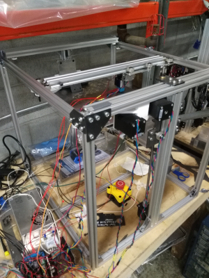
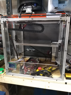
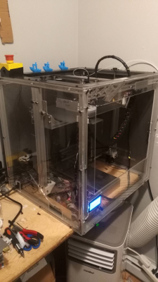
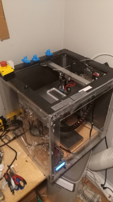
Here's an image of the current state of the printer
The electrical wiring needs some better management but I'm still and building and R&D phase.
That's for my first post!
I will be completing mechanical assembly and my first tests tomorrow (5/27/2017) I hope.
Edited 2 time(s). Last edit at 05/26/2017 10:24AM by TheHackerArtist.
|
Re: A new 3D printer design May 26, 2017 02:13AM |
Registered: 11 years ago Posts: 5,780 |
Some of it looks pretty good, but I gotta say, you're a mech engineering student, you've been building printers for 4 years, and you still use 4 screws to level a print bed?
96 oz-in is readily available in NEMA-17 size motors. NEMA-23 motors are going to vibrate more and make a lot more noise.
Printing at 300 mm/sec is an admirable goal. Will you be incorporating some special technology to control the molten plastic after it leaves the nozzle? You're trying to use very high acceleration which means rapid start and stop for the extruder carriage, but the molten plastic has its own momentum. I have a hard time believing you'll be able to get an acceptable quality print at that sort of speed/acceleration/jerk.
Kudos for skipping the glass on the bed, but do common printing plastics stick to steel?
Steel wire motion systems look interesting.
Quality linear guides don't have any play and are much more compact than wheels riding in the t or v slots. I don't think there's much price difference between the two.
One recommendation- I know you're just testing at this point, but do something to secure the cables at the extruder carriage- the thermistor leads will only bed a couple times before they break and then you'll be shut down until a new thermistor arrives.
Ultra MegaMax Dominator 3D printer: [drmrehorst.blogspot.com]
|
Re: A new 3D printer design May 26, 2017 02:52AM |
Registered: 10 years ago Posts: 14,672 |
Looks nice, but I see some potential electronics issues (I'll leave comments on the mechanics to others):
- A4988 drivers are a very poor match for Nema 23 motors because they are only good to about 1.2A or a little more if well-cooled. Most Nema 23 motors are rated at 2.8A or more, although I have seen a few high-inductance types that are rated at 2.0A. If you really want to use Nema 23 motors, you need either a Duet WiFi or Duet Ethernet controller (good for motors up to 2.8A or a bit more) or external drivers.
- Also, the combination of Nema 23 motors with only x16 microstepping will produce a lot of noise and vibration. As digitaldentist pointed out, high torque Nema 17 motors would be an alternative. Higher microstepping will make the printer smoother and quieter.
- Make sure the stepper driver supply voltage is sufficient to maintain torque up to your target maximum movement speed. See [duet3d.com].
- I presume you will be using a Volcano hot end. An ordinary hot end won't melt plastic fast enough at your target speed.
HTH David
Edited 1 time(s). Last edit at 05/26/2017 02:54AM by dc42.
Large delta printer [miscsolutions.wordpress.com], E3D tool changer, Robotdigg SCARA printer, Crane Quad and Ormerod
Disclosure: I design Duet electronics and work on RepRapFirmware, [duet3d.com].
|
Re: A new 3D printer design May 26, 2017 10:27AM |
Registered: 9 years ago Posts: 67 |
Thanks for the feedback!
I am indeed using Nema 17 motors, I apologize for noting they were Nema 23, not sure what went through my mind. But those are good points I'll definitely not venture in the Nema 23 realm than!
@ The digital dentist
There's an assumption behind the choice of 4 point leveling. I understand only three points are needed to define a plane. That said, from my understanding the reason why rectangular tables have 4 legs is that if you don't want someone sitting on the corner to end up with his food on his lap. In a 3 point leveling system, I am assuming the two unsupported corners will lower down if force is applied to them. I assumed this could impact layer height consistency on larger prints that approach the edges of the built plate.
That's an interesting point about plastic having it's own momentum. I agree this will probably limits the system's speed for a desired quality. I don't have any special technology other then a direct drive system that has less hysteresis than a bowden system. Has some research been done in the past at these speeds?
@DC42 yes a volcano hot end will be used at these speeds.
With the bed heated at their glass transition temperature, PLA, PLA/PHA and Co polyester all adhere well with a bit of hair spray. Note the print surface was sanded with rough sand paper. And the prints do easily pop off the bed as it cools.
Hmm, for linear bearings, the prices I was looking at for quality linear bearing were $30 per bearing. Are you referring to a particular system? The other advantage of wheels is that it allows larger tolerance gaps in the frame because the distance the wheels are at can be manually adjusted with ease during assembly.
The thermostat used is a cartridge by E3D so It's less fragile but I'll make sure too secure everything before I start testing.
Edited 1 time(s). Last edit at 05/26/2017 10:55AM by TheHackerArtist.
|
Re: A new 3D printer design May 26, 2017 12:36PM |
Registered: 8 years ago Posts: 5,232 |
The volcano hotend is a "double sided sword". On one side the bigger nozzle diameter requires less force, but on the other side it requires more heating power the faster it got fed. Some people reported slower print speed with the 1-1.2mm nozzles due to temp-drop.
Edited 1 time(s). Last edit at 05/26/2017 12:38PM by o_lampe.
Edited 1 time(s). Last edit at 05/26/2017 12:38PM by o_lampe.
|
Re: A new 3D printer design May 26, 2017 01:51PM |
Registered: 9 years ago Posts: 67 |
@ o lamp
E3D offers 0.4mm nozzle diameter and for high speeds and highly detailed prints, that's what I'll be testing with, but I see your point. There are higher Wattage heater cartridges out there if I realize power is an issue. Then that comes with the complication of tuning PID control for different loads.
Cheers
|
Re: A new 3D printer design May 26, 2017 06:20PM |
Registered: 11 years ago Posts: 5,780 |
Yes, unsupported corners of thin material will sag under its own weight by an amount that will render the plate useless as a print bed surface, which is why so many cheapo printers have 4 leveling screws (that and a complete lack of engineering input, and a target market that won't spend more than $300 for a printer). Adjusting those screws almost guarantees that you're going to bend the plate and the support structure in most designs, so it's still unprintable over most of the surface without clamping a piece of glass to it to try to flatten it.
For the size of bed you listed, a piece of 6- 8 mm cast tooling plate would be flat enough to print on, edge to edge, unless that first layer has to be 50 um thick, and no glass will be needed. Since the bed moves in the Z axis, it's pretty easy to make a support structure that allows the plate to expand when heated without creating any lateral forces on the leveling screws. Nothing is going to bend, the system will be stable, and shouldn't need releveling once set up. That means no autoleveling, and so no bed sensor or wiring is needed. A thin layer of PEI for the print surface will have prints sticking reliably, or you can use your steel sheets if they'll sit flat on the surface. A >=0.4W/cm^2 heater, preferably line powered, will ensure reasonable heat-up time.
Slicers put prints at the center of the bed plate. I suppose it is possible that a print will be lopsided and the majority of the weight could end up at an unsupported corner, but that would occur slowly, as the mass of the print increased, so the error would have the layers slowly getting a little thicker at the corners as the mass increases. If you support the bed at the corners the center is going to sag under print mass. The bed is going to sag a little under print weight no matter what you do. A piece of tooling plate isn't going to sag enough to mean anything in any application where a 3D printed part is an acceptable solution.
If you scour the ebay listings for linear guides, it isn't too hard to find good deals on quality used or NOS Japanese/German/American (IKO, THK, NSK, Bosch, etc.) made units. A Taiwanese company, HiWin, makes quality guides, but there are so many poor quality knock-offs from China, I'd avoid ordering them unless you get them directly from HiWin. Once I know how long the rails need to be and how many bearing blocks they need to have, I start shopping. The size of the rails aren't critical- loads in a 3D printer are orders of magnitude below the rated loads for even small linear guides, so I buy whatever is cheap, long enough, and has enough bearing blocks. 15-24 mm wide rails seem most common. Once I have the rails and blocks I design them into the machine. I typically pay $30-70 for rails with bearing blocks. Here's an example of NOS rails with 2 blocks for <$60 shipped, though it's hard to be sure of the length of the rails without asking the seller- [www.ebay.com] You can find stuff like this pretty easily.
Edited 2 time(s). Last edit at 05/26/2017 06:24PM by the_digital_dentist.
Ultra MegaMax Dominator 3D printer: [drmrehorst.blogspot.com]
|
Re: A new 3D printer design May 26, 2017 08:18PM |
Registered: 11 years ago Posts: 1,049 |
Please read thread
[forums.reprap.org]
Digital Dentist know the subject well?
How many printers designed and built in 4 years?
Mechanical engineering -- what year, school?
If you want to engineer this: (this is what any system engineered project would do)
Needs, purpose, wants (concept of Operation)
Requirements (include cost) (speed, accuracy, resolution, operation, maintenance, risk, life cycle)
Requirements validation (do requirements meet purpose)
Trade studies, make buy decisions, use known design / new
Design (design testing, risk reduction, prototype)
Design validation ( does design meet requirements)
Development
Integration and test
Requirements verification
Deployment, Operation
------ What requirement drives 300mm/sec?
------ Squirting hot polymer may be a great limitation?
------ 360W PS to heat hot end to shoot out hot polymer fast a bit low?
------ 12v 24v system?
------ why limit controller and firmware?
How is tensioning a steel wire easier and easier to eliminate backlash?
How does a wire system makes it simple to introduce a pulley system that doubles the motor torque and steps per mm?
How does a steel wire system insure a motor step rotation distance gets to the extruder movement?
(trade study -- wire vs belt vs leadscrew)
Core XY drive?
The brackets on frame look whimpy! Frame rigidity --- resolution, accuracy nice print requirement
extruder mass, start, stop accelerate / decelerate --- whole lot of shakin goin on?
Linear bearings often have play What linear bearings have you used that have play?
How does rolling wheel's tension on the aluminum extrusion manually adjusted easy and ensure there no play.?
Will you be using bearing eccentics?
Don't over constrain. Thermal expand / contract
Lots of design / build mine fields may be avoided by reading DD development
But I think the build is going forward without the thought process?

|
Re: A new 3D printer design May 27, 2017 09:54PM |
Registered: 10 years ago Posts: 39 |
Quote
the_digital_dentist
Adjusting those screws almost guarantees that you're going to bend the plate and the support structure in most designs
I'll take the unpopular position that 4 screw isn't necessarily an error. When you're done leveling, each of the 4 point should be equidistant form the nozzle at the commanded height. If (and that's a very big if) your Y carriages have no twist, then your bed will necessarily be flat. Of course, how you level and how you mount the bed make more of a difference with 4 points, and will take longer than three points.
Also, for home-brew quality machines, getting the y rod pair perfectly coplanar in a typical machine and getting them to stay that way through temperature swings and moving the machine around is not easily done. If there's a bit of twist to your xy plane and you don't have grid bed probing, then flexing the bed a bit actually can help get the offset to the z head more constant.
Which brings up a point - maybe most machines do it wrong. If you have a perfectly flat bed, perhaps you should have 4 point leveling, not three point, on the xy setup, not the bed, so you can get it coplanar with the bed. That would let you adjust out any twist.
All that said, the diminutive printer I'm sitting next to has 3 point leveling.

|
Re: A new 3D printer design May 27, 2017 10:02PM |
Registered: 10 years ago Posts: 39 |
|
Re: A new 3D printer design May 28, 2017 12:34AM |
Registered: 11 years ago Posts: 5,780 |
What you're saying makes no sense.
You are misunderstanding a fundamental concept. The printer's axes, defined by the guide rails, need to be orthogonal because the CAD and slicer software assume that they are. The reason the bed is made adjustable and not the XY mechanism is because the orthogonality of the axes must be maintained. If you tweak the XY mechanism to make it parallel to the bed, you tilt the XY plane relative to the Z axis. Tilting the bed doesn't change the relationship between the printer's axes. Tilting the XY mechanism does. If you destroy the orthogonality of the axes, you can't make an accurate print. When you level the bed, you're making it parallel to the printer's XY plane so that the first layer of the print has a good opportunity to stick.
The guide rails in any axis need to be parallel, period. If they are not, you don't fix it by bending the bed (or the mechanism), you fix it by making the rails parallel. You're right about one thing. It can be difficult to get end supported rails parallel to each other and keep them that way. Even if you manage to get them parallel, they are going to flex. That's one of several advantages of using fully supported rails, and especially linear guides. Mounting them on a flat plate reduces the possible errors to one degree of freedom. Once you know they are in the same plane, making them parallel is as easy as using a rigid spacer to align them. Flex is minimal with fully supported guides because you have the flat plate supporting the rails.
I don't see any point in building a 3D printer yourself if you don't bother correcting the design errors commonly found in kits (and assembled printers). It's a lot easier and cheaper to just buy a kit and accept whatever stupid design choices the kit maker made to minimize cost.
Ultra MegaMax Dominator 3D printer: [drmrehorst.blogspot.com]
|
Re: A new 3D printer design May 29, 2017 03:22PM |
Registered: 11 years ago Posts: 1,049 |
DD "I don't see any point in building a 3D printer yourself if you don't bother correcting the design errors commonly found in kits (and assembled printers). It's a lot easier and cheaper to just buy a kit and accept whatever stupid design choices the kit maker made to minimize cost."
It's called unencumbered by thought process - or anybody's else though process
and lately "the rule" not the exception.

It's called unencumbered by thought process - or anybody's else though process
and lately "the rule" not the exception.

|
Re: A new 3D printer design June 01, 2017 01:55AM |
Registered: 9 years ago Posts: 67 |
@Cozmicry, thanks for reminding me the importance of being thorough.
The fact is I'm not entirely sure what all the requirements are. I want to get a prototype out asap and do some real world testing rather than spend time refining a theoretical model. I also need to get a mvp out for a beta workshop asap so I can hear feedback from on the field use. I'm not designing a spaceship or a car factory, nobody's going to die if an axis starts twisting, and I'm not loosing several millions if I over engineer something. I can just iterate and come out with modifications on earlier printers if need be. Being slightly ambiguous about my requirements was a choice because of time constraint. I should definitely define that more clearly once I have a working prototype and feedback. It's true I have not done a great job at noting all my design decisions, research and experiences along the way, but keep in mind a one man team is developing this for the time being.
How is tensioning a steel wire easier and easier to eliminate backlash?
-With crimped ferrules and and a tensioning hook and screw system I can install and adjust tension on the wires in less that 5 minutes. One of the big issues that kept coming back in my research was belt being hard to connect to carriage and tension properly. There is no backlash in a spool and wire system because there is no possibility for slip and there is zero play at the mating point of the wire with the spool on the motor.
How does a wire system makes it simple to introduce a pulley system that doubles the motor torque and steps per mm?
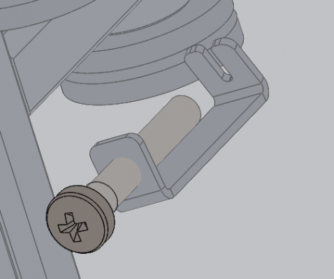
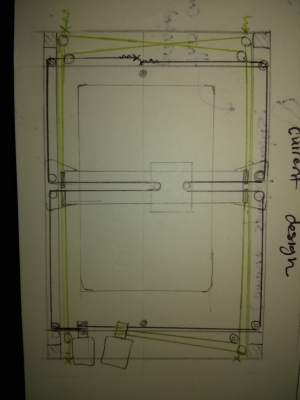
-hmm here's a not so clear image of the wire system. The attachment point of the wire is on the frame and it moves the carriages through bearings.
How does a steel wire system insure a motor step rotation distance gets to the extruder movement?
-Sorry for the ambiguity, the extruder is a direct drive and doesn't use steel wire, only the X and Y carriage are driven by steel wire and a spool system. Z axis uses a lead screw.
(trade study -- wire vs belt vs leadscrew) -- Just intuition and reading through other user stories, a wire is as simple as it gets so there is less place for tolerance issues
Core XY drive?
-It's not a core XY nor an H-bot. Each motor controls one axis, not sure what the system I use is called. I inspired myself from a commercial pick and place machine.
The brackets on frame look whimpy! Frame rigidity --- resolution, accuracy nice print requirement
-You're right, clearly I did not think this through, the frame is super flimsy as it stands. I have modified the printer framing so it is enclosed and all 6 axis are rigid (see below)
extruder mass, start, stop accelerate / decelerate --- whole lot of shakin goin on?
-The Y axis mass is a bit less than a kilogram, there should not be much shaking as there is no loose parts and the new frame is rigid in all 6 axis
I have build four Wilson TS, all with a wire drive system though, and 8 3D printers of my own design ( see here)
The details of my studies is irrelevant to this conversation. please send me a PM if you want to get in touch personally.
I've narrowed down the software to Repetier because that is the firmware I am most familiar with and Repetier host is a great host software. Same goes for windows environment. What is your preferred host software, slicer and firmware and why?
The controller choice is not limited, the megatronics is great because it is compatible with thermocouples, I am familiar with 8bit controllers and the stepper driver are easy to swap.
@ The digital dentist
Good points.
I've gone ahead and modified the Z holding plate and the bed design to a three point leveling system. I will be ordering some parts today.
I finished mechanical assembly and noticed some issues with the current design.
The Z carriage sags as there is not enough support from the wheels on the opposing side - I have added a second lead screw that will be connected to the first one through a GT2 belt and pulley system.
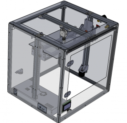
Here is a render of the current design:
Only the face with the door and the face where the electronics enclosure sits will be in acrylic. The other faces will be in aluminium or steel -- I still have to decide, any thoughts on that? I have a good metal laser cut supplier.
@Tray
The min diameter of curvature is about 15 milimeters for the wire I use (0.8mm, pvc coated 7x7 steel wire) so I have matching bearings (625ZZ V grooved). That should not be an issue.
As for the linear bearings, I need consistency in my supply chain if I will be designing this to be produced in a workshop setting. I can't just look at deals on ebay. I am convinced a V wheels system is the most consistent and cheapest option for motion with zero play.
Edited 2 time(s). Last edit at 06/01/2017 01:58AM by TheHackerArtist.
|
Re: A new 3D printer design June 01, 2017 07:42AM |
Registered: 11 years ago Posts: 5,780 |
In the last image it looks like the Z axis rails don't connect to the frame members at the top and bottom. The frame rigidity would be greatly increased if those were connected. As drawn, if you have to take off the side panel off to access the electronics, you'll have to take the Z axis apart. That will be a PITA and will require realigning the machine when you put it back together. Putting electronics in the bottom of the machine is fine, but assumes that the Z axis is operational to allow access. If there's a problem with the Z axis motor driver or cable, how will you access the electronics if the bed is sitting at the bottom of the machine?
On the X axis there don't appear to be any wheels running on the outside of the rails. It's easy to put panels on the front and back of the frame without those wheels, but what does that do to the performance of the X axis? This specific problem is why I have avoided using those wheels for printer design. They make it difficult to design a frame-integral enclosure, and I like enclosing printers so I can print ABS. Do you intend to close the top so you can print ABS? If so, you'll want to move the electronics out of the enclosed area (heat+electronics=bad result). If you're not enclosing the machine to print ABS, maybe you don't need the panels at all, if the frame is rigid. They will add rigidity, but they will also make servicing the machine a bit more troublesome.
Ultra MegaMax Dominator 3D printer: [drmrehorst.blogspot.com]
|
Re: A new 3D printer design June 01, 2017 02:45PM |
Registered: 11 years ago Posts: 1,049 |
Your X, Y mechanism is somewhat like a drafting parallel rule system and insanity
How does this system lend itself to high speed?
This is a unique system and you have no heritage or other like systems to rely on.
Does Marlin / Repetire firmware support this system?
It appears that a pure Y move requires X system to move just to keep it stationary?
Looks like paramount requirement is to keep motors outside the enclosure?
"I need consistency in my supply chain if I will be designing this to be produced in a workshop setting."
Produceability is a distant requirement?
Don't know if thousands would want a unique drive system
and a design that has not been ---- engineered?

|
Re: A new 3D printer design June 06, 2017 03:44PM |
Registered: 8 years ago Posts: 622 |
To the OP. Firstly welcome to these forums and I wish you well with your endeavours. Can you clarify what you mean by this statement.
"Is mechanically robust, so as to push Jerk and the resulting printing speed as high as possible without introducing ghosting.................."
As an engineering student you must know that the first derivative of position with respect to time is velocity, the second is acceleration and the third is Jerk. That is to say Jerk is the rate of change of acceleration and manifests itself, as the name implies, in a sudden and somewhat violent change of position. So the above statement is rather contradictory in that it implies high jerk will somehow reduce or negate "ghosting".
On the other hand, 3D printers do not use Jerk in the physics sense but rather it is the instantaneous speed change used when doing small segmented moves such as simulated arcs but still, a high jerk setting will likely lead to "ringing".
Perhaps it's your own definition of the terms "Jerk" and "ghosting" which is leading to the confusion. What is your definition of those terms?
Also regarding print speed. I have seen many, many, many posts and printer designs from people who think they have designed, or are in the process of designing the "Ferrari" of all printers. Unfortunately, the limiting factor with FFD 3D printers is how fast we can melt filament. Even with an E3D Volcano, it's not that fast. So, it's a bit like building a racing car capable of 0-60 in under 5 seconds with a top speed of 200+ mph but only being able to use it in a 30mph speed limit with heavy traffic.
[somei3deas.wordpress.com]
[www.youtube.com]
|
Re: A new 3D printer design July 06, 2017 12:29AM |
Registered: 9 years ago Posts: 67 |
@ Cozmicray
The motors are kept outside the frame to keep part count low.
I don't understand your pessimism about the drive mechanics. I probably did a poor job at communicating exactly how it's wired up but the X motor does not need to move while the Y axis moves. both motors control one axis and are independent. All torques cancel out so no twist is induced on the middle aluminum extrusion. I just did my first print ever today at 60mm/s and 0.2 layer height (Finally!) and the result is extremely good. I haven't even tweaked print settings and anything else yet. There is practically no ghosting! (Jerk settings were at 20mm/s)
The is the printer, it needs a bit of tidying up but everything is there.
The box you see at the back is a hepa filter. A vacuum sucks the air in at the nozzle rather then blowing on the extruded filament.
@ dekingman
Yes, I meant Jerk as defined in most firmware as the instantaneous speed change. By ghosting I mean ringing, essentially wobbles in the XY plane following a sudden change in direction.
To clarify my statement, the aim is to reduce print time as much as possible for a given level of quality.That level of quality is set at a point where ghosting would not be noticeable, say, less than 0.05mm wave amplitude in the XY plane. Because a low jerk results in high speeds rarely being attained on geometries that result in change of print head direction over short distances, the higher the jerk setting can be pushed without introducing ringing in the mechanical structure, the lower the print time.
Your argument for the ultimate limiting factor being the speed at which plastic can flow through the nozzle holds but I don't believe that is the first limiting factor. The first limiting factor is Jerk being too low to ever have the printer attain the max extrusion speed. That's where building a sturdy motion system becomes key, because if you want to increase jerk, you need the mechanical sturdiness to ensure your structure can support the resulting forces.
as a side note, I have done some testing with just the extruder and I can get roughly 18 mm cube per second max volume flow rate with a 0.4mm nozzle for PLA. This corresponds to a max print speed before filament grinding of 240mm/s for PLA on 0.2mm height or 480 mm per second on a layer height of 0.1mm.
I'll be back with some more results as I tweak the print settings and test with various speeds and materials.
MY CURRENT ISSUE:
I cannot get the SD card to work on my megatronics 2.0 running Repetier.
I decided to switch over to Marlin and currently cannot upload the firmware because of some sort of compiling issue.
Essentially, the boards.txt file of the arduino IDE has to be modified to include the megatronics board. I can upload repetier firmware using arduino IDE 1.0.5 but I cannot compile Marlin with Arduino IDE 1.0.5. When I switch to IDE 1.8.3, suddenly I get a compiling error due to the board.txt file.
Has anyone been able to upload marlin to megatronics 2.0 using arduino IDE version 1.8.3 ?
Cheers!
|
Re: A new 3D printer design July 06, 2017 07:30AM |
Registered: 11 years ago Posts: 5,780 |
I quit using 8 bit boards years ago because of all the compiling problems. Once you get it working, it will work until the next Arduino IDE update which will break it again. In two years, when you want to change extruders, you'll be swearing because you have to locate an out of date IDE and plug-ins and then get it all compiling again. Save yourself a lot of time and frustration and get a 32 bit controller. It well worth the extra $ up front. You won't have to replace busted motor driver modules, either.
I'm trying to replace the extruder on a Taz 3 printer at the makerspace and having no end of problems getting the damned IDE to compile the firmware. So frustrating! It should be a simple change, and on a 32 bit board, all it would take is updating the config file with a text editor.
Edited 1 time(s). Last edit at 07/06/2017 07:32AM by the_digital_dentist.
Ultra MegaMax Dominator 3D printer: [drmrehorst.blogspot.com]
|
Re: A new 3D printer design July 06, 2017 03:41PM |
Registered: 11 years ago Posts: 335 |
What velocity, acceleration, and jerk/juncdev are you using?
I've been thinking about how extruders might perform with instantaneous velocity changes. Obviously maintaining constant speed while printing is good, since the extruder pressure can remain constant, but is there a point where the printer starts and stops so quickly that extruder pressure lags behind the printer motion?
As far as I'm aware traditional pressure advance only has an effect during periods of acceleration/deceleration and therefore would not help. You might just need to start and stop extruding X milliseconds before commanded.
|
Re: A new 3D printer design July 06, 2017 09:29PM |
Registered: 11 years ago Posts: 1,049 |
Please a photo of your drive system.
Can't understand napkin drawing.
How is it an independent X, Y system?
"both motors control one axis and are independent." HUH?
Each motor controls an axis and are independent?
What does motor location have to do with part count?
What firmware? What type of drive is selected in firmware?
If an engineer can't communicate via clear words or drawings
he will get stripped camel when design was for a horse?
Perhaps sign up for Technical writing / speaking course?
Perhaps a CAD course?

@ Cozmicray
The motors are kept outside the frame to keep part count low.
I don't understand your pessimism about the drive mechanics. I probably did a poor job at communicating exactly how it's wired up but the X motor does not need to move while the Y axis moves. both motors control one axis and are independent. All torques cancel out so no twist is induced on the middle aluminum extrusion. I just did my first print ever today at 60mm/s and 0.2 layer height (Finally!) and the result is extremely good. I haven't even tweaked print settings and anything else yet. There is practically no ghosting! (Jerk settings were at 20mm/s)
Can't understand napkin drawing.
How is it an independent X, Y system?
"both motors control one axis and are independent." HUH?
Each motor controls an axis and are independent?
What does motor location have to do with part count?
What firmware? What type of drive is selected in firmware?
If an engineer can't communicate via clear words or drawings
he will get stripped camel when design was for a horse?
Perhaps sign up for Technical writing / speaking course?
Perhaps a CAD course?

@ Cozmicray
The motors are kept outside the frame to keep part count low.
I don't understand your pessimism about the drive mechanics. I probably did a poor job at communicating exactly how it's wired up but the X motor does not need to move while the Y axis moves. both motors control one axis and are independent. All torques cancel out so no twist is induced on the middle aluminum extrusion. I just did my first print ever today at 60mm/s and 0.2 layer height (Finally!) and the result is extremely good. I haven't even tweaked print settings and anything else yet. There is practically no ghosting! (Jerk settings were at 20mm/s)
|
Re: A new 3D printer design July 06, 2017 10:17PM |
Registered: 11 years ago Posts: 5,780 |
The print looks pretty good, but if you're specifically looking for ringing, sharpen the corners of the print. Rounded corners are always going to have less ringing than square corners. Also put a few holes in the sides of the print. They will really show what the ringing of the machine is like. Maybe something like this...
I don't know if I've ever seen a convincing argument about the source of and ultimate solution to ringing. It could be belts stretching and acting like springs, it could be the moving mass interacting with the stepper motor which is acting like a spring, or a combo. Which contributes more probably depends on a lot of variables- moving mass, motor torque, belt type and length, the rigidity of the whole machine, acceleration and jerk/junction deviation, and print speed. I suppose minimizing moving mass would be a good place to start...
Edited 1 time(s). Last edit at 07/06/2017 11:14PM by the_digital_dentist.
Ultra MegaMax Dominator 3D printer: [drmrehorst.blogspot.com]
|
Re: A new 3D printer design July 13, 2017 11:20AM |
Registered: 7 years ago Posts: 270 |
Can you print a quality 3DBenchy in less than an hour?
PS.: I like that your design is only using aluminum plates and extrusions. It appears that everything can be adjusted and design has high tolerance to variability of the parts. This may be a pretty successful kit printer.
One thing that would concern me would be X axis side load on the rollers causing premature wear and increased slop with use.
Edited 1 time(s). Last edit at 07/13/2017 11:38AM by newbob.
|
Re: A new 3D printer design August 24, 2017 01:23AM |
Registered: 9 years ago Posts: 67 |
Alright, it's been some time. I've continued working on the project, amongst other things. I am now working in a new space.
I solved the issue with the board and can print with the on board SD card with no issue.
I have not kept an exact log but I have been printing trouble free for about 30 hours of print now.
@the digital dentist, I have ordered a 32 bit controller (the ultratronics) and will get familiar with it.
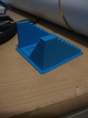
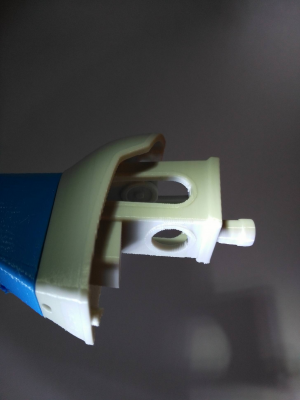
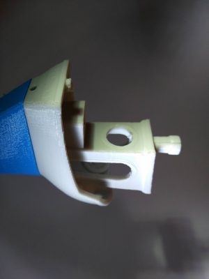
@newbob Got it done! it took roughly 50 minutes for this one to print out. I am happy with the result but there is still space for improvement. Feel free to comment on the print quality.
The full set of twenty images with various focus can be found here:
Imgur image set link
The full set of twenty images with various focus can be found here:
Imgur image set link
And a little video
YouTube Video of 3DBenchy
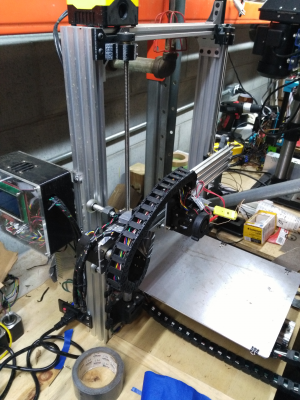
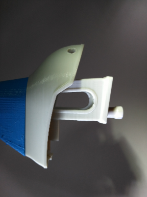
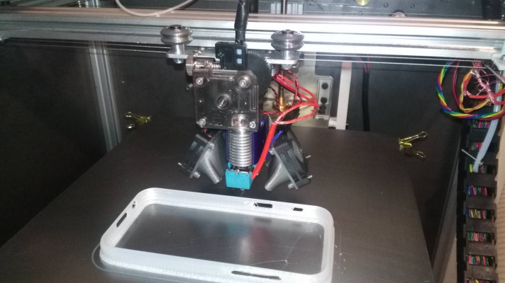
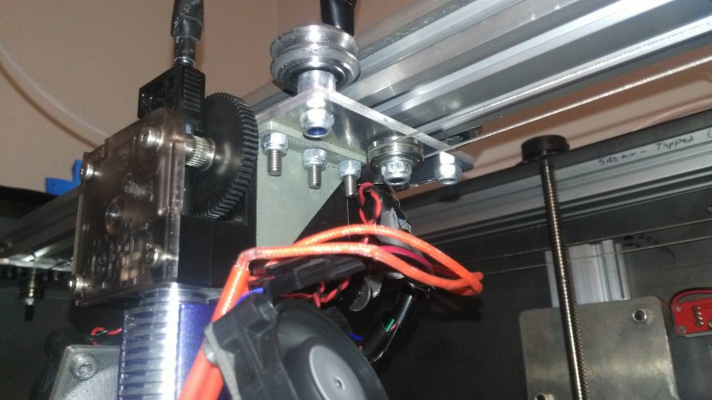
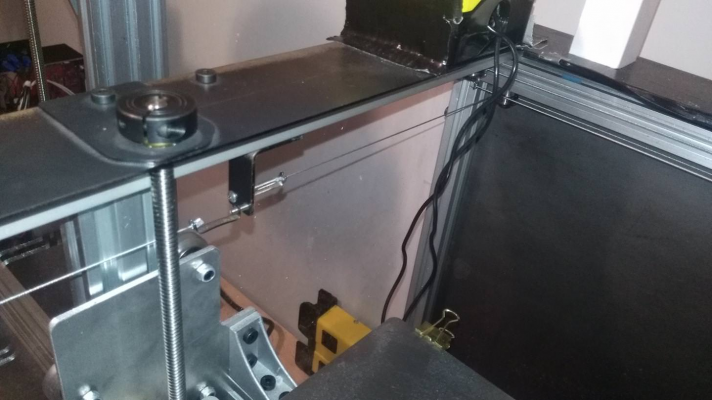
Here are a few picture of the actual printer in it's current state.
I think the biggest issue now is the Z axis mechanism, I get a barely noticeable waviness in the Z axis which I attribute to inconsistent inter-layer distance. I will be getting some better quality leadscrews and GT2 pulleys/belt, these were purchased to test the concept and I have no clue what the tolerance on these parts are. The Z axis motor is also poorly held in place.
Once that is done though I think I've got a pretty solid machine.
The wiring also needs some clean up, I spent little time designing for the cabling/connections but I will be making things cleaner. Any thoughts on the best types of connectors to use and tips for wire management?
As for the serviceability of the machine's electronics, the electronics box slide-locks in place, so it can be removed from its location under the Z axis easily and the top of the enclosure removed to expose all the connections.
I received some new blower fans for the hepa filter but have not done much testing on that end yet. I have concluded I will need to both blow air on the part and suck the air in. I'll need some thinking and testing to get proper air flow so I can cool parts and recuperate most of the fumes.
Edited 2 time(s). Last edit at 08/24/2017 10:44AM by TheHackerArtist.
I solved the issue with the board and can print with the on board SD card with no issue.
I have not kept an exact log but I have been printing trouble free for about 30 hours of print now.
@the digital dentist, I have ordered a 32 bit controller (the ultratronics) and will get familiar with it.
@newbob Got it done! it took roughly 50 minutes for this one to print out. I am happy with the result but there is still space for improvement. Feel free to comment on the print quality.
The full set of twenty images with various focus can be found here:
Imgur image set link
| Jerk [mm/s] | 15 |
| Acceleration[mm/s^2] | 4000 |
| Outside Perimeter Speed [mm/s] | 32 |
| Print Speed[mm/s] | 80 |
| Layer Height[mm] | 0.2 |
| Slicer Software | Simplify 3D |
| Infill[%] | 20 |
The full set of twenty images with various focus can be found here:
Imgur image set link
And a little video
YouTube Video of 3DBenchy
Here are a few picture of the actual printer in it's current state.
I think the biggest issue now is the Z axis mechanism, I get a barely noticeable waviness in the Z axis which I attribute to inconsistent inter-layer distance. I will be getting some better quality leadscrews and GT2 pulleys/belt, these were purchased to test the concept and I have no clue what the tolerance on these parts are. The Z axis motor is also poorly held in place.
Once that is done though I think I've got a pretty solid machine.
The wiring also needs some clean up, I spent little time designing for the cabling/connections but I will be making things cleaner. Any thoughts on the best types of connectors to use and tips for wire management?
As for the serviceability of the machine's electronics, the electronics box slide-locks in place, so it can be removed from its location under the Z axis easily and the top of the enclosure removed to expose all the connections.
I received some new blower fans for the hepa filter but have not done much testing on that end yet. I have concluded I will need to both blow air on the part and suck the air in. I'll need some thinking and testing to get proper air flow so I can cool parts and recuperate most of the fumes.
Edited 2 time(s). Last edit at 08/24/2017 10:44AM by TheHackerArtist.
|
Re: A new 3D printer design August 25, 2017 07:41AM |
Registered: 7 years ago Posts: 270 |
|
Re: A new 3D printer design August 25, 2017 08:33AM |
Registered: 9 years ago Posts: 67 |
@newbob
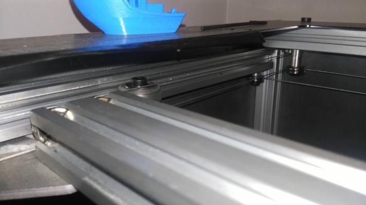
Yes, that's actually the Y axis, according the frame of reference I set up in firmware. Metal rollers were used there because I ran out of PC ones and the machine was used in a dirty environment. PC rollers should minimize this but it's still a concern. Cleaning up that rails isn't too complicated though.
I'll try to have a video of it running once it's fully assembled and tiedied up.
|
Re: A new 3D printer design August 25, 2017 10:11AM |
Registered: 11 years ago Posts: 5,780 |
What's wrong with the Z axis in cheap printers? They use bent threaded rods to lift the X axis on thin, flexible, end-supported guide rails. As the screws turn, they put lateral force on the guide rails, which are happy to flex, displacing the X axis slightly, creating Z wobble in the prints.
You have very rigid Z axis guidance- bends in the screws aren't going to flex the t-slot that you're using for guides. But those guides are anchored to thin, flexible, and cracked on the left side, acrylic sheet. I think your Z axis problems will go away if you anchor both ends of the Z axis "guide rails" to the frame, metal to metal.
Ultra MegaMax Dominator 3D printer: [drmrehorst.blogspot.com]
Sorry, only registered users may post in this forum.
