Home
>
Developers
>
Topic
Vertical X-axis standard !And Contest W/ Prize Updates
Posted by bryanandaimee
|
Vertical X-axis standard !And Contest W/ Prize Updates August 28, 2011 09:53PM |
Registered: 13 years ago Posts: 632 |
In keeping with the recent standards discussion, I think the time is ripe for at least one standard. It looks like a fair number of reprap variants are looking at vertical x axis smooth rod arrangements (emaker huxley, mixtape mendel, reprap.org/wiki/X-carriage-struder, etc.) I'm soon to be thinking about that choice myself on the test tube mendel, and leaning toward a vertical x axis. Rod spacing is a critical dimension, and I think it would be good to get that standardized so that vertical format extruders could interchange between variants. I think also that it should be a bit wider spacing than the standard horizontal spacing (mendel and prusa) to allow for the motor to protrude through the x smooth bars if desired.
Edited 3 time(s). Last edit at 12/28/2011 11:42AM by bryanandaimee.
Edited 3 time(s). Last edit at 12/28/2011 11:42AM by bryanandaimee.
|
Re: Vertical X-axis standard August 28, 2011 11:38PM |
Registered: 13 years ago Posts: 632 |
|
Re: Vertical X-axis standard August 29, 2011 12:19AM |
Registered: 13 years ago Posts: 78 |
Hey Bryan,
I don't know if you've seen mixtape mendel... i think standardized spacing is great though. But i feel the real future is in fully parameterized modeling. Right now this constrains mixtape mendel to be developed in openscad, but it will allow for infinite hardward configs. Right now i think x rod spacing center to center is defined as a bushing diameter, 2 ziptie heights, the motor body width and a bushing radius, with 1/2 going to each wall around the bushing. It comes out to around 60. Definetly check out mixtape. I spent and am spending a good portion of my time deciding the relationships and mathematical constants. I try to base things off their closest hardware component and some scaling factor, normally 2 or 4.
Btw, what is test tube mendel?
Edited 1 time(s). Last edit at 08/29/2011 12:19AM by tesla893.
-Steve
|
Re: Vertical X-axis standard August 29, 2011 12:40AM |
Registered: 13 years ago Posts: 632 |
Yes. I've been watching the mixtape mendel design. I like it a lot. I'm also a fan of parametrizing design as much as is reasonable, though I don't yet have the CAD skills to do it in my own designs yet. It seems like a parametrized design could still easily have some set dimensions. Just use that as the starting point and subtract the other factors from it rather than adding up the other to get the separation?
I do think though that it is a good idea to have a few critical dimensions be set to allow for cross pollination without too much trouble. The spacing between smooth rods on the x axis seems to me to be one of those critical dimensions. Most of the other dimensions seem to me to be much less critical to interoperability. At least in the mendel/prusa world, the extruder is where a lot of the action is right now. I doubt there would be so much development if designers had to make multiple versions to fit mendel vs. prusa. That is mitigated quite a bit in the horizontal x axis world by the separation of the carriage and the extruder into two different parts, but I think the integration of the two is a natural development step especially for vertical x axis designs. Once the extruder is integrated with the carriage, (or even if someone wants to do that as a design variant/upgrade) the separation between rods becomes critical to interoperability.
test tube mendel is here [reprap.org]
It's getting there. I'm still trying to decide if I want to do a horizontal x axis first so I don't have to redesign the x carriage and extruder, or if I'm going to jump in with both feet and make the x axis vertical to begin with.
So I'm guessing you would vote for something like 60mm on center?
Bryan
|
Re: Vertical X-axis standard August 29, 2011 05:11AM |
Registered: 13 years ago Posts: 615 |
I agree with you. I was thinking about that too when imagining to add then a geared-carriage-struder (or in case someone want to) 
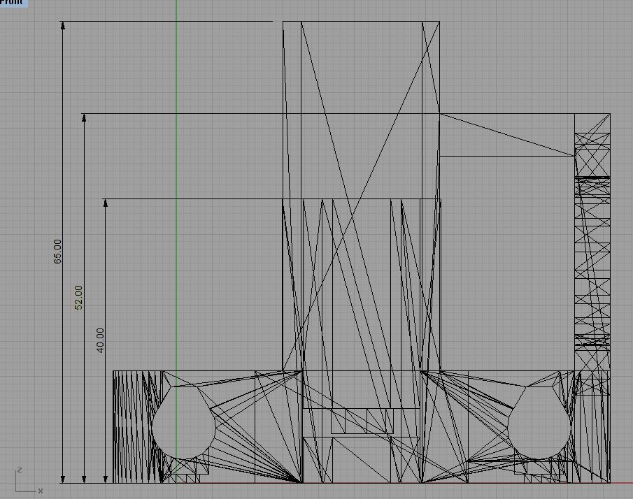
Thanks to having the same dimension I seems able to put my x-ends on both Prusa and Sells Mendel (they share the same spacing of 28,5mm from center to center in the x-end.stl from prusa, and measured with a ruler on my classic mendel)
In my case the distance between vertical smooth rods center-to-center (for the v1b) is 65.7mm on the model 65,23 mm in real.
The main constraint was to be able to put the motor between the rods plus a little margin to snap the LM8UU, add the zip-ties, and let the belt pass under the motor.
(my strict minimum could have been 50mm if I putted the LM8UU on the side of the motor, but it would be difficult for the other things, and losing space in x-travel in profit of z-travel)
So, after this first prototype, I'll say 60-65mm, regarding how you deal with the belt.
Edited 1 time(s). Last edit at 08/29/2011 05:39AM by Emmanuel.
Thanks to having the same dimension I seems able to put my x-ends on both Prusa and Sells Mendel (they share the same spacing of 28,5mm from center to center in the x-end.stl from prusa, and measured with a ruler on my classic mendel)
In my case the distance between vertical smooth rods center-to-center (for the v1b) is 65.7mm on the model 65,23 mm in real.
The main constraint was to be able to put the motor between the rods plus a little margin to snap the LM8UU, add the zip-ties, and let the belt pass under the motor.

(my strict minimum could have been 50mm if I putted the LM8UU on the side of the motor, but it would be difficult for the other things, and losing space in x-travel in profit of z-travel)

So, after this first prototype, I'll say 60-65mm, regarding how you deal with the belt.
Edited 1 time(s). Last edit at 08/29/2011 05:39AM by Emmanuel.
|
Re: Vertical X-axis standard August 29, 2011 05:30AM |
Registered: 12 years ago Posts: 2 |
Hi Bryan,
Good to see the Test Tube Project still cooking.
>could you post your smooth rod spacing for the x axis and perhaps any design constraints
The 1X2 x-rails have a 60mm spacing c-c.
Here are the main reasons I went with the vertical x-axis on the 1X2:
1)A vertical x-axis does not have to worry about fitting the print head between the rails.
This makes head changes and hotend designs easier because the head can slide out unobstructed.
The carriage also does not need a hole in it for the hotend.
A secondary head like a plotter arm can be mounted on the backside of the rails with low overhang in both directions.
I found it easier to design a vertical carriage with all the bolts going in one plane.
2) If the mount points on the z-axis is the same to give equal stability, the total height of a vertical x-axis is not any greater than a horizontal x-axis. So the horizontal design is not saving any travel.
If the z-leadscrew-nut is one point of contact and each rail has two points of contact, the horizontal arrangment should tend to use more support material as it has more points of contact spanning a distance from the center.
|
Re: Vertical X-axis standard August 29, 2011 10:53AM |
Registered: 13 years ago Posts: 632 |
Yes, I agree there are a lot of features of vertical x axis designs that seem to be an improvement. In addition to your excellent reasoning, I think the printed parts can be smaller and at the same time produce a stiffer assembly. I think it should be possible to shave an hour or two or possibly even more off the total print time of the x assembly and carriage/extruder if the extruder has an integrated carriage.
Looks like a good standard might be 60 or 65 mm center to center. Do you guys think it would be better to make it 65 to allow a little more flexibility, or is 60 mm enough? Also are there any other designs that you know about that are doing vertical x axis that haven't been mentioned? I've tried to contact the designers I know about through the forums or thingiverse etc.
Looks like a good standard might be 60 or 65 mm center to center. Do you guys think it would be better to make it 65 to allow a little more flexibility, or is 60 mm enough? Also are there any other designs that you know about that are doing vertical x axis that haven't been mentioned? I've tried to contact the designers I know about through the forums or thingiverse etc.
|
Re: Vertical X-axis standard August 30, 2011 10:21AM |
Registered: 13 years ago Posts: 228 |
Emmanuel Wrote:
-------------------------------------------------------
> Thanks to having the same dimension I seems able
> to put my x-ends on both Prusa and Sells Mendel
> (they share the same spacing of 28,5mm from center
> to center in the x-end.stl from prusa, and
> measured with a ruler on my classic mendel)
>
Very, very nice work you are doing, Emmanuel.
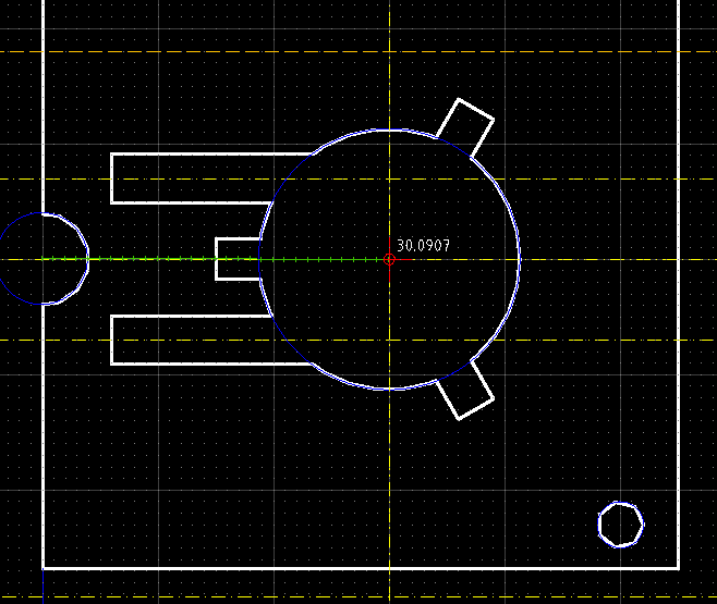
I am slightly puzzled by one remark: you mention the distance between the axis of the vertical smooth Z rod and the vertical screw to be 28.5 mm on a both Mendel and on a Prusa Mendel.
Some time ago, I sliced an old stl for the mendel to check that dimension, and I get a consistent 30 mm (plus or minus the segmentation artifacts).
I haven't been able to slice the more recent Prusa Z motor beds to check that spacing (import fails in openscad), but I suspect something similar there.
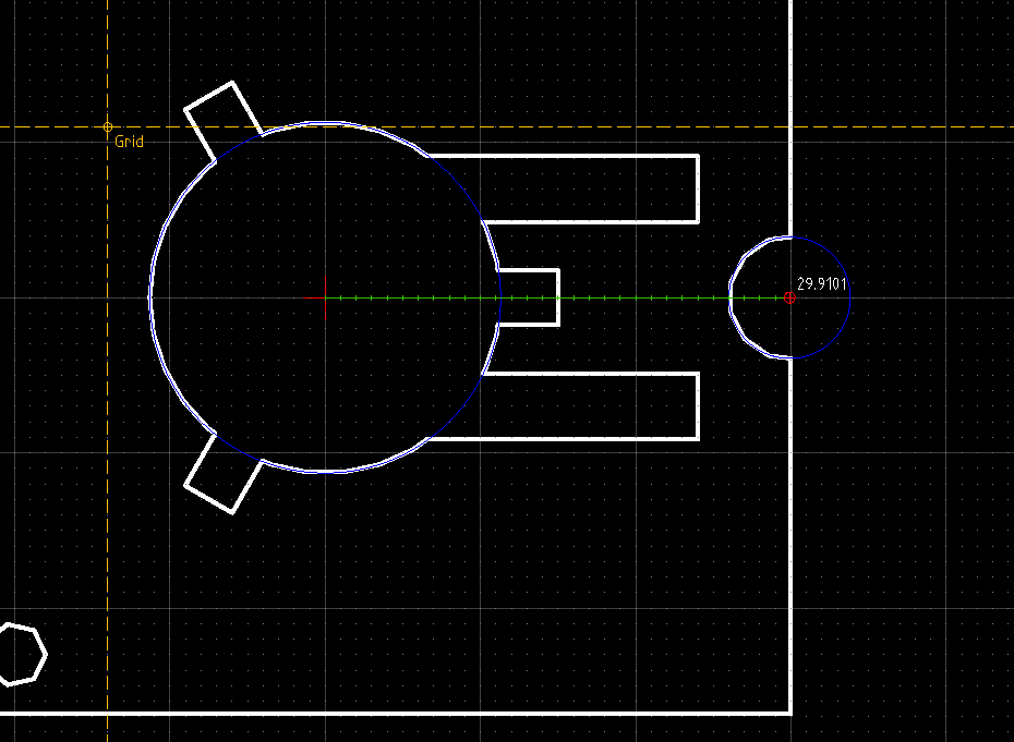
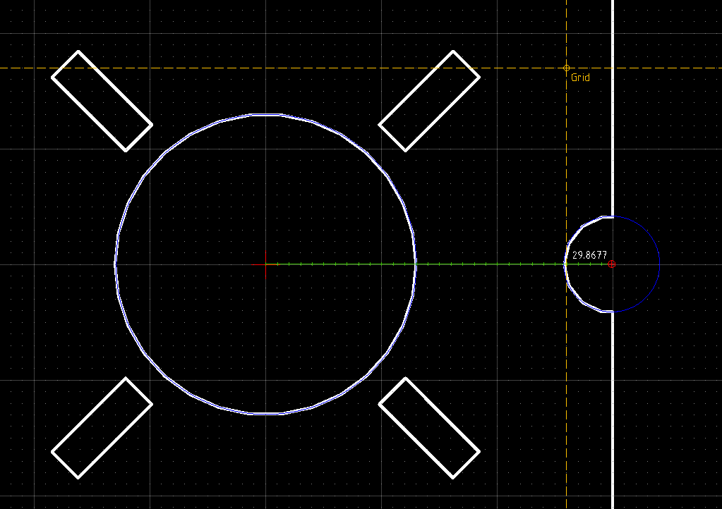
Edit: and here are the measurements taken from the official prusa mendel files. 29.8677 is nearest of 30...
That's one of the shortcomings related to not having a reference set of old-fashioned but so-accurate 2D plans. I think we should get serious and draw some.
Edited 6 time(s). Last edit at 08/30/2011 12:36PM by Lanthan.
-------------------------------------------------------
> Thanks to having the same dimension I seems able
> to put my x-ends on both Prusa and Sells Mendel
> (they share the same spacing of 28,5mm from center
> to center in the x-end.stl from prusa, and
> measured with a ruler on my classic mendel)
>
Very, very nice work you are doing, Emmanuel.
I am slightly puzzled by one remark: you mention the distance between the axis of the vertical smooth Z rod and the vertical screw to be 28.5 mm on a both Mendel and on a Prusa Mendel.
Some time ago, I sliced an old stl for the mendel to check that dimension, and I get a consistent 30 mm (plus or minus the segmentation artifacts).


Edit: and here are the measurements taken from the official prusa mendel files. 29.8677 is nearest of 30...

That's one of the shortcomings related to not having a reference set of old-fashioned but so-accurate 2D plans. I think we should get serious and draw some.
Edited 6 time(s). Last edit at 08/30/2011 12:36PM by Lanthan.
Attachments:
open | download - mendel_idler_cut.png (22.5 KB)
open | download - z-idler-belt_cut.dxf (24.2 KB)
open | download - mendel_motor_cut.png (27.1 KB)
open | download - z-motor-belt_cut.dxf (27.8 KB)
open | download - prusa_zmotormount.dxf (22.7 KB)
open | download - prusa_zmotormount.png (37 KB)
open | download - z-motor-mount.scad (1.8 KB)
|
Re: Vertical X-axis standard August 30, 2011 11:27PM |
Registered: 13 years ago Posts: 632 |
OK, I thought I was going crazy for a second, but I finally caught on that some of the discussion is on the threaded z rod to smooth z rod now. That seems like it might be another dimension that might benefit from some sort of standard. If Prusa and Sells mendel are both the same there's probably no reason to change. I vote for 60mm on the vertical smooth x bars and 30 mm on the z axis smooth to threaded. 60 on x only because it seems that that will cause the least grief due to changes in design, and the current prusa Z/X axis assembly is already about 60 mm tall so very little loss of Z travel if we keep it about that tall. There will still be some loss since 60 mm center to center is taller than 60 mm total.
|
Re: Vertical X-axis standard August 31, 2011 03:30AM |
Registered: 13 years ago Posts: 228 |
@brianandaimee: yes, indeed, if we are redesigning the X ends we should also take into account the Z rod to smooth bar distances given in those pieces.
May I suggest the following:
We should also take into account the possibility of parametrically setting different (higher) smooth rod diameters. It is becoming clearer and clearer that with higher speeds, belt tension and energy levels in the machine, 8 mm rods might not "cut it", so the possibility to "evolve" the basic design to use 10 and up to 12 mm smooth rods should exist.
This implies of taking into account the additional margin needed for (optional) LM12UU bushings in the design.
I had a look at the wiki "Mendel Drawings" page, it is quite out of date and incomplete, many drawings do not show the distance between axes. I'll try posting the few designs and slicings I have.
Also someone has made -a long time ago- a set of drawings for a mendel repstrap with the same basic measurements (OverlapStrap), as far as I remember the distances were clearly indicated.
|
Re: Vertical X-axis standard August 31, 2011 04:33AM |
Registered: 12 years ago Posts: 1,611 |
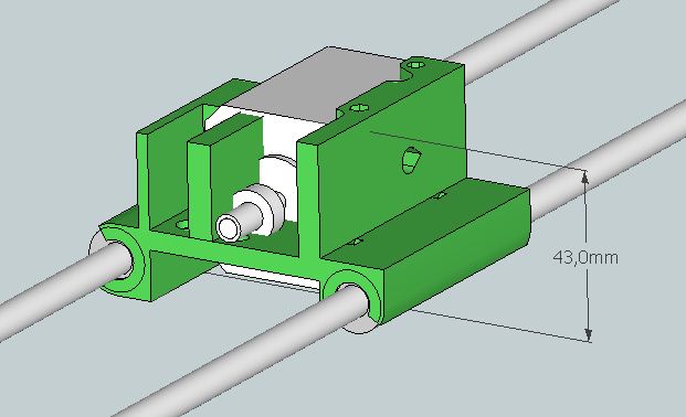
On the subject of the vertical X-axis distance, I think 60mm is too small. Not withstanding a move to larger rods as Lanthan mentions above, NEMA17 motors are 42.3mm wide and LM8UU bearings are 15mm. I think you would want a compact design with the bearings above and below the motor; Greg Frost's x-carriage is 80mm wide (without fan mount, though depending on extruder and fitting it will be wider), and as Emmanuel shows above, with the bearings each side it's 95mm wide already. To start going too wide and losing X-axis distance negates other advantages. Also, if you have the bearings either side of the motor, you constrain the motor to being in the middle of the carriage.
A bare minimum size is going to be over 60mm, with only a couple of mm between the motor and bearings and no space for the belt - one of the key advantage of this layout is the the belt is between the bars. If you want to make it parametric such that you could go for 10 or even 12mm rod, it's going to need to be even bigger; LM10UU diameter is 19mm, LM12UU diameter is 21mm.
70mm is going to be a more realistic number to shoot for. Even at this height I reckon you're losing less than 10mm off the Z travel, compared to a horizontally-barred extruder.
I think Emmanuel has done a great job so far, though someone is going to have to remodel it in Openscad to make it parametric!
|
Re: Vertical X-axis standard August 31, 2011 08:01AM |
Registered: 13 years ago Posts: 615 |
@Lanthan Thanks, my design is not perfect but I'm looking to try it in the coming weeks
And oops, you're right, it's closer to 30mm (I agree, if only we had a clear set of reference...I started with a sketchup model of the Sells Mendel before realizing its rods were even at 33mm and then measured mine and reduce it to 28,5mm)
(29-30 depending of how you put the bushing)
But it seems to fit perfectly on my mendel ^^' I'll mount it on it during the coming weeks to confirm that...
I measured 65mm and less for the top of the motor and top of the part where a nut is trapped
But the extruder will bump on the rods of the frame before the x-ends.
I stopped this print few cm later because of that :
Now my x-ends are as high as the classic ends on the Sells Mendel (75ish) but in the vertical axis the upper smooth-rod will touch the frame-vertex before the x-ends will reach the top rods-clamp of the frame. So their height is not really a problem (I supposed it was even better for stability to put the bearings far from each other).
If we count the height of the extruder+motor (on a greg-wade by example), the distance from the center of the rods to the highest point is around 75mm if not more (I'll confirm that tomorrow).
And, in any case, at a certain point in Z, the motor will start bumping on the side of the frame (that's also why it's good to put in between the rods, to diminish its protruding permitting to go a little higher)
If the goal was to achieve the maximum z-travel (that's maybe another topic), I think the most compact solution is a direct-drive extruder like the x-carriage-struder but on a classical horizontal x-axis.
(I just turned the motor to illlustrate what I mean
(we can already put a motor between the x-rods on the Sells Mendel, hmm maybe I'll try that too^^)
We lose the convenient features of a vertical axis in favor of more Z travel, I hesitated to do that first and then the vertical config, but I rarely build things that tall, and my actual prototype seems already a little shorter than my open-x-carriage plus greg-wade.
To conclude: in comparison of the actual extruders/carriages/x-ends, 65mm between vertical x-rods will probably not result in a loss of z-travel (I will try to take pictures of that).
@droftart : Thumbs-up for parametric designs !
And oops, you're right, it's closer to 30mm (I agree, if only we had a clear set of reference...I started with a sketchup model of the Sells Mendel before realizing its rods were even at 33mm and then measured mine and reduce it to 28,5mm)

(29-30 depending of how you put the bushing)
But it seems to fit perfectly on my mendel ^^' I'll mount it on it during the coming weeks to confirm that...
Quote
bryanandaimee
the current prusa Z/X axis assembly is already about 60 mm tall so very little loss of Z travel if we keep it about that tall
I measured 65mm and less for the top of the motor and top of the part where a nut is trapped

But the extruder will bump on the rods of the frame before the x-ends.
I stopped this print few cm later because of that :

Now my x-ends are as high as the classic ends on the Sells Mendel (75ish) but in the vertical axis the upper smooth-rod will touch the frame-vertex before the x-ends will reach the top rods-clamp of the frame. So their height is not really a problem (I supposed it was even better for stability to put the bearings far from each other).
If we count the height of the extruder+motor (on a greg-wade by example), the distance from the center of the rods to the highest point is around 75mm if not more (I'll confirm that tomorrow).
And, in any case, at a certain point in Z, the motor will start bumping on the side of the frame (that's also why it's good to put in between the rods, to diminish its protruding permitting to go a little higher)
If the goal was to achieve the maximum z-travel (that's maybe another topic), I think the most compact solution is a direct-drive extruder like the x-carriage-struder but on a classical horizontal x-axis.
(I just turned the motor to illlustrate what I mean

(we can already put a motor between the x-rods on the Sells Mendel, hmm maybe I'll try that too^^)
We lose the convenient features of a vertical axis in favor of more Z travel, I hesitated to do that first and then the vertical config, but I rarely build things that tall, and my actual prototype seems already a little shorter than my open-x-carriage plus greg-wade.
To conclude: in comparison of the actual extruders/carriages/x-ends, 65mm between vertical x-rods will probably not result in a loss of z-travel (I will try to take pictures of that).
@droftart : Thumbs-up for parametric designs !
|
Re: Vertical X-axis standard August 31, 2011 12:24PM |
Registered: 13 years ago Posts: 601 |
Lanthan Wrote:
-------------------------------------------------------
> @brianandaimee: yes, indeed, if we are redesigning
> the X ends we should also take into account the Z
> rod to smooth bar distances given in those
> pieces.
>
> May I suggest the following:
> We should also take into account the possibility
> of parametrically setting different (higher)
> smooth rod diameters. It is becoming clearer and
> clearer that with higher speeds, belt tension and
> energy levels in the machine, 8 mm rods might not
> "cut it", so the possibility to "evolve" the basic
> design to use 10 and up to 12 mm smooth rods
> should exist.
> This implies of taking into account the additional
> margin needed for (optional) LM12UU bushings in
> the design.
A benefit of a vertical axis is that you can have the top bar thicker/stronger while keeping the bottom bar thinner for weight/cost reasons.
Another possibility is to make the bottom bar a acme thread or ball screw and do away with the x belt. (not the best design, but probably fine for our needs. it worked for this inkjet printer, and in a horizontal orientation to boot.)
|
Re: Vertical X-axis standard August 31, 2011 12:50PM |
Registered: 13 years ago Posts: 228 |
Buback Wrote:
> A benefit of a vertical axis is that you can have
> the top bar thicker/stronger while keeping the
> bottom bar thinner for weight/cost reasons.
Weight is not really a concern as long as it rests on a seldom active Z axis. It is within the two moving carriages that it is a main concern.
As for the X axis: I am brooding an L design (3 bar) to maximize stiffness in all directions.
Not sure it is really needed though.
>
> Another possibility is to make the bottom bar a
> acme thread or ball screw and do away with the x
> belt. (not the best design, but probably fine for
> our needs. it worked for this inkjet printer, and
> in a horizontal orientation to boot.)
Yeah, I have that very same screw and assembly on my desk, cannibalized from an early portable ink jet canon printer, waiting for a contraption. Yes, fast speeds could be achieved with THAT kind of screw, but they don not seem to be very easy to find. Know of any industrial source for those? If it is a tiny niche market, expect high prices.
trapezoidal screws seem a more mainstream choice, can be accurate, and aint expensive anymore. ACME nuts still are, but can be fabricated / melted. No idea of the speeds that can be achieved, at 2 mm per turn, certainly much less than with belts,
But in any case I'd try separating loads: push-pull along the axis assumed by the screw or belt, and lateral constraint/alignment by separate rods.
|
Re: Vertical X-axis standard August 31, 2011 02:58PM |
Registered: 13 years ago Posts: 632 |
|
Re: Vertical X-axis standard September 01, 2011 10:19AM |
Registered: 13 years ago Posts: 615 |
Ok now I can confirm some distances
Minus the rod diameter (~8mm) it's ~29mm center to center (but may vary from machine to machine I suppose)
My actual extruder+carriage is about 80mm tall : (95mm if you count the heatsink)
And the motor is not centered
This discussion permitted me to see that I'm wrong in my vertical placement of the x-rods, behind the z-rods, that center the hot-end but not the motor... I must invert that.
And, I also realized that for the Z-travel the important distance is from the tip of the nozzle to the top of the extruder, and it's ~130mm on both.
So (back to the topic) yeah 70mm would be fine.
Edited 2 time(s). Last edit at 09/01/2011 10:22AM by Emmanuel.


Minus the rod diameter (~8mm) it's ~29mm center to center (but may vary from machine to machine I suppose)
My actual extruder+carriage is about 80mm tall : (95mm if you count the heatsink)

This discussion permitted me to see that I'm wrong in my vertical placement of the x-rods, behind the z-rods, that center the hot-end but not the motor... I must invert that.
And, I also realized that for the Z-travel the important distance is from the tip of the nozzle to the top of the extruder, and it's ~130mm on both.
So (back to the topic) yeah 70mm would be fine.
Edited 2 time(s). Last edit at 09/01/2011 10:22AM by Emmanuel.
|
Re: Vertical X-axis standard September 01, 2011 11:14AM |
Registered: 13 years ago Posts: 228 |
29 mm center to center with the plastic variability and imperfections in the measurements.
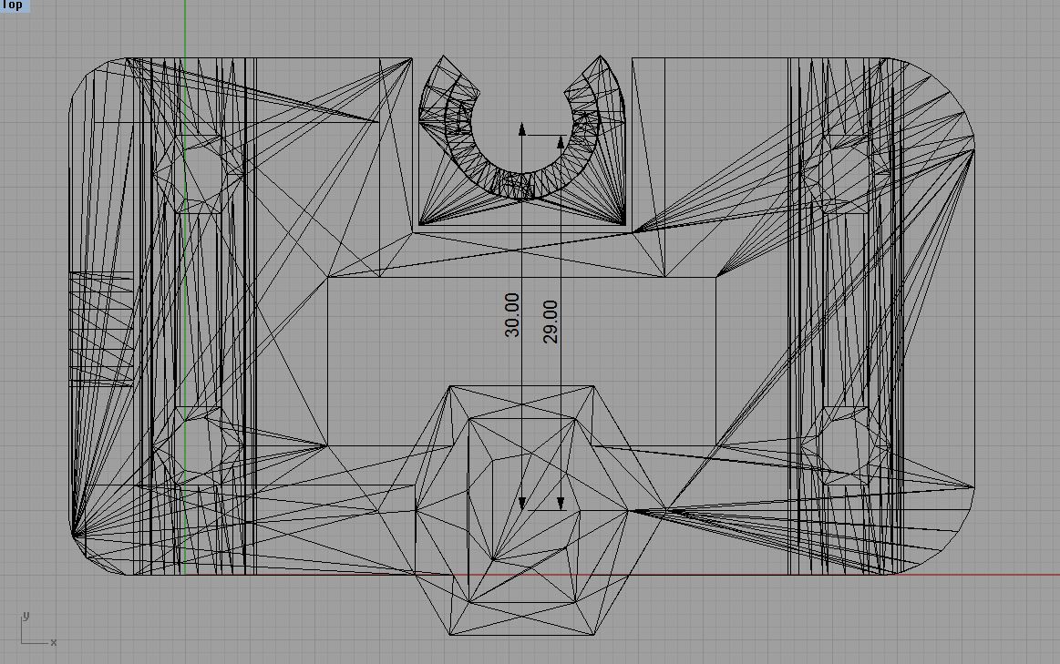
I wouldn't go for that though, but for the distance measured in the plans, or in default, slicings & projections of stls.: 30 mm
Edit:: also have a look at objects like this one:
[www.thingiverse.com]
from the very first lines of the openscad file:
...
As a minimum, you must have the same spacings between the Z smooth rod and the Z screw rod
* on the top Z motor brackets
* and on the x-ends.
(I have found that with standard prusa mendel files it is not possible to get those two distance exactly equal because the Z motor mount does not allow for sufficient lateral adustment. Other peiople have posted similar results)
The lack of a standard reference has convinced me of the need to check _any_ downloaded files for key dimensions.
Or to draw my own pieces: too much confusion
Edited 1 time(s). Last edit at 09/01/2011 03:03PM by Lanthan.
I wouldn't go for that though, but for the distance measured in the plans, or in default, slicings & projections of stls.: 30 mm
Edit:: also have a look at objects like this one:
[www.thingiverse.com]
from the very first lines of the openscad file:
// PRUSA Mendel
// GNU GPL v2
// Z threaded rod constraint

include

outer_diameter = m8_diameter/2+3.3;
shaft_separation = 30;
bearing_od = 22.6;
bearing_id = m8_diameter;
bearing_rodhole_d = bearing_id + 3;
...
As a minimum, you must have the same spacings between the Z smooth rod and the Z screw rod
* on the top Z motor brackets
* and on the x-ends.
(I have found that with standard prusa mendel files it is not possible to get those two distance exactly equal because the Z motor mount does not allow for sufficient lateral adustment. Other peiople have posted similar results)
The lack of a standard reference has convinced me of the need to check _any_ downloaded files for key dimensions.
Or to draw my own pieces: too much confusion
Edited 1 time(s). Last edit at 09/01/2011 03:03PM by Lanthan.
|
Re: Vertical X-axis standard September 01, 2011 05:57PM |
Registered: 13 years ago Posts: 632 |
OK, so in hopes of getting decision-by-committee finalized in some reasonable time frame (is that possible?, I'll declare the sense of the discussion to be that a good standard would be 70 mm x smooth rod center to center and 30 mm z smooth to threaded rod center to center. This should ensure that any vertical x axis assembly/x carriage design will play at least sorta nice with other conforming bots. Hows about we take that as a preliminary standard, allow a week for further comment, and try to call it final if there's no change in the consensus of the discussion by then.
P.S. Since RepRap "doesn't do" official, none of this really matters unless the various concerned parties actually adopt the standard and people start to use these types of parts interchangeably. So in the end we will have an unofficial nonbinding standard that you can follow or not at your whim. Won't that be cool?
, I'll declare the sense of the discussion to be that a good standard would be 70 mm x smooth rod center to center and 30 mm z smooth to threaded rod center to center. This should ensure that any vertical x axis assembly/x carriage design will play at least sorta nice with other conforming bots. Hows about we take that as a preliminary standard, allow a week for further comment, and try to call it final if there's no change in the consensus of the discussion by then. P.S. Since RepRap "doesn't do" official, none of this really matters unless the various concerned parties actually adopt the standard and people start to use these types of parts interchangeably. So in the end we will have an unofficial nonbinding standard that you can follow or not at your whim. Won't that be cool?
|
Re: Vertical X-axis standard September 01, 2011 06:01PM |
Registered: 13 years ago Posts: 601 |

|
Re: Vertical X-axis standard September 01, 2011 06:11PM |
Registered: 13 years ago Posts: 228 |
Yep. 
But above all, publish it, publish it and publish it. Make noise. Make a wiki page. Scream, squeal, organize contests, jousts, pageants, whatever: Get the ppl's attention on those so-boring but fundamental decisions about "standards".
Edited 1 time(s). Last edit at 09/01/2011 06:12PM by Lanthan.
But above all, publish it, publish it and publish it. Make noise. Make a wiki page. Scream, squeal, organize contests, jousts, pageants, whatever: Get the ppl's attention on those so-boring but fundamental decisions about "standards".
Edited 1 time(s). Last edit at 09/01/2011 06:12PM by Lanthan.
|
Re: Vertical X-axis standard September 01, 2011 07:54PM |
Registered: 13 years ago Posts: 632 |
I'm tempted to organize a contest myself, especially after I waxed eloquent a few months back about how to do it right. See post here [forums.reprap.org]. I'll give it some thought. As for the proper page for it, I think there is a reprap wiki page on standards. I don't know if there are any actual proposed standards in it yet or not. As for promotion, if I decide to do a contest, you'll see promotion, I can guarantee you that.
See post here [forums.reprap.org]. I'll give it some thought. As for the proper page for it, I think there is a reprap wiki page on standards. I don't know if there are any actual proposed standards in it yet or not. As for promotion, if I decide to do a contest, you'll see promotion, I can guarantee you that.
|
Re: Vertical X-axis standard September 03, 2011 05:47AM |
Registered: 13 years ago Posts: 615 |
|
Re: Vertical X-axis standard September 03, 2011 06:28AM |
Registered: 13 years ago Posts: 615 |

|
Re: Vertical X-axis standard September 03, 2011 04:03PM |
Registered: 13 years ago Posts: 632 |
|
Re: Vertical X-axis standard September 07, 2011 01:10PM |
Registered: 13 years ago Posts: 632 |
|
Re: Vertical X-axis standard September 09, 2011 03:22AM |
Registered: 13 years ago Posts: 615 |
|
Re: Vertical X-axis standard September 10, 2011 09:40PM |
Registered: 13 years ago Posts: 632 |
Created a wiki page here [reprap.org]. Please update it with your project if you intend to adopt the standard, or just post a quick "count me in" here and I'll put your project in the Standards Compliant Projects section.
|
Re: Vertical X-axis standard September 12, 2011 12:05PM |
Registered: 13 years ago Posts: 632 |
So I went and stuck my foot in it. I have organized a contest to encourage designers to tweak existing projects and/or design new parts to the new [reprap.org] vertical X axis standard. The contest page is here [reprap.org] . Those wishing to participate must declare their intent by Oct 12. The contest will run to Nov 12 if enough entrants declare by Oct 12. Any and all publicity/blog posts etc. would be appreciated.
|
Re: Vertical X-axis standard September 12, 2011 12:33PM |
Admin Registered: 17 years ago Posts: 7,879 |
What is the reason for moving to a vertical axis? Horizontal splits the weight between the two rods, vertical doesn't so you will get more sag.
[www.hydraraptor.blogspot.com]
[www.hydraraptor.blogspot.com]
|
Re: Vertical X-axis standard September 12, 2011 12:40PM |
Registered: 13 years ago Posts: 632 |
hopefully, better stiffness around the x axis, smaller parts/shorter printing time, easier tool changes, integrated carriage-extruder designs to name a few. Seems like the vertical X axis could still distribute the weight to both smooth rod too. Don't see why it couldn't unless the bearings/bushings were spaced wrong.

Sorry, only registered users may post in this forum.