Τεχνικά προβλήματα
Posted by IronG
|
Τεχνικά προβλήματα June 05, 2014 12:11PM |
Registered: 9 years ago Posts: 17 |
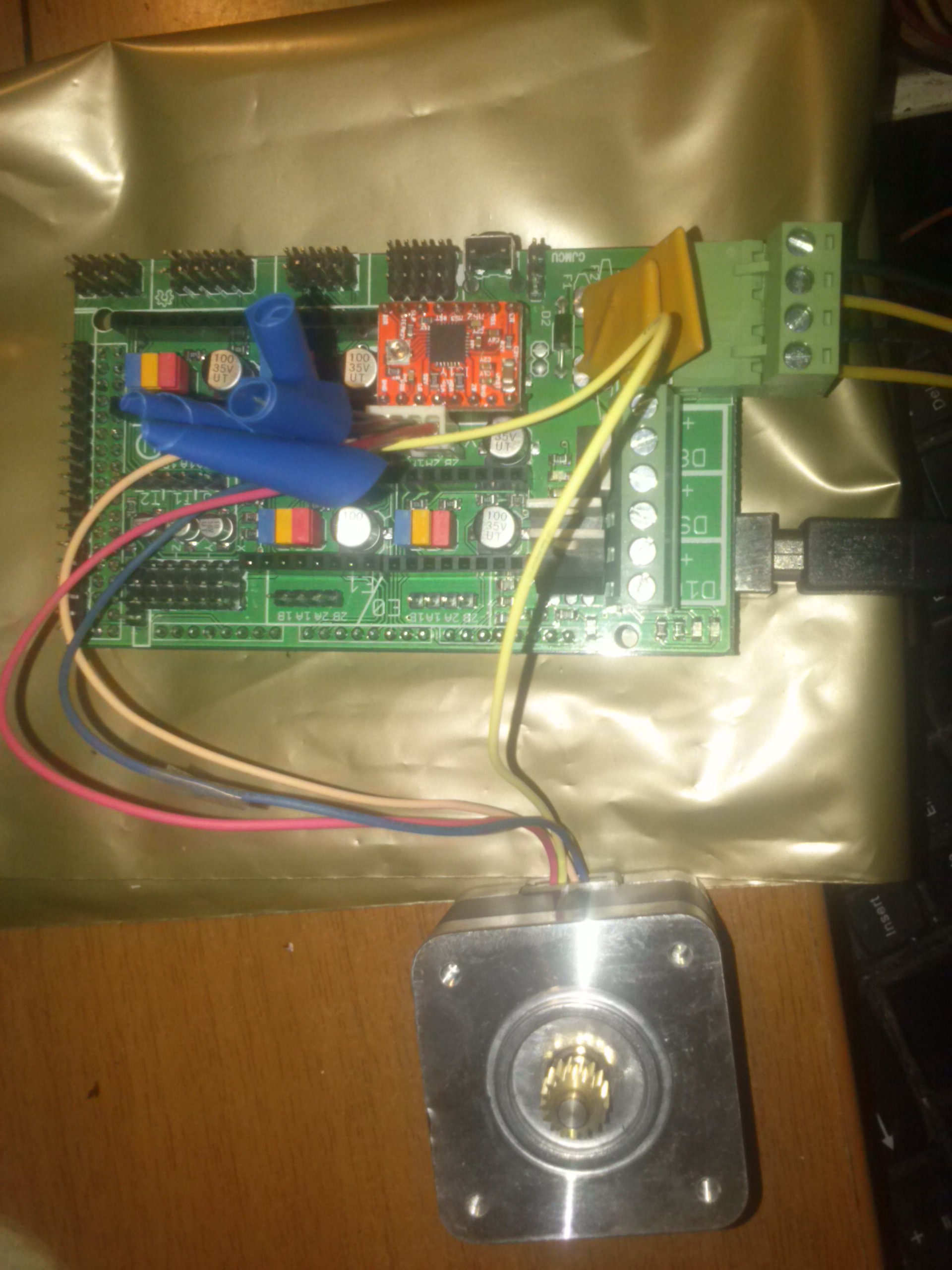
Γεια σας και από μένα, είμαι καινούργιος στο 3d printing και προσπαθώ να φτιάξω τον δικό μου diy εκτυπωτή. Έχω αγοράσει κάποια εξαρτήματα και προσπαθώ να κάνω μια δοκιμή στα ηλεκτρονικά κομμάτια για να διαπιστώσω αν δουλεύουν αλλά έχω χάσει τη μπάλα με τα firmware και τα προγράμματα. Μπορεί κάποιος να βοηθήσει βήμα προς βήμα μέχρι να βγάλω άκρη ; Έφαγα όλο το διαδίκτυο και άκρη δε βρήκα, επισυνάπτω μια φωτογραφία. Κάθε βοήθεια ευπρόσδεκτη.
|
Re: Τεχνικά προβλήματα June 11, 2014 05:19PM |
Registered: 11 years ago Posts: 37 |
Για αρχή πρέπει να φορτώσεις κάποιο firmware στο Arduino σου αν αυτό δεν έχει γίνει ήδη. Θα πρότεινα Marlin: [github.com]
Οδηγίες για το πώς, θα βρείς στην ίδια σελίδα.
Έπειτα θα χρειαστείς κάποιο host software για να "μιλήσει" το pc σου με το RAMPS. Printrun, Repetier Host και ReplicatorG είναι κάποιες από τις free λύσεις. Αν θες πες μας λίγα παραπάνω για τον εξοπλισμό που έχεις αγοράσει για να μπορούμε να σε βοηθήσουμε καλύτερα.
|
Re: Τεχνικά προβλήματα June 12, 2014 08:07PM |
Registered: 9 years ago Posts: 17 |
|
Re: Τεχνικά προβλήματα September 11, 2014 01:52AM |
Registered: 9 years ago Posts: 19 |
Απορίες αρχάριου επί του θέματος. ΣΗΜΕΊΩΣΗ: πρώτη φορά πιάνω Arduino στα χέρια μου.
Έχω ένα (κινέζο)Arduino MEGA 2560, αν κατάλαβα σωστά τα βήματα πάνε ως εξής:
1)Κατεβάζω το IDE του Arduino και φορτώνω το Marlin.pde μέσω του καλωδίου του.
Χρειάζεται πιο πριν να φορτώσω κάτι στο Ardiuno; Το έχω ακόμη στη συσκευασία που ήρθε.
2)Μετά 'κουμπώνω' πάνω το Ramps 1.4 με τους Stepper drivers Α4988, βάζω τα καλώδια εκεί που πρέπει και μετά;
Έχω πάρει και ένα Controller Display (bit.ly/1qHYMbb), το συνδέω και αυτό μαζί ή όχι;
3)Συνδέω τα πάντα με τον υπολογιστή μου και ανοίγω το Repetier (ή ότι άλλο καταφέρω να δουλέψει στο openSUSE) και αρχίζω να παίζω.
Τα κατάλαβα σωστά ή κάτι μου φεύγει;
Φτιάχνω ένα Prusa i3 οπότε οποιαδήποτε άλλη συμβουλή-ρύθμιση είναι παραπάνω από καλοδεχούμενη.
|
Re: Τεχνικά προβλήματα September 11, 2014 02:49AM |
Registered: 11 years ago Posts: 37 |
|
Re: Τεχνικά προβλήματα September 11, 2014 03:49AM |
Registered: 9 years ago Posts: 19 |

|
Re: Τεχνικά προβλήματα September 11, 2014 04:56AM |
Registered: 11 years ago Posts: 37 |
Ρίξε μια ματια σε αυτό:
[gadgets3d.com]
και σε αυτό:
[www.nextdayreprap.co.uk]
Σχετικά με το configuration του Marlin δεν μπορώ να απαντήσω γιατί δεν ξέρω τι εξαρτήματα έχεις
Ο καλύτερος σου φίλος , αν δεν είναι είδη, θα γίνει το Google μιας και καταπιάστηκες με τέτοια
[gadgets3d.com]
και σε αυτό:
[www.nextdayreprap.co.uk]
Σχετικά με το configuration του Marlin δεν μπορώ να απαντήσω γιατί δεν ξέρω τι εξαρτήματα έχεις
Ο καλύτερος σου φίλος , αν δεν είναι είδη, θα γίνει το Google μιας και καταπιάστηκες με τέτοια
|
Re: Τεχνικά προβλήματα September 26, 2014 03:53AM |
Registered: 9 years ago Posts: 19 |
Λοιπόοοοον
όπως είπα έχω ένα Arduino Mega 2560 οπότε για να το κάνω λίγο πιο αναλυτικό...
-Ανοίγω το Arduino IDE (στην προκειμένη περίπτωση την έκδοση 1.0.5 που μου δίνει το openSUSE 13.1)
-Επιλέγω πλακέτα στο IDE
-Ανοίγω το Marlin.pde
-Κάνω τις ρυθμίσεις σύμφωνα με το Hardware μου
-Φορτώνω τις ρυθμίσεις στην πλακέτα
-Κουμπώνω το Ramps 1.4 με τους steppers και συνδέω τα καλώδια
-Συνδέω τα πάντα με το τροφοδοτικό
-Συνδέω με τον υπολογιστή
-Ανοίγω το π.χ Repetier
-Καλυμπράρω και τυπώνω
Σωστά;
Να με συγχωρείτε αν γίνομε κουραστικός αλλά φοβάμαι μην κάψω καμιά πλακέτα και περιμένω πάλι κάνα μήνα.
Τα καλά νέα είναι ότι δοκίμασα το τροφοδοτικό (χωρίς τίποτα πάνω) και δείχνει ότι δουλεύει, οι ιμάντες μου δείχνουν καλά τεντωμένοι, το κρεβάτι δείχνει πολύ καλά ισορροπημένο και τελείωσα και με τον Extruder
Τις επόμενες μέρες θα συμμαζεύω καλώδια για να μην πετάνε από εδώ και από εκεί και θα βάλω τα endstops(Αφού βρω χρόνο να πάω στον Ανέστη να μου τυπώσει την μια βάση που μου λείπει)
Ευχαριστώ εκ των προτέρων. Να περνάτε καλά.
Κώστας
|
Re: Τεχνικά προβλήματα September 27, 2014 10:05AM |
Registered: 11 years ago Posts: 37 |
|
Re: Τεχνικά προβλήματα April 06, 2015 09:02AM |
Registered: 9 years ago Posts: 17 |
Γειά σας
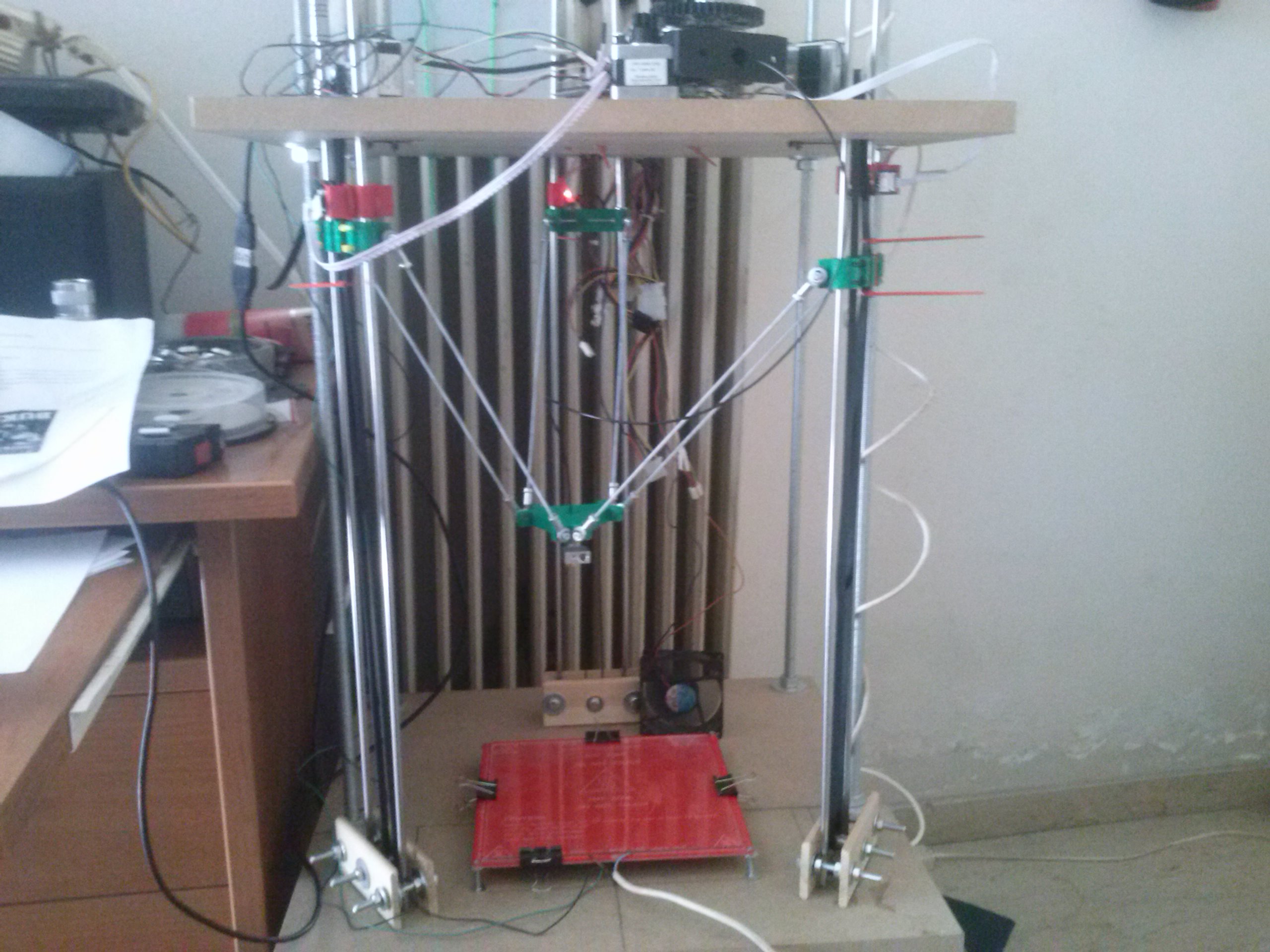
Ολοκλήρωσα μια κατασκευή ενός εκτυπωτή delta και χρειάζομαι οδηγίες για να προχωρήσω σε εκτύπωση.
Το firmware που χρησιμοποιώ είναι το Marlin και το πρόγραμμα το Repetier, αλλά μάλλον δε κάνω κάτι σωστά στις ρυθμίσεις και η εκτυπωση δε ξεκινάει.
Τι μπορεί να κάνω λάθος; Ευπρόσδεκτη οποιαδήποτε βοήθεια.
|
Re: Τεχνικά προβλήματα April 21, 2015 06:09AM |
Registered: 12 years ago Posts: 25 |
Quote
IronG
Γειά σας
Ολοκλήρωσα μια κατασκευή ενός εκτυπωτή delta και χρειάζομαι οδηγίες για να προχωρήσω σε εκτύπωση.
Το firmware που χρησιμοποιώ είναι το Marlin και το πρόγραμμα το Repetier, αλλά μάλλον δε κάνω κάτι σωστά στις ρυθμίσεις και η εκτυπωση δε ξεκινάει.
Τι μπορεί να κάνω λάθος; Ευπρόσδεκτη οποιαδήποτε βοήθεια.
Τι κάνει δηλαδή το μηχάνημα? τίποτα?
Όταν δίνεις κίνηση στους άξονες μέσω του πάνελ κινείται?
|
Re: Τεχνικά προβλήματα April 26, 2015 05:51AM |
Registered: 9 years ago Posts: 17 |
|
Re: Τεχνικά προβλήματα April 26, 2015 08:18AM |
Registered: 9 years ago Posts: 17 |
|
Re: Τεχνικά προβλήματα April 27, 2015 02:55PM |
Registered: 9 years ago Posts: 17 |
Για να γίνω ποιο σαφής, το πρόβλημά μου είναι οτι όταν κάνω homing από την επιλογή του Repetier, τα endstops δεν λειτουργούν. Παραθέτω το configuration.h από το firmware
#ifndef CONFIGURATION_H
#define CONFIGURATION_H
// This configuration file contains the basic settings.
// Advanced settings can be found in Configuration_adv.h
// BASIC SETTINGS: select your board type, temperature sensor type, axis scaling, and endstop configuration
//===========================================================================
//============================= DELTA Printer ===============================
//===========================================================================
// For a Delta printer rplace the configuration files wilth the files in the
// example_configurations/delta directory.
//
// User-specified version info of this build to display in [Pronterface, etc] terminal window during
// startup. Implementation of an idea by Prof Braino to inform user that any changes made to this
// build by the user have been successfully uploaded into firmware.
#define STRING_VERSION_CONFIG_H __DATE__ " " __TIME__ // build date and time
#define STRING_CONFIG_H_AUTHOR "(none, default config)" // Who made the changes.
// SERIAL_PORT selects which serial port should be used for communication with the host.
// This allows the connection of wireless adapters (for instance) to non-default port pins.
// Serial port 0 is still used by the Arduino bootloader regardless of this setting.
#define SERIAL_PORT 0
// This determines the communication speed of the printer
#define BAUDRATE 115200
// This enables the serial port associated to the Bluetooth interface
//#define BTENABLED // Enable BT interface on AT90USB devices
//// The following define selects which electronics board you have. Please choose the one that matches your setup
// 10 = Gen7 custom (Alfons3 Version) "https://github.com/Alfons3/Generation_7_Electronics"
// 11 = Gen7 v1.1, v1.2 = 11
// 12 = Gen7 v1.3
// 13 = Gen7 v1.4
// 2 = Cheaptronic v1.0
// 20 = Sethi 3D_1
// 3 = MEGA/RAMPS up to 1.2 = 3
// 33 = RAMPS 1.3 / 1.4 (Power outputs: Extruder, Fan, Bed)
// 34 = RAMPS 1.3 / 1.4 (Power outputs: Extruder0, Extruder1, Bed)
// 35 = RAMPS 1.3 / 1.4 (Power outputs: Extruder, Fan, Fan)
// 4 = Duemilanove w/ ATMega328P pin assignment
// 5 = Gen6
// 51 = Gen6 deluxe
// 6 = Sanguinololu < 1.2
// 62 = Sanguinololu 1.2 and above
// 63 = Melzi
// 64 = STB V1.1
// 65 = Azteeg X1
// 66 = Melzi with ATmega1284 (MaKr3d version)
// 67 = Azteeg X3
// 7 = Ultimaker
// 71 = Ultimaker (Older electronics. Pre 1.5.4. This is rare)
// 77 = 3Drag Controller
// 8 = Teensylu
// 80 = Rumba
// 81 = Printrboard (AT90USB1286)
// 82 = Brainwave (AT90USB646)
// 83 = SAV Mk-I (AT90USB1286)
// 9 = Gen3+
// 70 = Megatronics
// 701= Megatronics v2.0
// 702= Minitronics v1.0
// 90 = Alpha OMCA board
// 91 = Final OMCA board
// 301 = Rambo
// 21 = Elefu Ra Board (v3)
#ifndef MOTHERBOARD
#define MOTHERBOARD 33
#endif
// Define this to set a custom name for your generic Mendel,
// #define CUSTOM_MENDEL_NAME "This Mendel"
// Define this to set a unique identifier for this printer, (Used by some programs to differentiate between machines)
// You can use an online service to generate a random UUID. (eg [www.uuidgenerator.net])
// #define MACHINE_UUID "00000000-0000-0000-0000-000000000000"
// This defines the number of extruders
#define EXTRUDERS 1
//// The following define selects which power supply you have. Please choose the one that matches your setup
// 1 = ATX
// 2 = X-Box 360 203Watts (the blue wire connected to PS_ON and the red wire to VCC)
#define POWER_SUPPLY 1
// Define this to have the electronics keep the powersupply off on startup. If you don't know what this is leave it.
// #define PS_DEFAULT_OFF
//===========================================================================
//============================== Delta Settings =============================
//===========================================================================
// Enable DELTA kinematics and most of the default configuration for Deltas
#define DELTA
// Make delta curves from many straight lines (linear interpolation).
// This is a trade-off between visible corners (not enough segments)
// and processor overload (too many expensive sqrt calls).
#define DELTA_SEGMENTS_PER_SECOND 200
// NOTE NB all values for DELTA_* values MOUST be floating point, so always have a decimal point in them
// Center-to-center distance of the holes in the diagonal push rods.
#define DELTA_DIAGONAL_ROD 275.0 // mm
// Horizontal offset from middle of printer to smooth rod center.
#define DELTA_SMOOTH_ROD_OFFSET 200.0 // mm
// Horizontal offset of the universal joints on the end effector.
#define DELTA_EFFECTOR_OFFSET 15.0 // mm
// Horizontal offset of the universal joints on the carriages.
#define DELTA_CARRIAGE_OFFSET 25.0 // mm
// Effective horizontal distance bridged by diagonal push rods.
#define DELTA_RADIUS (DELTA_SMOOTH_ROD_OFFSET-DELTA_EFFECTOR_OFFSET-DELTA_CARRIAGE_OFFSET)
#define DELTA_DIAGONAL_ROD_2 sq(DELTA_DIAGONAL_ROD)
// Effective X/Y positions of the three vertical towers.
#define SIN_60 0.8660254037844386
#define COS_60 0.5
#define DELTA_TOWER1_X -SIN_60*DELTA_RADIUS // front left tower
#define DELTA_TOWER1_Y -COS_60*DELTA_RADIUS
#define DELTA_TOWER2_X SIN_60*DELTA_RADIUS // front right tower
#define DELTA_TOWER2_Y -COS_60*DELTA_RADIUS
#define DELTA_TOWER3_X 0.0 // back middle tower
#define DELTA_TOWER3_Y DELTA_RADIUS
//===========================================================================
//=============================Thermal Settings ============================
//===========================================================================
//
//--NORMAL IS 4.7kohm PULLUP!-- 1kohm pullup can be used on hotend sensor, using correct resistor and table
//
//// Temperature sensor settings:
// -2 is thermocouple with MAX6675 (only for sensor 0)
// -1 is thermocouple with AD595
// 0 is not used
// 1 is 100k thermistor - best choice for EPCOS 100k (4.7k pullup)
// 2 is 200k thermistor - ATC Semitec 204GT-2 (4.7k pullup)
// 3 is mendel-parts thermistor (4.7k pullup)
// 4 is 10k thermistor !! do not use it for a hotend. It gives bad resolution at high temp. !!
// 5 is 100K thermistor - ATC Semitec 104GT-2 (Used in ParCan & J-Head) (4.7k pullup)
// 6 is 100k EPCOS - Not as accurate as table 1 (created using a fluke thermocouple) (4.7k pullup)
// 7 is 100k Honeywell thermistor 135-104LAG-J01 (4.7k pullup)
// 71 is 100k Honeywell thermistor 135-104LAF-J01 (4.7k pullup)
// 8 is 100k 0603 SMD Vishay NTCS0603E3104FXT (4.7k pullup)
// 9 is 100k GE Sensing AL03006-58.2K-97-G1 (4.7k pullup)
// 10 is 100k RS thermistor 198-961 (4.7k pullup)
// 60 is 100k Maker's Tool Works Kapton Bed Thermister
//
// 1k ohm pullup tables - This is not normal, you would have to have changed out your 4.7k for 1k
// (but gives greater accuracy and more stable PID)
// 51 is 100k thermistor - EPCOS (1k pullup)
// 52 is 200k thermistor - ATC Semitec 204GT-2 (1k pullup)
// 55 is 100k thermistor - ATC Semitec 104GT-2 (Used in ParCan & J-Head) (1k pullup)
#define TEMP_SENSOR_0 8
#define TEMP_SENSOR_1 0
#define TEMP_SENSOR_2 0
#define TEMP_SENSOR_BED 8
// This makes temp sensor 1 a redundant sensor for sensor 0. If the temperatures difference between these sensors is to high the print will be aborted.
//#define TEMP_SENSOR_1_AS_REDUNDANT
#define MAX_REDUNDANT_TEMP_SENSOR_DIFF 10
// Actual temperature must be close to target for this long before M109 returns success
#define TEMP_RESIDENCY_TIME 10 // (seconds)
#define TEMP_HYSTERESIS 3 // (degC) range of +/- temperatures considered "close" to the target one
#define TEMP_WINDOW 1 // (degC) Window around target to start the residency timer x degC early.
// The minimal temperature defines the temperature below which the heater will not be enabled It is used
// to check that the wiring to the thermistor is not broken.
// Otherwise this would lead to the heater being powered on all the time.
#define HEATER_0_MINTEMP 5
#define HEATER_1_MINTEMP 5
#define HEATER_2_MINTEMP 5
#define BED_MINTEMP 5
// When temperature exceeds max temp, your heater will be switched off.
// This feature exists to protect your hotend from overheating accidentally, but *NOT* from thermistor short/failure!
// You should use MINTEMP for thermistor short/failure protection.
#define HEATER_0_MAXTEMP 230
#define HEATER_1_MAXTEMP 230
#define HEATER_2_MAXTEMP 230
#define BED_MAXTEMP 120
// If your bed has low resistance e.g. .6 ohm and throws the fuse you can duty cycle it to reduce the
// average current. The value should be an integer and the heat bed will be turned on for 1 interval of
// HEATER_BED_DUTY_CYCLE_DIVIDER intervals.
//#define HEATER_BED_DUTY_CYCLE_DIVIDER 4
// PID settings:
// Comment the following line to disable PID and enable bang-bang.
#define PIDTEMP
#define BANG_MAX 255 // limits current to nozzle while in bang-bang mode; 255=full current
#define PID_MAX 255 // limits current to nozzle while PID is active (see PID_FUNCTIONAL_RANGE below); 255=full current
#ifdef PIDTEMP
//#define PID_DEBUG // Sends debug data to the serial port.
//#define PID_OPENLOOP 1 // Puts PID in open loop. M104/M140 sets the output power from 0 to PID_MAX
#define PID_FUNCTIONAL_RANGE 10 // If the temperature difference between the target temperature and the actual temperature
// is more then PID_FUNCTIONAL_RANGE then the PID will be shut off and the heater will be set to min/max.
#define PID_INTEGRAL_DRIVE_MAX 255 //limit for the integral term
#define K1 0.95 //smoothing factor within the PID
#define PID_dT ((16.0 * 8.0)/(F_CPU / 64.0 / 256.0)) //sampling period of the temperature routine
// If you are using a preconfigured hotend then you can use one of the value sets by uncommenting it
// Ultimaker
#define DEFAULT_Kp 22.2
#define DEFAULT_Ki 1.08
#define DEFAULT_Kd 114
// Makergear
// #define DEFAULT_Kp 7.0
// #define DEFAULT_Ki 0.1
// #define DEFAULT_Kd 12
// Mendel Parts V9 on 12V
// #define DEFAULT_Kp 63.0
// #define DEFAULT_Ki 2.25
// #define DEFAULT_Kd 440
#endif // PIDTEMP
// Bed Temperature Control
// Select PID or bang-bang with PIDTEMPBED. If bang-bang, BED_LIMIT_SWITCHING will enable hysteresis
//
// Uncomment this to enable PID on the bed. It uses the same frequency PWM as the extruder.
// If your PID_dT above is the default, and correct for your hardware/configuration, that means 7.689Hz,
// which is fine for driving a square wave into a resistive load and does not significantly impact you FET heating.
// This also works fine on a Fotek SSR-10DA Solid State Relay into a 250W heater.
// If your configuration is significantly different than this and you don't understand the issues involved, you probably
// shouldn't use bed PID until someone else verifies your hardware works.
// If this is enabled, find your own PID constants below.
//#define PIDTEMPBED
//
//#define BED_LIMIT_SWITCHING
// This sets the max power delivered to the bed, and replaces the HEATER_BED_DUTY_CYCLE_DIVIDER option.
// all forms of bed control obey this (PID, bang-bang, bang-bang with hysteresis)
// setting this to anything other than 255 enables a form of PWM to the bed just like HEATER_BED_DUTY_CYCLE_DIVIDER did,
// so you shouldn't use it unless you are OK with PWM on your bed. (see the comment on enabling PIDTEMPBED)
#define MAX_BED_POWER 255 // limits duty cycle to bed; 255=full current
#ifdef PIDTEMPBED
//120v 250W silicone heater into 4mm borosilicate (MendelMax 1.5+)
//from FOPDT model - kp=.39 Tp=405 Tdead=66, Tc set to 79.2, aggressive factor of .15 (vs .1, 1, 10)
#define DEFAULT_bedKp 10.00
#define DEFAULT_bedKi .023
#define DEFAULT_bedKd 305.4
//120v 250W silicone heater into 4mm borosilicate (MendelMax 1.5+)
//from pidautotune
// #define DEFAULT_bedKp 97.1
// #define DEFAULT_bedKi 1.41
// #define DEFAULT_bedKd 1675.16
// FIND YOUR OWN: "M303 E-1 C8 S90" to run autotune on the bed at 90 degreesC for 8 cycles.
#endif // PIDTEMPBED
//this prevents dangerous Extruder moves, i.e. if the temperature is under the limit
//can be software-disabled for whatever purposes by
#define PREVENT_DANGEROUS_EXTRUDE
//if PREVENT_DANGEROUS_EXTRUDE is on, you can still disable (uncomment) very long bits of extrusion separately.
#define PREVENT_LENGTHY_EXTRUDE
#define EXTRUDE_MINTEMP 170
#define EXTRUDE_MAXLENGTH (X_MAX_LENGTH+Y_MAX_LENGTH) //prevent extrusion of very large distances.
//===========================================================================
//=============================Mechanical Settings===========================
//===========================================================================
// Uncomment the following line to enable CoreXY kinematics
// #define COREXY
// coarse Endstop Settings
#define ENDSTOPPULLUPS // Comment this out (using // at the start of the line) to disable the endstop pullup resistors
#ifndef ENDSTOPPULLUPS
// fine Enstop settings: Individual Pullups. will be ignored if ENDSTOPPULLUPS is defined
// #define ENDSTOPPULLUP_XMAX
// #define ENDSTOPPULLUP_YMAX
// #define ENDSTOPPULLUP_ZMAX
// #define ENDSTOPPULLUP_XMIN
// #define ENDSTOPPULLUP_YMIN
// #define ENDSTOPPULLUP_ZMIN
#endif
#ifdef ENDSTOPPULLUPS
#define ENDSTOPPULLUP_XMAX
#define ENDSTOPPULLUP_YMAX
#define ENDSTOPPULLUP_ZMAX
#define ENDSTOPPULLUP_XMIN
#define ENDSTOPPULLUP_YMIN
#define ENDSTOPPULLUP_ZMIN
#endif
// The pullups are needed if you directly connect a mechanical endswitch between the signal and ground pins.
const bool X_MIN_ENDSTOP_INVERTING = true; // set to true to invert the logic of the endstop.
const bool Y_MIN_ENDSTOP_INVERTING = true; // set to true to invert the logic of the endstop.
const bool Z_MIN_ENDSTOP_INVERTING = true; // set to true to invert the logic of the endstop.
const bool X_MAX_ENDSTOP_INVERTING = true; // set to true to invert the logic of the endstop.
const bool Y_MAX_ENDSTOP_INVERTING = true; // set to true to invert the logic of the endstop.
const bool Z_MAX_ENDSTOP_INVERTING = true; // set to true to invert the logic of the endstop.
//#define DISABLE_MAX_ENDSTOPS
// Deltas never have min endstops
#define DISABLE_MIN_ENDSTOPS
// Disable max endstops for compatibility with endstop checking routine
#if defined(COREXY) && !defined(DISABLE_MAX_ENDSTOPS)
#define DISABLE_MAX_ENDSTOPS
#endif
// For Inverting Stepper Enable Pins (Active Low) use 0, Non Inverting (Active High) use 1
#define X_ENABLE_ON 0
#define Y_ENABLE_ON 0
#define Z_ENABLE_ON 0
#define E_ENABLE_ON 0 // For all extruders
// Disables axis when it's not being used.
#define DISABLE_X false
#define DISABLE_Y false
#define DISABLE_Z false
#define DISABLE_E false // For all extruders
#define INVERT_X_DIR false // DELTA does not invert
#define INVERT_Y_DIR false
#define INVERT_Z_DIR false
#define INVERT_E0_DIR false // for direct drive extruder v9 set to true, for geared extruder set to false
#define INVERT_E1_DIR false // for direct drive extruder v9 set to true, for geared extruder set to false
#define INVERT_E2_DIR false // for direct drive extruder v9 set to true, for geared extruder set to false
// ENDSTOP SETTINGS:
// Sets direction of endstops when homing; 1=MAX, -1=MIN
// deltas always home to max
#define X_HOME_DIR 1
#define Y_HOME_DIR 1
#define Z_HOME_DIR 1
#define min_software_endstops true // If true, axis won't move to coordinates less than HOME_POS.
#define max_software_endstops true // If true, axis won't move to coordinates greater than the defined lengths below.
// Travel limits after homing
#define X_MAX_POS 90
#define X_MIN_POS -90
#define Y_MAX_POS 90
#define Y_MIN_POS -90
#define Z_MAX_POS MANUAL_Z_HOME_POS
#define Z_MIN_POS 0
#define X_MAX_LENGTH (X_MAX_POS - X_MIN_POS)
#define Y_MAX_LENGTH (Y_MAX_POS - Y_MIN_POS)
#define Z_MAX_LENGTH (Z_MAX_POS - Z_MIN_POS)
//============================= Bed Auto Leveling ===========================
//#define ENABLE_AUTO_BED_LEVELING // Delete the comment to enable (remove // at the start of the line)
#ifdef ENABLE_AUTO_BED_LEVELING
// these are the positions on the bed to do the probing
#define LEFT_PROBE_BED_POSITION 15
#define RIGHT_PROBE_BED_POSITION 170
#define BACK_PROBE_BED_POSITION 180
#define FRONT_PROBE_BED_POSITION 20
// these are the offsets to the prob relative to the extruder tip (Hotend - Probe)
#define X_PROBE_OFFSET_FROM_EXTRUDER -25
#define Y_PROBE_OFFSET_FROM_EXTRUDER -29
#define Z_PROBE_OFFSET_FROM_EXTRUDER -12.35
#define Z_RAISE_BEFORE_HOMING 4 // (in mm) Raise Z before homing (G28) for Probe Clearance.
// Be sure you have this distance over your Z_MAX_POS in case
#define XY_TRAVEL_SPEED 8000 // X and Y axis travel speed between probes, in mm/min
#define Z_RAISE_BEFORE_PROBING 15 //How much the extruder will be raised before traveling to the first probing point.
#define Z_RAISE_BETWEEN_PROBINGS 5 //How much the extruder will be raised when traveling from between next probing points
//If defined, the Probe servo will be turned on only during movement and then turned off to avoid jerk
//The value is the delay to turn the servo off after powered on - depends on the servo speed; 300ms is good value, but you can try lower it.
// You MUST HAVE the SERVO_ENDSTOPS defined to use here a value higher than zero otherwise your code will not compile.
// #define PROBE_SERVO_DEACTIVATION_DELAY 300
//If you have enabled the Bed Auto Levelling and are using the same Z Probe for Z Homing,
//it is highly recommended you let this Z_SAFE_HOMING enabled!!!
#define Z_SAFE_HOMING // This feature is meant to avoid Z homing with probe outside the bed area.
// When defined, it will:
// - Allow Z homing only after X and Y homing AND stepper drivers still enabled
// - If stepper drivers timeout, it will need X and Y homing again before Z homing
// - Position the probe in a defined XY point before Z Homing when homing all axis (G28)
// - Block Z homing only when the probe is outside bed area.
#ifdef Z_SAFE_HOMING
#define Z_SAFE_HOMING_X_POINT (X_MAX_LENGTH/2) // X point for Z homing when homing all axis (G28)
#define Z_SAFE_HOMING_Y_POINT (Y_MAX_LENGTH/2) // Y point for Z homing when homing all axis (G28)
#endif
#endif
// The position of the homing switches
//#define MANUAL_HOME_POSITIONS // If defined, MANUAL_*_HOME_POS below will be used
//#define BED_CENTER_AT_0_0 // If defined, the center of the bed is at (X=0, Y=0)
//Manual homing switch locations:
#define MANUAL_HOME_POSITIONS // MANUAL_*_HOME_POS below will be used
// For deltabots this means top and center of the cartesian print volume.
#define MANUAL_X_HOME_POS 0
#define MANUAL_Y_HOME_POS 0
#define MANUAL_Z_HOME_POS 250 // For delta: Distance between nozzle and print surface after homing.
//// MOVEMENT SETTINGS
#define NUM_AXIS 4 // The axis order in all axis related arrays is X, Y, Z, E
// delta homing speeds must be the same on xyz
#define HOMING_FEEDRATE {200*60, 200*60, 200*60, 0} // set the homing speeds (mm/min)
// default settings
// delta speeds must be the same on xyz
#define DEFAULT_AXIS_STEPS_PER_UNIT {80, 80, 80, 760*1.1} // default steps per unit for Kossel (GT2, 20 tooth)
#define DEFAULT_MAX_FEEDRATE {500, 500, 500, 25} // (mm/sec)
#define DEFAULT_MAX_ACCELERATION {9000,9000,9000,10000} // X, Y, Z, E maximum start speed for accelerated moves. E default values are good for skeinforge 40+, for older versions raise them a lot.
#define DEFAULT_ACCELERATION 3000 // X, Y, Z and E max acceleration in mm/s^2 for printing moves
#define DEFAULT_RETRACT_ACCELERATION 3000 // X, Y, Z and E max acceleration in mm/s^2 for retracts
// Offset of the extruders (uncomment if using more than one and relying on firmware to position when changing).
// The offset has to be X=0, Y=0 for the extruder 0 hotend (default extruder).
// For the other hotends it is their distance from the extruder 0 hotend.
// #define EXTRUDER_OFFSET_X {0.0, 20.00} // (in mm) for each extruder, offset of the hotend on the X axis
// #define EXTRUDER_OFFSET_Y {0.0, 5.00} // (in mm) for each extruder, offset of the hotend on the Y axis
// The speed change that does not require acceleration (i.e. the software might assume it can be done instantaneously)
#define DEFAULT_XYJERK 20.0 // (mm/sec)
#define DEFAULT_ZJERK 20.0 // (mm/sec) Must be same as XY for delta
#define DEFAULT_EJERK 5.0 // (mm/sec)
//===========================================================================
//=============================Additional Features===========================
//===========================================================================
// EEPROM
// the microcontroller can store settings in the EEPROM, e.g. max velocity...
// M500 - stores paramters in EEPROM
// M501 - reads parameters from EEPROM (if you need reset them after you changed them temporarily).
// M502 - reverts to the default "factory settings". You still need to store them in EEPROM afterwards if you want to.
//define this to enable eeprom support
//#define EEPROM_SETTINGS
//to disable EEPROM Serial responses and decrease program space by ~1700 byte: comment this out:
// please keep turned on if you can.
//#define EEPROM_CHITCHAT
// Preheat Constants
#define PLA_PREHEAT_HOTEND_TEMP 180
#define PLA_PREHEAT_HPB_TEMP 70
#define PLA_PREHEAT_FAN_SPEED 255 // Insert Value between 0 and 255
#define ABS_PREHEAT_HOTEND_TEMP 240
#define ABS_PREHEAT_HPB_TEMP 100
#define ABS_PREHEAT_FAN_SPEED 255 // Insert Value between 0 and 255
//LCD and SD support
//#define ULTRA_LCD //general lcd support, also 16x2
//#define DOGLCD // Support for SPI LCD 128x64 (Controller ST7565R graphic Display Family)
//#define SDSUPPORT // Enable SD Card Support in Hardware Console
//#define SDSLOW // Use slower SD transfer mode (not normally needed - uncomment if you're getting volume init error)
//#define ENCODER_PULSES_PER_STEP 1 // Increase if you have a high resolution encoder
//#define ENCODER_STEPS_PER_MENU_ITEM 5 // Set according to ENCODER_PULSES_PER_STEP or your liking
//#define ULTIMAKERCONTROLLER //as available from the ultimaker online store.
//#define ULTIPANEL //the ultipanel as on thingiverse
// The MaKr3d Makr-Panel with graphic controller and SD support
// [reprap.org]
//#define MAKRPANEL
// The RepRapDiscount Smart Controller (white PC
// [reprap.org]
//#define REPRAP_DISCOUNT_SMART_CONTROLLER
// The GADGETS3D G3D LCD/SD Controller (blue PC
// [reprap.org]
//#define G3D_PANEL
// The RepRapDiscount FULL GRAPHIC Smart Controller (quadratic white PC
// [reprap.org]
//
// ==> REMEMBER TO INSTALL U8glib to your ARDUINO library folder: [code.google.com]
//#define REPRAP_DISCOUNT_FULL_GRAPHIC_SMART_CONTROLLER
// The RepRapWorld REPRAPWORLD_KEYPAD v1.1
// [reprapworld.com]
//#define REPRAPWORLD_KEYPAD
//#define REPRAPWORLD_KEYPAD_MOVE_STEP 10.0 // how much should be moved when a key is pressed, eg 10.0 means 10mm per click
// The Elefu RA Board Control Panel
// [www.elefu.com]
// REMEMBER TO INSTALL LiquidCrystal_I2C.h in your ARUDINO library folder: [github.com]
//#define RA_CONTROL_PANEL
//automatic expansion
#if defined (MAKRPANEL)
#define DOGLCD
#define SDSUPPORT
#define ULTIPANEL
#define NEWPANEL
#define DEFAULT_LCD_CONTRAST 17
#endif
#if defined (REPRAP_DISCOUNT_FULL_GRAPHIC_SMART_CONTROLLER)
#define DOGLCD
#define U8GLIB_ST7920
#define REPRAP_DISCOUNT_SMART_CONTROLLER
#endif
#if defined(ULTIMAKERCONTROLLER) || defined(REPRAP_DISCOUNT_SMART_CONTROLLER) || defined(G3D_PANEL)
#define ULTIPANEL
#define NEWPANEL
#endif
#if defined(REPRAPWORLD_KEYPAD)
#define NEWPANEL
#define ULTIPANEL
#endif
#if defined(RA_CONTROL_PANEL)
#define ULTIPANEL
#define NEWPANEL
#define LCD_I2C_TYPE_PCA8574
#define LCD_I2C_ADDRESS 0x27 // I2C Address of the port expander
#endif
//I2C PANELS
//#define LCD_I2C_SAINSMART_YWROBOT
#ifdef LCD_I2C_SAINSMART_YWROBOT
// This uses the LiquidCrystal_I2C library ( [bitbucket.org] )
// Make sure it is placed in the Arduino libraries directory.
#define LCD_I2C_TYPE_PCF8575
#define LCD_I2C_ADDRESS 0x27 // I2C Address of the port expander
#define NEWPANEL
#define ULTIPANEL
#endif
// PANELOLU2 LCD with status LEDs, separate encoder and click inputs
//#define LCD_I2C_PANELOLU2
#ifdef LCD_I2C_PANELOLU2
// This uses the LiquidTWI2 library v1.2.3 or later ( [github.com] )
// Make sure the LiquidTWI2 directory is placed in the Arduino or Sketchbook libraries subdirectory.
// (v1.2.3 no longer requires you to define PANELOLU in the LiquidTWI2.h library header file)
// Note: The PANELOLU2 encoder click input can either be directly connected to a pin
// (if BTN_ENC defined to != -1) or read through I2C (when BTN_ENC == -1).
#define LCD_I2C_TYPE_MCP23017
#define LCD_I2C_ADDRESS 0x20 // I2C Address of the port expander
#define LCD_USE_I2C_BUZZER //comment out to disable buzzer on LCD
#define NEWPANEL
#define ULTIPANEL
#endif
// Panucatt VIKI LCD with status LEDs, integrated click & L/R/U/P buttons, separate encoder inputs
//#define LCD_I2C_VIKI
#ifdef LCD_I2C_VIKI
// This uses the LiquidTWI2 library v1.2.3 or later ( [github.com] )
// Make sure the LiquidTWI2 directory is placed in the Arduino or Sketchbook libraries subdirectory.
// Note: The pause/stop/resume LCD button pin should be connected to the Arduino
// BTN_ENC pin (or set BTN_ENC to -1 if not used)
#define LCD_I2C_TYPE_MCP23017
#define LCD_I2C_ADDRESS 0x20 // I2C Address of the port expander
#define LCD_USE_I2C_BUZZER //comment out to disable buzzer on LCD (requires LiquidTWI2 v1.2.3 or later)
#define NEWPANEL
#define ULTIPANEL
#endif
// Shift register panels
// ---------------------
// 2 wire Non-latching LCD SR from:
// [bitbucket.org]
//#define SR_LCD
#ifdef SR_LCD
#define SR_LCD_2W_NL // Non latching 2 wire shiftregister
//#define NEWPANEL
#endif
#ifdef ULTIPANEL
// #define NEWPANEL //enable this if you have a click-encoder panel
#define SDSUPPORT
#define ULTRA_LCD
#ifdef DOGLCD // Change number of lines to match the DOG graphic display
#define LCD_WIDTH 20
#define LCD_HEIGHT 5
#else
#define LCD_WIDTH 20
#define LCD_HEIGHT 4
#endif
#else //no panel but just lcd
#ifdef ULTRA_LCD
#ifdef DOGLCD // Change number of lines to match the 128x64 graphics display
#define LCD_WIDTH 20
#define LCD_HEIGHT 5
#else
#define LCD_WIDTH 16
#define LCD_HEIGHT 2
#endif
#endif
#endif
// default LCD contrast for dogm-like LCD displays
#ifdef DOGLCD
# ifndef DEFAULT_LCD_CONTRAST
# define DEFAULT_LCD_CONTRAST 32
# endif
#endif
// Increase the FAN pwm frequency. Removes the PWM noise but increases heating in the FET/Arduino
//#define FAST_PWM_FAN
// Temperature status leds that display the hotend and bet temperature.
// If alle hotends and bed temperature and temperature setpoint are < 54C then the BLUE led is on.
// Otherwise the RED led is on. There is 1C hysteresis.
//#define TEMP_STAT_LEDS
// Use software PWM to drive the fan, as for the heaters. This uses a very low frequency
// which is not ass annoying as with the hardware PWM. On the other hand, if this frequency
// is too low, you should also increment SOFT_PWM_SCALE.
//#define FAN_SOFT_PWM
// Incrementing this by 1 will double the software PWM frequency,
// affecting heaters, and the fan if FAN_SOFT_PWM is enabled.
// However, control resolution will be halved for each increment;
// at zero value, there are 128 effective control positions.
#define SOFT_PWM_SCALE 0
// M240 Triggers a camera by emulating a Canon RC-1 Remote
// Data from: [www.doc-diy.net]
// #define PHOTOGRAPH_PIN 23
// SF send wrong arc g-codes when using Arc Point as fillet procedure
//#define SF_ARC_FIX
// Support for the BariCUDA Paste Extruder.
//#define BARICUDA
//define BlinkM/CyzRgb Support
//#define BLINKM
/*********************************************************************\
* R/C SERVO support
* Sponsored by TrinityLabs, Reworked by codexmas
**********************************************************************/
// Number of servos
//
// If you select a configuration below, this will receive a default value and does not need to be set manually
// set it manually if you have more servos than extruders and wish to manually control some
// leaving it undefined or defining as 0 will disable the servo subsystem
// If unsure, leave commented / disabled
//
//#define NUM_SERVOS 3 // Servo index starts with 0 for M280 command
// Servo Endstops
//
// This allows for servo actuated endstops, primary usage is for the Z Axis to eliminate calibration or bed height changes.
// Use M206 command to correct for switch height offset to actual nozzle height. Store that setting with M500.
//
//#define SERVO_ENDSTOPS {-1, -1, 0} // Servo index for X, Y, Z. Disable with -1
//#define SERVO_ENDSTOP_ANGLES {0,0, 0,0, 70,0} // X,Y,Z Axis Extend and Retract angles
#include "Configuration_adv.h"
#include "thermistortables.h"
#endif //__CONFIGURATION_H
Sorry, only registered users may post in this forum.