Ramps 1.4 and LCD wiring 
Posted by MatheusBrum
|
Ramps 1.4 and LCD wiring April 14, 2012 11:09AM |
Registered: 12 years ago Posts: 11 |
Hello,
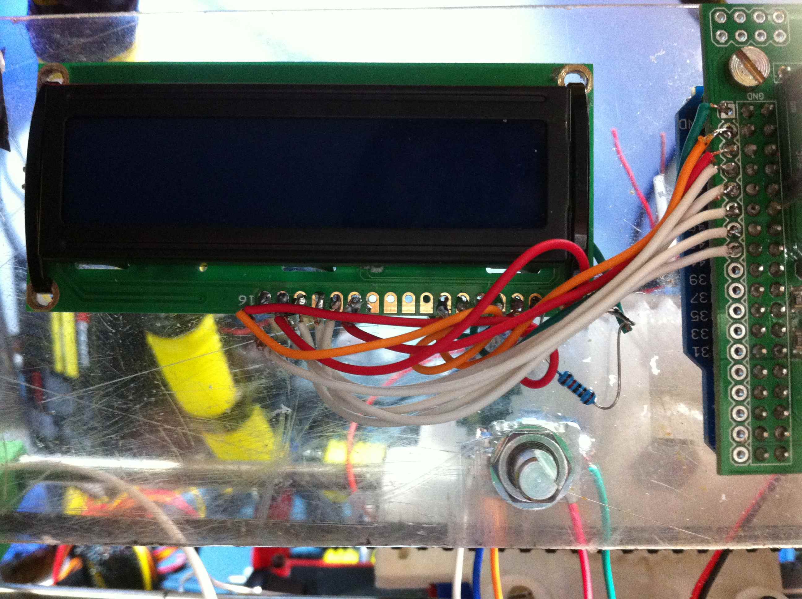
I'm trying to use a 16x2 LCD and wiring like this link: http://sumpod.com/lcd-wiring-and-electronics, but anything happens!
Does anyone have any idea what could be wrong?
I'm trying to use a 16x2 LCD and wiring like this link: http://sumpod.com/lcd-wiring-and-electronics, but anything happens!
Does anyone have any idea what could be wrong?
|
Re: Ramps 1.4 and LCD wiring April 14, 2012 02:16PM |
Registered: 12 years ago Posts: 56 |
|
Re: Ramps 1.4 and LCD wiring April 14, 2012 03:04PM |
Registered: 12 years ago Posts: 11 |
|
Re: Ramps 1.4 and LCD wiring April 14, 2012 04:08PM |
Registered: 12 years ago Posts: 73 |
Em... The way you have wired it bears little resemblance to the link that you posted
Look at my schematic here
You have wired to the pins at the other end of the AUX-4 Port from the sumpod example.
I have this working using pretty much the same wiring as them.
Have a quick review of your wiring versus the schematic on my website (above) see if it is ok.
Alternatively if you are using Marlin you can alter the pins.h file to your own layout.
|
Re: Ramps 1.4 and LCD wiring April 14, 2012 06:43PM |
Registered: 12 years ago Posts: 11 |
|
Re: Ramps 1.4 and LCD wiring April 14, 2012 06:57PM |
Registered: 12 years ago Posts: 73 |
Ok.
Did you use a variable resistor to alter the contrast by adjusting the voltage at pin3 of the LCD?
When you power up your LCD, do you get the test pattern, ie one row blank, the other row completely lit up (a row of blocks)? before the lcd initialises. If you were to program your arduino to do the blink sketch (ie no lcd instructions) this should stay on this way.
Have you tried using a lcd demo sketch from the standard arduino libraries? Getting this to work on RAMPS might be worth doing.
|
Re: Ramps 1.4 and LCD wiring April 14, 2012 07:01PM |
Registered: 12 years ago Posts: 56 |
|
Re: Ramps 1.4 and LCD wiring April 14, 2012 07:09PM |
Registered: 12 years ago Posts: 11 |
|
Re: Ramps 1.4 and LCD wiring April 14, 2012 07:14PM |
Registered: 12 years ago Posts: 73 |
I am guessing then that you need to use a variable resistor as per my schematic. This will allow you to adjust the contrast for your display.
When HD44780 LCD displays start up they normally display that test pattern I described above. If you are not seeing that then there is a good chance that the contrast is set incorrectly.
Its the first thing that I would try so we can rule it out.
When HD44780 LCD displays start up they normally display that test pattern I described above. If you are not seeing that then there is a good chance that the contrast is set incorrectly.
Its the first thing that I would try so we can rule it out.
|
Re: Ramps 1.4 and LCD wiring April 14, 2012 07:17PM |
Registered: 12 years ago Posts: 11 |
|
Re: Ramps 1.4 and LCD wiring April 14, 2012 07:24PM |
Registered: 12 years ago Posts: 11 |
|
Re: Ramps 1.4 and LCD wiring April 14, 2012 07:36PM |
Registered: 12 years ago Posts: 73 |
Not sure which pin will be pin 5,
Your encoder can have several different pins...
Do you mean pin 5 as per my schematic?
Your rotary encoder if it an alps style encoder will have three pins on one side, two pins on the other.
The side with 3 pins will be the encoder part. The middle pin attaches to ground. the other two to pins D33 and D35 on your ramps AUX-4 connector
On the other side of the rotary encoder is two pins that are essentially either terminal of a push button switch. One of these connects to D29 on my schematic, the other connects also to ground. Although you can link it to the middle pin on the other side of the encoder as by now this will be attached to ground..
|
Re: Ramps 1.4 and LCD wiring April 14, 2012 08:23PM |
Registered: 12 years ago Posts: 11 |
Sorry, only registered users may post in this forum.