Welcome! Log In Create A New Profile

Advanced

RAMPS capacitor question

Posted by kman1863 
RAMPS capacitor question
January 08, 2016 07:47AM
Hey guys,

This is probably a better question for an electronics forum, but I thought I'd ask the people who know the RAMPS best first.
On the RAMPS 1.4, a 100µF capacitor corresponds to each of the stepper drivers, but I can't figure out why they're there or how they fit into the circuit itself. Could anyone tell me anything more about these capacitors? I've said all I know about them. On the diagram (attached) they look like they could be in parallel with each motor, but I really can't seem to figure it out. Any info would be awesome.
Thanks!
Kyle
Attachments:
open | download - 800px-RAMPS1_4schematic (1).png (239.5 KB)
Re: RAMPS capacitor question
January 08, 2016 08:00AM
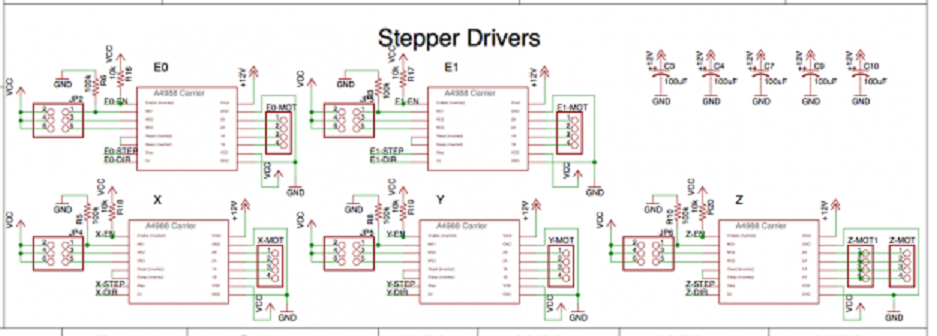
The Caps are across vmot and gnd for each stepper driver.

From the pololu driver page, [www.pololu.com]

"Warning: This carrier board uses low-ESR ceramic capacitors, which makes it susceptible to destructive LC voltage spikes, especially when using power leads longer than a few inches. Under the right conditions, these spikes can exceed the 35 V maximum voltage rating for the A4988 and permanently damage the board, even when the motor supply voltage is as low as 12 V. One way to protect the driver from such spikes is to put a large (at least 47 µF) electrolytic capacitor across motor power (VMOT) and ground somewhere close to the board."

"LC voltage spikes" ie the coils in the in stepper motor

Edited 1 time(s). Last edit at 01/08/2016 08:02AM by Dust.
Sorry, only registered users may post in this forum.

Click here to login