RAMPS 1.3 won't work
Posted by KilgoreTrout
|
RAMPS 1.3 won't work February 20, 2013 06:17PM |
Registered: 11 years ago Posts: 5 |
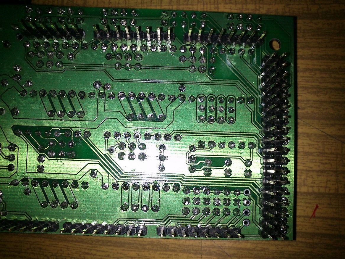
I've just soldered RAMPS 1.3 and I've got trouble making it work. Arduino 2560 seems fine - it works with my old RAMPS. If I connect it all together it doesn't seem to react to USB power or 12V PSU. I've tried with and without D1 diode, with and without thermistors. When it is connected a little thing on Arduino named 269-5G RA227 starts to getting hot and none of LEDs are on.
Please help me find the mistake or tell me what to check.
Please help me find the mistake or tell me what to check.
|
Re: RAMPS 1.3 won't work February 23, 2013 06:37AM |
Registered: 11 years ago Posts: 57 |
Without knowing what the "269-5G RA227" is on your Arduino, I can guess you have a short somewhere on your board, which is going to be difficult to trace.
If the arduino is nonfunctional, it points to a problem with the 5v "vcc" to ground (this would also explain your part getting hot - if it's your voltage regulator it will get warm). Grab a multimeter and test the resistance between VCC and Ground. It should not be "0" when on your lowest setting for resistance.
Do this with everything disconnected from the board (stepper driver carriers, power supply, arduino, thermistors, motors, etc). Examine all of your solder joints to make sure nothing is bridging the little circle where the component should be attached to with the surrounding ground areas.
Nice soldering job btw, pics look good
Good luck on your search - I tried to solder a RAMPS 1.4 (same thing, just with SMD) and gave up after searching for a week for the same problem (though I was able to trace down 3 other shorts I had made with the SMD components).
|
Re: RAMPS 1.3 won't work February 23, 2013 07:47AM |
Registered: 11 years ago Posts: 5 |
mitchese Wrote:
-------------------------------------------------------
> If the arduino is nonfunctional, it points to a
> problem with the 5v "vcc" to ground (this would
> also explain your part getting hot - if it's your
> voltage regulator it will get warm). Grab a
> multimeter and test the resistance between VCC and
> Ground. It should not be "0" when on your lowest
> setting for resistance.
Thanks for reply
I checked the resistance and it is about 0 when on lowest setting - it is connected somehow to GND. I was looking by the path and I can't find how, where you think can be mistake?
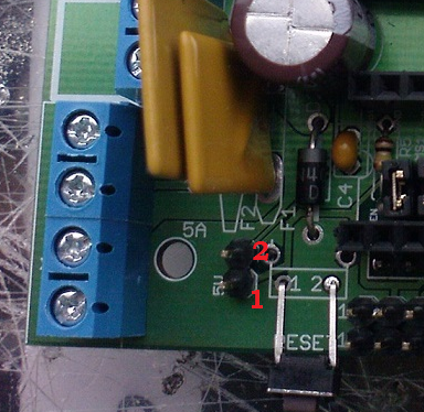
Im not sure if I found VCC correctly, so I signed pins on photo below. The resistance between 1 and GND is 0 and between 2 and GND is infinite.
-------------------------------------------------------
> If the arduino is nonfunctional, it points to a
> problem with the 5v "vcc" to ground (this would
> also explain your part getting hot - if it's your
> voltage regulator it will get warm). Grab a
> multimeter and test the resistance between VCC and
> Ground. It should not be "0" when on your lowest
> setting for resistance.
Thanks for reply
I checked the resistance and it is about 0 when on lowest setting - it is connected somehow to GND. I was looking by the path and I can't find how, where you think can be mistake?
Im not sure if I found VCC correctly, so I signed pins on photo below. The resistance between 1 and GND is 0 and between 2 and GND is infinite.
Sorry, only registered users may post in this forum.