Endstop is triggered but don't stop
Posted by manfred59
|
Endstop is triggered but don't stop January 14, 2015 01:31PM |
Registered: 10 years ago Posts: 41 |
Hi,
I have allready tried, but I did not find a solution.
The x-axis and the y-axis move the right direction also homing direction is ok, but the endstop does not stop the bed or the x-carriage.
I attach the concerned part of my configuration.h file.
My Hardware: Mendel90 Lasercut from www.think3dprint3d.com, with nema 17 steppermotors E3Dv6 hotend and ramps 1.4 with arduino.
I also have tried to turn the endstops and the motors on the ramps - no success.
What the hell is the problem?
Manfred
I have allready tried, but I did not find a solution.
The x-axis and the y-axis move the right direction also homing direction is ok, but the endstop does not stop the bed or the x-carriage.
I attach the concerned part of my configuration.h file.
My Hardware: Mendel90 Lasercut from www.think3dprint3d.com, with nema 17 steppermotors E3Dv6 hotend and ramps 1.4 with arduino.
//=============================Mechanical Settings===========================
//===========================================================================

// Uncomment the following line to enable CoreXY kinematics
// #define COREXY

// coarse Endstop Settings
#define ENDSTOPPULLUPS // Comment this out (using // at the start of the line) to disable the endstop pullup resistors

#ifndef ENDSTOPPULLUPS
  // fine endstop settings: Individual pullups. will be ignored if ENDSTOPPULLUPS is defined
  // #define ENDSTOPPULLUP_XMAX
  // #define ENDSTOPPULLUP_YMAX
  // #define ENDSTOPPULLUP_ZMAX
  // #define ENDSTOPPULLUP_XMIN
  // #define ENDSTOPPULLUP_YMIN
  // #define ENDSTOPPULLUP_ZMIN
#endif

#ifdef ENDSTOPPULLUPS
  #define ENDSTOPPULLUP_XMAX
  #define ENDSTOPPULLUP_YMAX
  #define ENDSTOPPULLUP_ZMAX
  #define ENDSTOPPULLUP_XMIN
  #define ENDSTOPPULLUP_YMIN
  #define ENDSTOPPULLUP_ZMIN
#endif

// The pullups are needed if you directly connect a mechanical endswitch between the signal and ground pins.
const bool X_MIN_ENDSTOP_INVERTING = true; // set to true to invert the logic of the endstop.
const bool Y_MIN_ENDSTOP_INVERTING = true; // set to true to invert the logic of the endstop.
const bool Z_MIN_ENDSTOP_INVERTING = true; // set to true to invert the logic of the endstop.
const bool X_MAX_ENDSTOP_INVERTING = true; // set to true to invert the logic of the endstop.
const bool Y_MAX_ENDSTOP_INVERTING = true; // set to true to invert the logic of the endstop.
const bool Z_MAX_ENDSTOP_INVERTING = true; // set to true to invert the logic of the endstop.
//#define DISABLE_MAX_ENDSTOPS
//#define DISABLE_MIN_ENDSTOPS

// Disable max endstops for compatibility with endstop checking routine
#if defined(COREXY) && !defined(DISABLE_MAX_ENDSTOPS)
  #define DISABLE_MAX_ENDSTOPS
#endif

// For Inverting Stepper Enable Pins (Active Low) use 0, Non Inverting (Active High) use 1
#define X_ENABLE_ON 0
#define Y_ENABLE_ON 0
#define Z_ENABLE_ON 0
#define E_ENABLE_ON 0 // For all extruders

// Disables axis when it's not being used.
#define DISABLE_X false
#define DISABLE_Y false
#define DISABLE_Z false
#define DISABLE_E false // For all extruders
#define DISABLE_INACTIVE_EXTRUDER true //disable only inactive extruders and keep active extruder enabled

#define INVERT_X_DIR false    // for Mendel set to false, for Orca set to true
#define INVERT_Y_DIR false    // for Mendel set to true, for Orca set to false
#define INVERT_Z_DIR true     // for Mendel set to false, for Orca set to true
#define INVERT_E0_DIR false   // for direct drive extruder v9 set to true, for geared extruder set to false
#define INVERT_E1_DIR false    // for direct drive extruder v9 set to true, for geared extruder set to false
#define INVERT_E2_DIR false   // for direct drive extruder v9 set to true, for geared extruder set to false

// ENDSTOP SETTINGS:
// Sets direction of endstops when homing; 1=MAX, -1=MIN
#define X_HOME_DIR -1
#define Y_HOME_DIR -1
#define Z_HOME_DIR 1

#define min_software_endstops true // If true, axis won't move to coordinates less than HOME_POS.
#define max_software_endstops true  // If true, axis won't move to coordinates greater than the defined lengths below.

// Travel limits after homing
#define X_MAX_POS 205
#define X_MIN_POS 0
#define Y_MAX_POS 205
#define Y_MIN_POS 0
#define Z_MAX_POS 200
#define Z_MIN_POS 0

#define X_MAX_LENGTH (X_MAX_POS - X_MIN_POS)
#define Y_MAX_LENGTH (Y_MAX_POS - Y_MIN_POS)
#define Z_MAX_LENGTH (Z_MAX_POS - Z_MIN_POS)
My endstops are connected as common/normally open, but I have allready testet common/normally closed without success!
I also have tried to turn the endstops and the motors on the ramps - no success.
What the hell is the problem?
Manfred
|
Re: Endstop is triggered but don't stop January 14, 2015 07:05PM |
Admin Registered: 13 years ago Posts: 6,998 |
Use the m119 command to the printer to display the endstop status. then manual trigger (with a finger) and re test with m119 to verify they are are are getting triggered as far as the firmware is concerned.
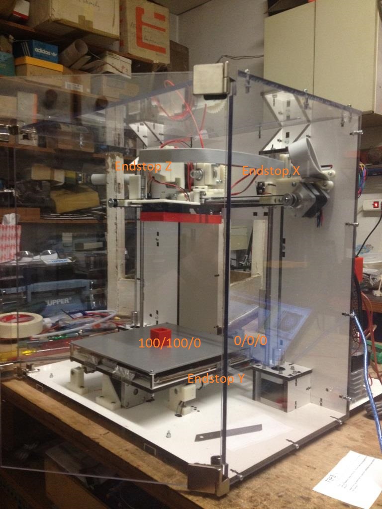
Looking at the picture I see several 'issues'
min endstops are always at left, back and botom of travel. If its not at those locations its not a min endstop
eg I can clearly see the X endstop is on the right hand side. so you need to set #define X_HOME_DIR 1 and make sure that endstop is plugged into the max endstop plug.
I also see the Z is at the top... this is a horrible design desision, so needs Z_HOME_DIR 1 and make sure its plugged into the z max endstop plug. NB This will take several minutes on a standard reprap with a m5 Z thread
I can't see where they put the Y axis endstop.
|
Re: Endstop is triggered but don't stop January 14, 2015 08:28PM |
Registered: 9 years ago Posts: 329 |
Manfred,
I don't see the photos that the last response refers to, but by the looks of your configuration.h, you'll need to be sure that the ends stops are plugged into the proper locations on the RAMPS board.
It is a matter of preference on end stop placement. The location of X and Y end stops determine where your X and Y zeroes and maximums are located, and the orientation of your bed. If you want o,o to be the back-right corner, that's up to you.
Edited 2 time(s). Last edit at 01/14/2015 08:30PM by MindRealm.
-David
Find me online at:
Thingiverse
Instructables.com
LinkedIn
Facebook
Check out my FolgerTech Prusa i3 (plexi) at MindRealm.net
I don't see the photos that the last response refers to, but by the looks of your configuration.h, you'll need to be sure that the ends stops are plugged into the proper locations on the RAMPS board.

It is a matter of preference on end stop placement. The location of X and Y end stops determine where your X and Y zeroes and maximums are located, and the orientation of your bed. If you want o,o to be the back-right corner, that's up to you.
Edited 2 time(s). Last edit at 01/14/2015 08:30PM by MindRealm.
-David
Find me online at:
Thingiverse
Instructables.com
Check out my FolgerTech Prusa i3 (plexi) at MindRealm.net
|
Re: Endstop is triggered but don't stop January 14, 2015 10:29PM |
Admin Registered: 13 years ago Posts: 6,998 |
from his first post he got one of these dodgy looking machines [www.think3dprint3d.com]
|
Re: Endstop is triggered but don't stop January 14, 2015 10:31PM |
Admin Registered: 13 years ago Posts: 6,998 |
re orentation, except that most software has the 0,0,0 point as defined. so if you make it somewhere else, the software controlls will be backwawards or out 90 degrees.. why make life more complicated than it has to be?
And where you want it is also not correct. you must have the X and Y correct in relation to each other or your parts come out backwards!
Edited 1 time(s). Last edit at 01/14/2015 10:33PM by Dust.
And where you want it is also not correct. you must have the X and Y correct in relation to each other or your parts come out backwards!
Edited 1 time(s). Last edit at 01/14/2015 10:33PM by Dust.
|
Re: Endstop is triggered but don't stop January 15, 2015 03:50AM |
Registered: 10 years ago Posts: 41 |
Quote
Dust
Use the m119 command to the printer to display the endstop status. then manual trigger (with a finger) and re test with m119 to verify they are are are getting triggered as far as the firmware is concerned.
Looking at the picture I see several 'issues'
min endstops are always at left, back and botom of travel. If its not at those locations its not a min endstop
eg I can clearly see the X endstop is on the right hand side. so you need to set #define X_HOME_DIR 1 and make sure that endstop is plugged into the max endstop plug.
I also see the Z is at the top... this is a horrible design desision, so needs Z_HOME_DIR 1 and make sure its plugged into the z max endstop plug. NB This will take several minutes on a standard reprap with a m5 Z thread
I can't see where they put the Y axis endstop.
The Y axis endstop is at the front side of the bed and the X axis endstop is on the right.
Manfred
|
Re: Endstop is triggered but don't stop January 15, 2015 03:59AM |
Registered: 10 years ago Posts: 41 |
 There you see all endstops where they are located.
|
Re: Endstop is triggered but don't stop January 15, 2015 08:21AM |
Registered: 9 years ago Posts: 329 |
They all look like max end stops to me. I would suggest plugging them all in like this:
Then change your configuration.h as follows:
-David
Find me online at:
Thingiverse
Instructables.com
LinkedIn
Facebook
Check out my FolgerTech Prusa i3 (plexi) at MindRealm.net

Then change your configuration.h as follows:
//=============================Mechanical Settings===========================
//===========================================================================

// Uncomment the following line to enable CoreXY kinematics
// #define COREXY

// coarse Endstop Settings
#define ENDSTOPPULLUPS // Comment this out (using // at the start of the line) to disable the endstop pullup resistors

#ifndef ENDSTOPPULLUPS
  // fine endstop settings: Individual pullups. will be ignored if ENDSTOPPULLUPS is defined
  // #define ENDSTOPPULLUP_XMAX
  // #define ENDSTOPPULLUP_YMAX
  // #define ENDSTOPPULLUP_ZMAX
  // #define ENDSTOPPULLUP_XMIN
  // #define ENDSTOPPULLUP_YMIN
  // #define ENDSTOPPULLUP_ZMIN
#endif

#ifdef ENDSTOPPULLUPS
  #define ENDSTOPPULLUP_XMAX
  #define ENDSTOPPULLUP_YMAX
  #define ENDSTOPPULLUP_ZMAX
  #define ENDSTOPPULLUP_XMIN
  #define ENDSTOPPULLUP_YMIN
  #define ENDSTOPPULLUP_ZMIN
#endif

// The pullups are needed if you directly connect a mechanical endswitch between the signal and ground pins.
const bool X_MIN_ENDSTOP_INVERTING = true; // set to true to invert the logic of the endstop.
const bool Y_MIN_ENDSTOP_INVERTING = true; // set to true to invert the logic of the endstop.
const bool Z_MIN_ENDSTOP_INVERTING = true; // set to true to invert the logic of the endstop.
const bool X_MAX_ENDSTOP_INVERTING = true; // set to true to invert the logic of the endstop.
const bool Y_MAX_ENDSTOP_INVERTING = true; // set to true to invert the logic of the endstop.
const bool Z_MAX_ENDSTOP_INVERTING = true; // set to true to invert the logic of the endstop.
//#define DISABLE_MAX_ENDSTOPS
#define DISABLE_MIN_ENDSTOPS

// Disable max endstops for compatibility with endstop checking routine
#if defined(COREXY) && !defined(DISABLE_MAX_ENDSTOPS)
  #define DISABLE_MAX_ENDSTOPS
#endif

// For Inverting Stepper Enable Pins (Active Low) use 0, Non Inverting (Active High) use 1
#define X_ENABLE_ON 0
#define Y_ENABLE_ON 0
#define Z_ENABLE_ON 0
#define E_ENABLE_ON 0 // For all extruders

// Disables axis when it's not being used.
#define DISABLE_X false
#define DISABLE_Y false
#define DISABLE_Z false
#define DISABLE_E false // For all extruders
#define DISABLE_INACTIVE_EXTRUDER true //disable only inactive extruders and keep active extruder enabled

#define INVERT_X_DIR false    // for Mendel set to false, for Orca set to true
#define INVERT_Y_DIR false    // for Mendel set to true, for Orca set to false
#define INVERT_Z_DIR true     // for Mendel set to false, for Orca set to true
#define INVERT_E0_DIR false   // for direct drive extruder v9 set to true, for geared extruder set to false
#define INVERT_E1_DIR false    // for direct drive extruder v9 set to true, for geared extruder set to false
#define INVERT_E2_DIR false   // for direct drive extruder v9 set to true, for geared extruder set to false

// ENDSTOP SETTINGS:
// Sets direction of endstops when homing; 1=MAX, -1=MIN
#define X_HOME_DIR -1
#define Y_HOME_DIR -1
#define Z_HOME_DIR -1

#define min_software_endstops true // If true, axis won't move to coordinates less than HOME_POS.
#define max_software_endstops true  // If true, axis won't move to coordinates greater than the defined lengths below.

// Travel limits after homing
#define X_MAX_POS 205
#define X_MIN_POS 0
#define Y_MAX_POS 205
#define Y_MIN_POS 0
#define Z_MAX_POS 200
#define Z_MIN_POS 0

#define X_MAX_LENGTH (X_MAX_POS - X_MIN_POS)
#define Y_MAX_LENGTH (Y_MAX_POS - Y_MIN_POS)
#define Z_MAX_LENGTH (Z_MAX_POS - Z_MIN_POS)
-David
Find me online at:
Thingiverse
Instructables.com
Check out my FolgerTech Prusa i3 (plexi) at MindRealm.net
|
Re: Endstop is triggered but don't stop January 15, 2015 12:03PM |
Registered: 10 years ago Posts: 477 |
Shouldn't the MAX endstops be:
// ENDSTOP SETTINGS:
// Sets direction of endstops when homing; 1=MAX, -1=MIN
#define X_HOME_DIR 1
#define Y_HOME_DIR 1
#define Z_HOME_DIR 1
My updated Instructable on our Prusa i3 Build
[www.instructables.com]
// ENDSTOP SETTINGS:
// Sets direction of endstops when homing; 1=MAX, -1=MIN
#define X_HOME_DIR 1
#define Y_HOME_DIR 1
#define Z_HOME_DIR 1
My updated Instructable on our Prusa i3 Build
[www.instructables.com]
|
Re: Endstop is triggered but don't stop January 15, 2015 12:28PM |
Registered: 9 years ago Posts: 329 |
I don't think so. Wouldn't this make it home to x=205, y=205, z=200 ?
Please let me know if I'm wrong - I don't want to provide bad advice to anyone...
-David
Find me online at:
Thingiverse
Instructables.com
LinkedIn
Facebook
Check out my FolgerTech Prusa i3 (plexi) at MindRealm.net
Please let me know if I'm wrong - I don't want to provide bad advice to anyone...
-David
Find me online at:
Thingiverse
Instructables.com
Check out my FolgerTech Prusa i3 (plexi) at MindRealm.net
|
Re: Endstop is triggered but don't stop January 15, 2015 05:49PM |
Registered: 10 years ago Posts: 41 |
I think the orientation that I now have should work for me. Please see the photos and let me know. If I stand at the back of my printer, so right is right, front is to the endstop of y and z down is to the bed. 0/0/0 is at back left from rear view.
First testprint was a red cube 25mm which ended at 24,96x24,97x24,56 (x/y/z) in ABS 0.35 mm at 245° and 130° bed temp.
The red R orientation is not mirrored!
Manfred
Edited 1 time(s). Last edit at 01/15/2015 05:51PM by manfred59.
First testprint was a red cube 25mm which ended at 24,96x24,97x24,56 (x/y/z) in ABS 0.35 mm at 245° and 130° bed temp.
The red R orientation is not mirrored!
Manfred
Edited 1 time(s). Last edit at 01/15/2015 05:51PM by manfred59.
|
Re: Endstop is triggered but don't stop January 15, 2015 09:11PM |
Registered: 9 years ago Posts: 329 |
Looks good to me! The print results are the most important thing to consider, regarding orientation. The location of 0,0 doesn't matter if you're happy with the results. This is easy to change later if you change your mind!
-David
Find me online at:
Thingiverse
Instructables.com
LinkedIn
Facebook
Check out my FolgerTech Prusa i3 (plexi) at MindRealm.net
-David
Find me online at:
Thingiverse
Instructables.com
Check out my FolgerTech Prusa i3 (plexi) at MindRealm.net
|
Re: Endstop is triggered but don't stop October 30, 2015 10:48PM |
Registered: 8 years ago Posts: 11 |
Hello,
I was installing the mechanical endstops on my printer (Reprap Prusa i2, Gen7 v1.5) and managed to short out between two of the three pins coming off the mechanical switch. This seems to have shorted something on the control board as the endstops aren't working. I replaced the switch that I caused the short with, and the good endstop doesn't work either, so this must be a problem on the control board. The LED on the mechanical switch board had been lighting, and is no longer doing so.
The axis motors are still functioning properly.
Any ideas what I burned on the control board?
Thanks, Aaron
|
Re: Endstop is triggered but don't stop October 31, 2015 07:27AM |
Registered: 13 years ago Posts: 7,616 |
First step would be to measure the voltage on the endstop pin. It should change between < 1.5V and > 3V when the endstop is engaged/released.
| Generation 7 Electronics | Teacup Firmware | RepRap DIY |
|
Re: Endstop is triggered but don't stop October 31, 2015 01:25PM |
Registered: 9 years ago Posts: 329 |
Aaron,
If the steppers are still operating, that rules out damage to the power supply or the poly fuses. I suspect you toasted a trace on the RAMPS board.
OOOOOO <-- Switch Inputs
OOOOOO <-- Ground
OOOOOO <-- VCC
If the VCC is damaged, the LED on the endstop will not light, but the switch should still trigger the input.
If the Switch Input is damages, the LED on the endstop will still light but the switch will not trigger the input
If the Ground is damaged, the LED on the endstop will not light and the switch will not trigger the endstop.
Thus, it seems that the ground trace is the problem, based on your description.
You can test the ground trace by connecting a volt meter (set to 20v DC) as follows:
Turn on the power supply and CAREFULLY probe the following points until power is found (5v DC or more)...
1) Red probe on red D, Black probe on black A
2) Red probe on red D, Black probe on black B
3) Red probe on red D, Black probe on black C
At this point, if you haven't found power, the problem is probably NOT the ground trace...
4) Red probe on red A, Black probe on black D
5) Red probe on red B, Black probe on black D
6) Red probe on red C, Black probe on black D
At this point, if you haven't found power, make sure the power is on.
The red D is the power that is common to the Arduino VCC. If there is no voltage here, none of the RAMPS VCC points should have power, thus the steppers would not work.
The black D is the ground point for the extruder stepper motor. It there is no ground here, the extruder stepper would not work.
The black C is the last point on the ground trace before is narrows before feeding the second extruder stepper driver, then the end stop grounds. The weak spot, where the trace is likely to be bad, is between this point and the black A.
-David
Find me online at:
Thingiverse
Instructables.com
LinkedIn
Facebook
Check out my FolgerTech Prusa i3 (plexi) at MindRealm.net
If the steppers are still operating, that rules out damage to the power supply or the poly fuses. I suspect you toasted a trace on the RAMPS board.
OOOOOO <-- Switch Inputs
OOOOOO <-- Ground
OOOOOO <-- VCC
If the VCC is damaged, the LED on the endstop will not light, but the switch should still trigger the input.
If the Switch Input is damages, the LED on the endstop will still light but the switch will not trigger the input
If the Ground is damaged, the LED on the endstop will not light and the switch will not trigger the endstop.
Thus, it seems that the ground trace is the problem, based on your description.
You can test the ground trace by connecting a volt meter (set to 20v DC) as follows:
Turn on the power supply and CAREFULLY probe the following points until power is found (5v DC or more)...
1) Red probe on red D, Black probe on black A
2) Red probe on red D, Black probe on black B
3) Red probe on red D, Black probe on black C
At this point, if you haven't found power, the problem is probably NOT the ground trace...
4) Red probe on red A, Black probe on black D
5) Red probe on red B, Black probe on black D
6) Red probe on red C, Black probe on black D
At this point, if you haven't found power, make sure the power is on.
The red D is the power that is common to the Arduino VCC. If there is no voltage here, none of the RAMPS VCC points should have power, thus the steppers would not work.
The black D is the ground point for the extruder stepper motor. It there is no ground here, the extruder stepper would not work.
The black C is the last point on the ground trace before is narrows before feeding the second extruder stepper driver, then the end stop grounds. The weak spot, where the trace is likely to be bad, is between this point and the black A.

-David
Find me online at:
Thingiverse
Instructables.com
Check out my FolgerTech Prusa i3 (plexi) at MindRealm.net
|
Re: Endstop is triggered but don't stop November 13, 2015 05:39PM |
Registered: 8 years ago Posts: 11 |
|
Re: Endstop is triggered but don't stop November 24, 2015 02:26AM |
Registered: 9 years ago Posts: 245 |
I know you managed to solve it, but I'll pipe in anyway
Recently made an Instructables on how to configure endstops. Using everyday language and not Electronics talk:
Configuring Endstops on Ramps 1.4 with Marlin firmware - @section homing
Al so JUST made the follow up Motion Configuration on Ramps 1.4 with Marlin firmware @section machine to it. Also in everyday language
Regarding endstops triggering but not stopping the axes.
Look in the Configuration_adv.h sketch for below code. If that is enabled the endstosp will only be used for homing and thus can be triggere without stopping the printer - usefull when you need to configure z-offset.
My Instructables - both total newbie instructables and some for intermediate users.
My Designs on Thingiverse
YouTube channel containing a few 3D printing videos - they are videos for my Instructables, and mostly not standalone.
Ultius / Tantillus Thingiverse Group
Recently made an Instructables on how to configure endstops. Using everyday language and not Electronics talk:
Configuring Endstops on Ramps 1.4 with Marlin firmware - @section homing
Al so JUST made the follow up Motion Configuration on Ramps 1.4 with Marlin firmware @section machine to it. Also in everyday language
Regarding endstops triggering but not stopping the axes.
Look in the Configuration_adv.h sketch for below code. If that is enabled the endstosp will only be used for homing and thus can be triggere without stopping the printer - usefull when you need to configure z-offset.
#define ENDSTOPS_ONLY_FOR_HOMING // If defined the endstops will only be used for homing
My Instructables - both total newbie instructables and some for intermediate users.
My Designs on Thingiverse
YouTube channel containing a few 3D printing videos - they are videos for my Instructables, and mostly not standalone.
Ultius / Tantillus Thingiverse Group
|
Re: Endstop is triggered but don't stop November 10, 2016 06:35AM |
Registered: 7 years ago Posts: 5 |
Could somebody please help me.
I am struggleing to get a single print out from my delta printer
I use Atmega 2560
I have mechanical end stops normally close
this is what it says with M119
SENDING:M119
Reporting endstop status
x_max: TRIGGERED
y_max: TRIGGERED
z_max: TRIGGERED
when I manually press them they open as below
SENDING:M119
Reporting endstop status
x_max: TRIGGERED
y_max: open
z_max: TRIGGERED
I guess above setting is alright.
but the problem is when i press the home button x and y axis moves around 1cm each time i press home button.
below is the code
i have tried changing DIR 1 (- and 1) doesn`t give any good results
/ coarse Endstop Settings
#define ENDSTOPPULLUPS // Comment this out (using // at the start of the line) to disable the endstop pullup resistors
#ifndef ENDSTOPPULLUPS
// fine Enstop settings: Individual Pullups. will be ignored if ENDSTOPPULLUPS is defined
// #define ENDSTOPPULLUP_XMAX
// #define ENDSTOPPULLUP_YMAX
// #define ENDSTOPPULLUP_ZMAX
// #define ENDSTOPPULLUP_XMIN
// #define ENDSTOPPULLUP_YMIN
// #define ENDSTOPPULLUP_ZMIN
#endif
#ifdef ENDSTOPPULLUPS
#define ENDSTOPPULLUP_XMAX
#define ENDSTOPPULLUP_YMAX
#define ENDSTOPPULLUP_ZMAX
#define ENDSTOPPULLUP_XMIN
#define ENDSTOPPULLUP_YMIN
#define ENDSTOPPULLUP_ZMIN
#endif
// The pullups are needed if you directly connect a mechanical endswitch between the signal and ground pins.
const bool X_MIN_ENDSTOP_INVERTING = true; // set to true to invert the logic of the endstop.
const bool Y_MIN_ENDSTOP_INVERTING = true; // set to true to invert the logic of the endstop.
const bool Z_MIN_ENDSTOP_INVERTING = true; // set to true to invert the logic of the endstop.
const bool X_MAX_ENDSTOP_INVERTING = true; // set to true to invert the logic of the endstop.
const bool Y_MAX_ENDSTOP_INVERTING = true; // set to true to invert the logic of the endstop.
const bool Z_MAX_ENDSTOP_INVERTING = true; // set to true to invert the logic of the endstop.
//#define DISABLE_MAX_ENDSTOPS
#define DISABLE_MIN_ENDSTOPS
// Disable max endstops for compatibility with endstop checking routine
#if defined(COREXY) && !defined(DISABLE_MAX_ENDSTOPS)
#define DISABLE_MAX_ENDSTOPS
#endif
// For Inverting Stepper Enable Pins (Active Low) use 0, Non Inverting (Active High) use 1
#define X_ENABLE_ON 0
#define Y_ENABLE_ON 0
#define Z_ENABLE_ON 0
#define E_ENABLE_ON 0 // For all extruders
// Disables axis when it's not being used.
#define DISABLE_X false
#define DISABLE_Y false
#define DISABLE_Z false
#define DISABLE_E false // For all extruders
#define INVERT_X_DIR false // for Mendel set to false, for Orca set to true
#define INVERT_Y_DIR false // for Mendel set to true, for Orca set to false
#define INVERT_Z_DIR true // for Mendel set to false, for Orca set to true
#define INVERT_E0_DIR false // for direct drive extruder v9 set to true, for geared extruder set to false
#define INVERT_E1_DIR false // for direct drive extruder v9 set to true, for geared extruder set to false
#define INVERT_E2_DIR false // for direct drive extruder v9 set to true, for geared extruder set to false
// ENDSTOP SETTINGS:
// Sets direction of endstops when homing; 1=MAX, -1=MIN
#define X_HOME_DIR 1
#define Y_HOME_DIR 1
#define Z_HOME_DIR -1
#define min_software_endstops true // If true, axis won't move to coordinates less than HOME_POS.
#define max_software_endstops true // If true, axis won't move to coordinates greater than the defined lengths below.
// Travel limits after homing
#define X_MAX_POS 205
#define X_MIN_POS 0
#define Y_MAX_POS 205
#define Y_MIN_POS 0
#define Z_MAX_POS MANUAL_Z_HOME_POS
#define Z_MIN_POS 0
#define X_MAX_LENGTH (X_MAX_POS - X_MIN_POS)
#define Y_MAX_LENGTH (Y_MAX_POS - Y_MIN_POS)
#define Z_MAX_LENGTH (Z_MAX_POS - Z_MIN_POS)
// The position of the homing switches
#define MANUAL_HOME_POSITIONS // If defined, MANUAL_*_HOME_POS below will be used
#define BED_CENTER_AT_0_0 // If defined, the center of the bed is at (X=0, Y=0)
//Manual homing switch locations:
// For deltabots this means top and center of the cartesian print volume.
#define MANUAL_X_HOME_POS 0
#define MANUAL_Y_HOME_POS 0
#define MANUAL_Z_HOME_POS 258 // For delta: Distance between nozzle and print surface after homing.
could you please tell me what I am doing wrong.
my wiring done as describe in previous post onthis thread
|
Re: Endstop is triggered but don't stop November 10, 2016 05:59PM |
Admin Registered: 13 years ago Posts: 6,998 |
did you start with a delta example configuration? I don’t think so... see [github.com]
endstops are logicaly backwards, they should say open when they are not being triggered, and triggered when they are being triggered. regardless of the electrical state
find, and change to false, eg
const bool X_MAX_ENDSTOP_INVERTING = false; // set to true to invert the logic of the endstop.
const bool Y_MAX_ENDSTOP_INVERTING = false; // set to true to invert the logic of the endstop.
const bool Z_MAX_ENDSTOP_INVERTING = false; // set to true to invert the logic of the endstop.
find homeing direction and edit to all max, eg
#define X_HOME_DIR 1 // deltas always home to max
#define Y_HOME_DIR 1
#define Z_HOME_DIR 1
But personally I would start again with one of the detla example configurations, or your going to be tweaking the configuration for months.
Edited 1 time(s). Last edit at 11/10/2016 06:01PM by Dust.
|
Re: Endstop is triggered but don't stop December 13, 2016 07:39PM |
Registered: 7 years ago Posts: 5 |
Please advise.
I tried comment out:
//#define ENDSTOPS_ONLY_FOR_HOMING // If defined the endstops will only be used for homing
But my Z endstop triggered does not stop the axis moving until hits the hotend on bed!
My printer has the Z home at top (instead of bottom).
Edited 1 time(s). Last edit at 12/13/2016 07:40PM by leadpan.
|
Re: Endstop is triggered but don't stop November 09, 2017 05:12AM |
Registered: 6 years ago Posts: 5 |
Hey guys,
I am having a similar problem, but the replys to the question do not solve the problem, nore could I find any other helpful sorce on google.
I am using a RUMBA board to control whats left of a HICTOP MK2. The endstops are at the bottom/rear/left of the printer and connected to x/y/z_min. Using M119, I can confirm that the endstops are triggered when I manually push them. The endstop of the z-axis has an inductive endstop with a LED, so i can even see when it is triggered. I got the LCD working and I can manually drive the axis into the + directions (upwards, to the front, right) using either the LCD or a command promp using the USB.The traveling distances seem to be approximately right.
Here is the issue: When I start the homing, the z-axis starts to move downwards, but ignores the endstop and keeps traveling downwards untill I disconnect the power (I can even see the LED going on). When I have it starting from a higher position, it travels ~4 cm downwards, stops midair and then starts homing the other axes, which are homing perfectly. After that, it just starts to travel upward till infinty (until I have to kill the power supply).
I have tried it with #define Z_MIN_PROBE_USES_Z_MIN_ENDSTOP_PIN or alternatively with #define Z_MIN_PROBE_ENDSTOP in combination with #define PROBE_MANUALLY and the probe connected to either z_min or z_max. Also, I exchanged the inductive sensor to one of the switch endstops of the other axis. Non of this led to a different result. Again, when I drive the axis to the endstops manually M119 confirms they are triggered.
Here is what I belive to be the relevant parts of the configurations file. If any other are needed, let me know. Any help or ideas are highly appreciated:
//===========================================================================
//============================== Endstop Settings ===========================
//===========================================================================
// @section homing
// Specify here all the endstop connectors that are connected to any endstop or probe.
// Almost all printers will be using one per axis. Probes will use one or more of the
// extra connectors. Leave undefined any used for non-endstop and non-probe purposes.
#define USE_XMIN_PLUG
#define USE_YMIN_PLUG
#define USE_ZMIN_PLUG
//#define USE_XMAX_PLUG
//#define USE_YMAX_PLUG
//#define USE_ZMAX_PLUG
// coarse Endstop Settings
#define ENDSTOPPULLUPS // Comment this out (using // at the start of the line) to disable the endstop pullup resistors
#if DISABLED(ENDSTOPPULLUPS)
// fine endstop settings: Individual pullups. will be ignored if ENDSTOPPULLUPS is defined
//#define ENDSTOPPULLUP_XMAX
//#define ENDSTOPPULLUP_YMAX
//#define ENDSTOPPULLUP_ZMAX
//#define ENDSTOPPULLUP_XMIN
//#define ENDSTOPPULLUP_YMIN
//#define ENDSTOPPULLUP_ZMIN
//#define ENDSTOPPULLUP_ZMIN_PROBE
#endif
// Mechanical endstop with COM to ground and NC to Signal uses "false" here (most common setup).
#define X_MIN_ENDSTOP_INVERTING true // set to true to invert the logic of the endstop.
#define Y_MIN_ENDSTOP_INVERTING true // set to true to invert the logic of the endstop.
#define Z_MIN_ENDSTOP_INVERTING true // set to true to invert the logic of the endstop.
#define X_MAX_ENDSTOP_INVERTING false // set to true to invert the logic of the endstop.
#define Y_MAX_ENDSTOP_INVERTING false // set to true to invert the logic of the endstop.
#define Z_MAX_ENDSTOP_INVERTING false // set to true to invert the logic of the endstop.
#define Z_MIN_PROBE_ENDSTOP_INVERTING true // set to true to invert the logic of the probe.
// Enable this feature if all enabled endstop pins are interrupt-capable.
// This will remove the need to poll the interrupt pins, saving many CPU cycles.
//#define ENDSTOP_INTERRUPTS_FEATURE
...
//===========================================================================
//============================= Z Probe Options =============================
//===========================================================================
// @section probes
//
// See [marlinfw.org]
//
/**
* Z_MIN_PROBE_USES_Z_MIN_ENDSTOP_PIN
*
* Enable this option for a probe connected to the Z Min endstop pin.
*/
#define Z_MIN_PROBE_USES_Z_MIN_ENDSTOP_PIN
/**
* Z_MIN_PROBE_ENDSTOP
*
* Enable this option for a probe connected to any pin except Z-Min.
* (By default Marlin assumes the Z-Max endstop pin.)
* To use a custom Z Probe pin, set Z_MIN_PROBE_PIN below.
*
* - The simplest option is to use a free endstop connector.
* - Use 5V for powered (usually inductive) sensors.
*
* - RAMPS 1.3/1.4 boards may use the 5V, GND, and Aux4->D32 pin:
* - For simple switches connect...
* - normally-closed switches to GND and D32.
* - normally-open switches to 5V and D32.
*
* WARNING: Setting the wrong pin may have unexpected and potentially
* disastrous consequences. Use with caution and do your homework.
*
*/
//#define Z_MIN_PROBE_ENDSTOP
/**
* Probe Type
*
* Allen Key Probes, Servo Probes, Z-Sled Probes, FIX_MOUNTED_PROBE, etc.
* Activate one of these to use Auto Bed Leveling below.
*/
/**
* The "Manual Probe" provides a means to do "Auto" Bed Leveling without a probe.
* Use G29 repeatedly, adjusting the Z height at each point with movement commands
* or (with LCD_BED_LEVELING) the LCD controller.
*/
//#define PROBE_MANUALLY
/**
* A Fix-Mounted Probe either doesn't deploy or needs manual deployment.
* (e.g., an inductive probe or a nozzle-based probe-switch.)
*/
//#define FIX_MOUNTED_PROBE
|
Re: Endstop is triggered but don't stop November 09, 2017 08:39AM |
Registered: 6 years ago Posts: 1,863 |
|
Re: Endstop is triggered but don't stop November 09, 2017 06:15PM |
Registered: 6 years ago Posts: 5 |
Hey Roberts,
thanks for the reply. Seems like a good idea. However, it unfortunately still gives the same result: Endstop triggered, but homing does not stop. Are you using the HICTOP OEM board or something different? Would you mind sending me your complete configurations code, so I can compare it line-by-line?
Thanks again and best regards
|
Re: Endstop is triggered but don't stop November 09, 2017 09:39PM |
Admin Registered: 13 years ago Posts: 6,998 |
and what are you homing directions set to?
"endstop with a LED, so i can even see when it is triggered"
doesnt mean the controller is seeing it...
make sure z probe led is off
send printer a M119, it should say Z open
hold a steel ruler or other metal thing under the probe, led should be on
send the printer a M119, Z should now say triggered
I suspect the latter is not happening
Edited 1 time(s). Last edit at 11/09/2017 09:39PM by Dust.
|
Re: Endstop is triggered but don't stop November 10, 2017 03:26AM |
Registered: 6 years ago Posts: 5 |
Hey Dust,
my homing directions are set to:
// Direction of endstops when homing; 1=MAX, -1=MIN
// :[-1,1]
#define X_HOME_DIR -1
#define Y_HOME_DIR -1
#define Z_HOME_DIR -1
and the endstops connected to Min.
yeah, I did that, many times, using a steel ruler or the bed itself. It works the way you describe it. I even changed from a "more complex" (three wire) inductive probe to a simple switch. The triggering is detected how it should be without homing, but ignored during homing. That is the strange thing...
Any other possible ideas?
my homing directions are set to:
// Direction of endstops when homing; 1=MAX, -1=MIN
// :[-1,1]
#define X_HOME_DIR -1
#define Y_HOME_DIR -1
#define Z_HOME_DIR -1
and the endstops connected to Min.
Quote
send printer a M119, it should say Z open
hold a steel ruler or other metal thing under the probe, led should be on
send the printer a M119, Z should now say triggered
yeah, I did that, many times, using a steel ruler or the bed itself. It works the way you describe it. I even changed from a "more complex" (three wire) inductive probe to a simple switch. The triggering is detected how it should be without homing, but ignored during homing. That is the strange thing...
Any other possible ideas?
|
Re: Endstop is triggered but don't stop November 10, 2017 03:04PM |
Registered: 9 years ago Posts: 329 |
Looks like a bed geometry thing to me... The firmware (Marlin?) needs to know where the travel limits are. Manually move the nozzle down to the print bed with the printer powered down then right after turning on the power run M114 and post the results here. Also, attach your configuration.h file to the reply. I'll take a look.
-David
Find me online at:
Thingiverse
Instructables.com
LinkedIn
Facebook
Check out my FolgerTech Prusa i3 (plexi) at MindRealm.net
-David
Find me online at:
Thingiverse
Instructables.com
Check out my FolgerTech Prusa i3 (plexi) at MindRealm.net
|
Re: Endstop is triggered but don't stop November 11, 2017 01:55PM |
Registered: 6 years ago Posts: 5 |
Hey MindRealm,
sorry, I forgott to mention, it is Marlin in deed.
I did as you said and the result of the M114 was:
> M119
< Reporting endstop status
< x_min: open
< y_min: open
< z_min: TRIGGERED
> M114
< X:0.00 Y:0.00 Z:0.00 E:0.00 Count X:0 Y:0 Z:0
Makes sense to me, right?
I attached the file, if you can give me any advice it would be very helpful. Thanks in advance.
Best wishes
|
Re: Endstop is triggered but don't stop November 12, 2017 06:27PM |
Registered: 9 years ago Posts: 329 |
I will take a look at the configuration.h but also need a little more info first...
Do you have an LCD with a knob? If so, there may be some geometry settings saved in its memory.
- Shut down power to the printer and carefully unplug the LCD from the RAMPS card (can be unplugged either at the LCD or at the RAMPS) and note where each cable was connected. They fit the same and it is possible to swap them by accident - be careful.
After unplugging the LCD, power the printer back up and try to home the axes again and let me know if the problem still exists.
Thanks
-David
Find me online at:
Thingiverse
Instructables.com
LinkedIn
Facebook
Check out my FolgerTech Prusa i3 (plexi) at MindRealm.net
Do you have an LCD with a knob? If so, there may be some geometry settings saved in its memory.
- Shut down power to the printer and carefully unplug the LCD from the RAMPS card (can be unplugged either at the LCD or at the RAMPS) and note where each cable was connected. They fit the same and it is possible to swap them by accident - be careful.
After unplugging the LCD, power the printer back up and try to home the axes again and let me know if the problem still exists.
Thanks
-David
Find me online at:
Thingiverse
Instructables.com
Check out my FolgerTech Prusa i3 (plexi) at MindRealm.net
|
Re: Endstop is triggered but don't stop November 13, 2017 05:26AM |
Registered: 6 years ago Posts: 5 |
Hey MindRealm,
thanks for your reply. After one weekend of investigations, I was able to finally find that tricky error a few hours befor your post, but as it was way past midnight for me I am just replying now. As maybe somebody else one day might have the same error, I will post a detailed solution here.
In fact, it was the combination of three errors
1. The calibaration of the z-Axis was off. For some reasons, HICTOP is using an M8 screw with a pitch of 2 mm instead of the regular 1.25 mm per rotation. In addition, the one of the microstepping switches of the RUMBA was not pushed all the way down (but seemed to be), which led to an 1/8 insted of a 1/32 microstepping. As an result, the axis traveled far more than they should have.
2. Hictop set homing to going only left, then rear and than bottom. Marlin instead makes it more intelligent, by first moving the nozzle a little up to avoid collission, which I did not know.
3. The direction of the z-Axis was wrong. Before homing, Marlin allows you only to move right, front and up, whereas I thought it should be down.
So when the homing was started, the z-Axis moved down, but that was not a movement intended for homing but for moving the Axis out of the way of the x and y axis. That is the reason why, when I stared the axis from a higher point, the homing of x and y started after a short distance. The upward movement of the z axis then was the "real" homing into the wrong direction, and that was why it never stopped.
So, after recalibration and inverting the movement direction, everything works perfectely.
Thanks guys for your help
p.s. For completeness, the LCD has a turning knob, but I unplugged it most of the time anyways as the LCD prevents an uploading of marlin from the PC when plugged in. So this was not the issue.
Sorry, only registered users may post in this forum.