Ramps 1.4 with graphical display: China LCD-Board Robotale 12864 layout wrong?
Posted by Chris D.
|
Ramps 1.4 with graphical display: China LCD-Board Robotale 12864 layout wrong? February 12, 2015 01:00PM |
Registered: 9 years ago Posts: 49 |
Hi folks,
I'm new to 3D printing and want to build my own 3D printer using Ramps 1.4 with graphical display.
Ok, the mechanical parts are still on their way so I tried the electronics which arrived yesterday.
I'm quite new to Arduino (usually I am programming the AVRs directly via C,C++), so I hope I did everything right on the software side (yes, I uncomment #define REPRAP_DISCOUNT_FULL_GRAPHIC_SMART_CONTROLLER etc.)
Ok, I have programmed the Arduino board with the current development version of Marlin 1.0.2 and in the serial console I get some messages of the software until I get a "echo:sd init fail" error which is ok because I haven't inserted a SD card :-)
Now I could press the incremetal switch button and got beeps from the buzzer, but the display stayed empty (the backlight worked).
I checked the cables etc. but nothing made the LCD working.
I have programmed such graphical displays in the past and knew that the programming data flow via DB4-DB7 in most cases. Due to the lack of a pin connecting diagram of the two 10 pin headers I tried to measure the connection from the LCD module to the two headers for all relevand pins (DB4-DB/, E, RS,R/W) but didn't find a wiring for DB4-DB7!
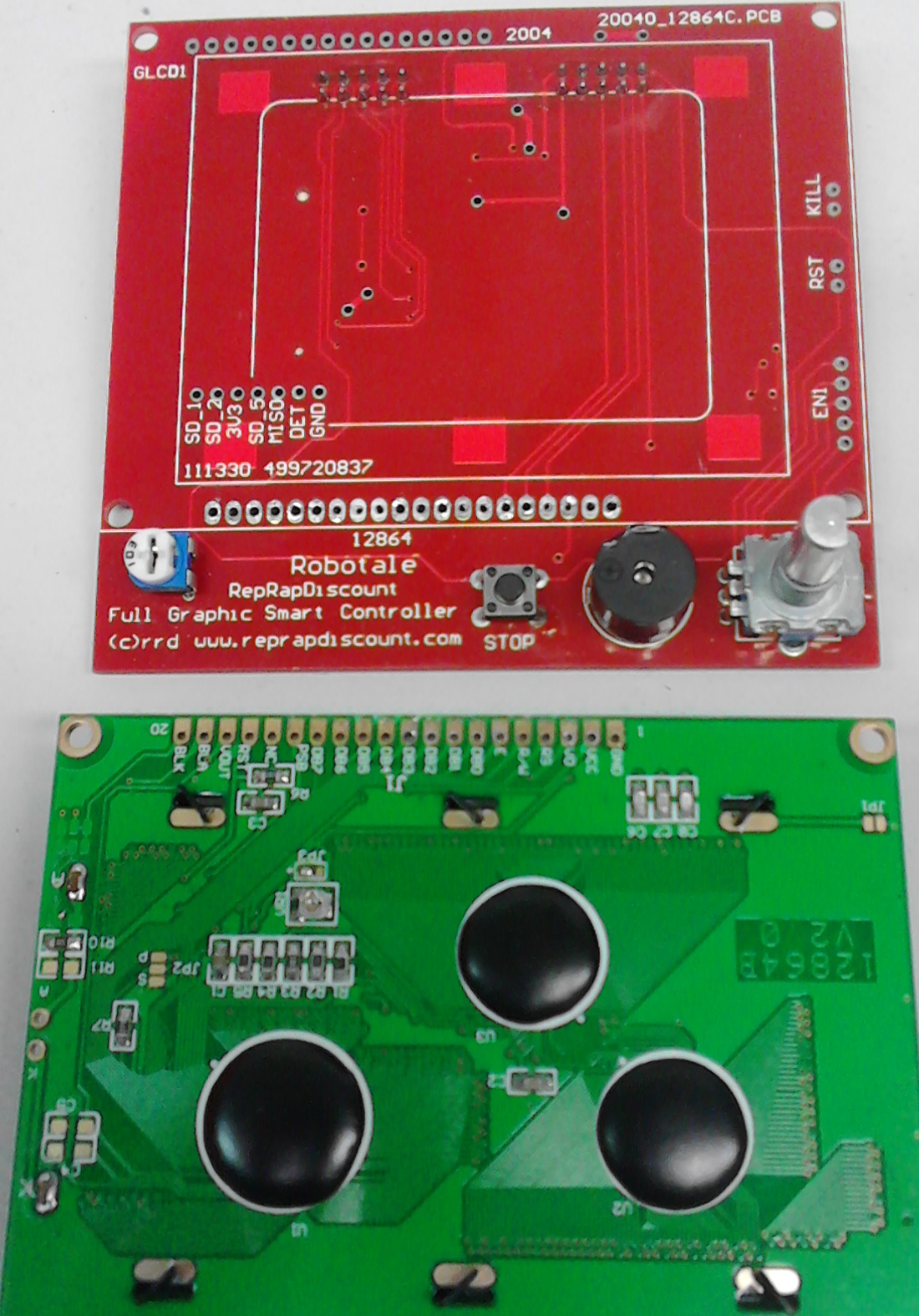
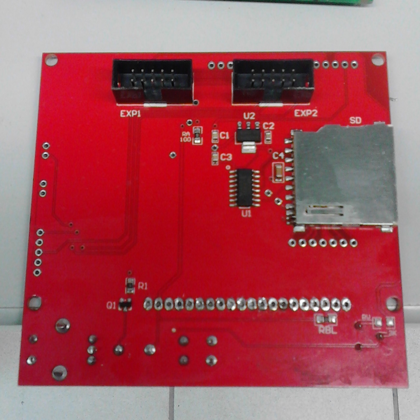
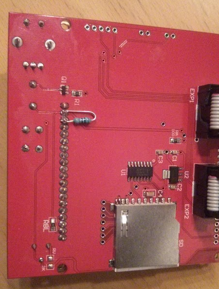
This seemed to be strange so I desoldered the display from its board (see photos) and found my measurements confirmed:
There are no connections to any of the LCD data lines. Only E, RS and R/W are connected!
Most other pins of the LCD header are connected to the test point (?) row of vias obove them.
The red board is a simple double layers board so there are no internal layers etc. There are simply no data connections!
So the reason for no display data seems to be a wrong layout!
Can anyone tell me the correct pin connections of the two 10 pin headers? It seems that I have to wire the connections by myself.
What's about the connected R/W pin? In the Marlin definition I never found defintions for this pin, only E and RS. I also never used R/W because I didn't want to read data from the display :-)
I bought my set via aliexpress and I think many, many of not working displays are not working due to this wrong layout which seems to be a (bad!) clone of a Robotale layout.
Or have I missed something?
Best regards,
Chris
Edited 1 time(s). Last edit at 02/12/2015 01:02PM by Chris D..
I'm new to 3D printing and want to build my own 3D printer using Ramps 1.4 with graphical display.
Ok, the mechanical parts are still on their way so I tried the electronics which arrived yesterday.
I'm quite new to Arduino (usually I am programming the AVRs directly via C,C++), so I hope I did everything right on the software side (yes, I uncomment #define REPRAP_DISCOUNT_FULL_GRAPHIC_SMART_CONTROLLER etc.)
Ok, I have programmed the Arduino board with the current development version of Marlin 1.0.2 and in the serial console I get some messages of the software until I get a "echo:sd init fail" error which is ok because I haven't inserted a SD card :-)
Now I could press the incremetal switch button and got beeps from the buzzer, but the display stayed empty (the backlight worked).
I checked the cables etc. but nothing made the LCD working.
I have programmed such graphical displays in the past and knew that the programming data flow via DB4-DB7 in most cases. Due to the lack of a pin connecting diagram of the two 10 pin headers I tried to measure the connection from the LCD module to the two headers for all relevand pins (DB4-DB/, E, RS,R/W) but didn't find a wiring for DB4-DB7!
This seemed to be strange so I desoldered the display from its board (see photos) and found my measurements confirmed:
There are no connections to any of the LCD data lines. Only E, RS and R/W are connected!
Most other pins of the LCD header are connected to the test point (?) row of vias obove them.
The red board is a simple double layers board so there are no internal layers etc. There are simply no data connections!
So the reason for no display data seems to be a wrong layout!
Can anyone tell me the correct pin connections of the two 10 pin headers? It seems that I have to wire the connections by myself.
What's about the connected R/W pin? In the Marlin definition I never found defintions for this pin, only E and RS. I also never used R/W because I didn't want to read data from the display :-)
I bought my set via aliexpress and I think many, many of not working displays are not working due to this wrong layout which seems to be a (bad!) clone of a Robotale layout.
Or have I missed something?
Best regards,
Chris
Edited 1 time(s). Last edit at 02/12/2015 01:02PM by Chris D..
|
Re: Ramps 1.4 with graphical display: China LCD-Board Robotale 12864 layout wrong? February 12, 2015 06:12PM |
Registered: 10 years ago Posts: 14,672 |
The display uses a graphics controller chip (ST7920 I think) that can operate in either parallel or serial (SPI-like) mode depending on whether the PSB pin is connected to ground or to +5V. In serial mode, the E pin is the clock and the R/W pin carries the data.
Large delta printer [miscsolutions.wordpress.com], E3D tool changer, Robotdigg SCARA printer, Crane Quad and Ormerod
Disclosure: I design Duet electronics and work on RepRapFirmware, [duet3d.com].
Large delta printer [miscsolutions.wordpress.com], E3D tool changer, Robotdigg SCARA printer, Crane Quad and Ormerod
Disclosure: I design Duet electronics and work on RepRapFirmware, [duet3d.com].
|
Re: Ramps 1.4 with graphical display: China LCD-Board Robotale 12864 layout wrong? February 13, 2015 02:47AM |
Registered: 9 years ago Posts: 49 |
Hi!
Ahhh, thank you very much - I didn't know that. Then the layout seems to be correct and I must have done a mistake elsewhere. I will check with my oscilloscope/LA if the SPI works correctly.
Thanks again and regards,
Chris
Edited 1 time(s). Last edit at 02/13/2015 02:48AM by Chris D..
Ahhh, thank you very much - I didn't know that. Then the layout seems to be correct and I must have done a mistake elsewhere. I will check with my oscilloscope/LA if the SPI works correctly.
Thanks again and regards,
Chris
Edited 1 time(s). Last edit at 02/13/2015 02:48AM by Chris D..
|
Re: Ramps 1.4 with graphical display: China LCD-Board Robotale 12864 layout wrong? February 13, 2015 10:07AM |
Registered: 9 years ago Posts: 8 |
Hi,
I'm also in the middle of building my first printer and I am experiencing the same problem with a display that lights up but doesn't display any text. I am using the same type of display (Robotale clone) bought from aliexpress together with an arduino and a RAMPS 1.4 board (also clones).
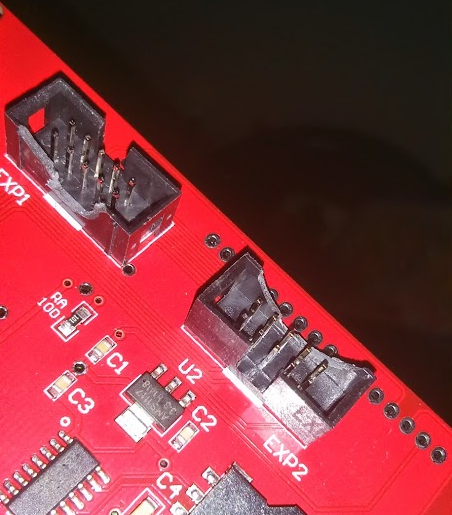
One thing I noted on my display was that the cable connector guides on the back of the LCD controller was facing in different directions. This seemed odd to me and a bit of googling confirmed that both connector guides should be in the same direction. I have manually "fixed" the connectors to allow the cable to be inserted both ways (see attached picture).
If you have the possibility to look up the pinout for the LCD pins I would be really grateful By knowing what pins to trace this should be quite easy to figure out.
Best regards,
Henrik
I'm also in the middle of building my first printer and I am experiencing the same problem with a display that lights up but doesn't display any text. I am using the same type of display (Robotale clone) bought from aliexpress together with an arduino and a RAMPS 1.4 board (also clones).
One thing I noted on my display was that the cable connector guides on the back of the LCD controller was facing in different directions. This seemed odd to me and a bit of googling confirmed that both connector guides should be in the same direction. I have manually "fixed" the connectors to allow the cable to be inserted both ways (see attached picture).
If you have the possibility to look up the pinout for the LCD pins I would be really grateful
By knowing what pins to trace this should be quite easy to figure out.Best regards,
Henrik
|
Re: Ramps 1.4 with graphical display: China LCD-Board Robotale 12864 layout wrong? February 13, 2015 11:01AM |
Registered: 9 years ago Posts: 49 |
Hi Henrik,
yes, your cable connectors are soldered in the wrong direction (but may be they also switched the cable plugs so that the direction would be right again?)
But that should be easy to check, if you search for the GND pins of your LCD board and the RAMPS board and check if there is a connection between them.
For my LCD board I resoldered the module to the pcb via flat cable and checked the three serial wires E, R/W, RS via oscilloscope. I found some data streams on them, and the data streams changes when I press the incremental encoder - but nothing is shown :-(
May be the contrast level is not ok? I checked the V0 voltage and I am able to justage it via the trimmer resistor from 1V to 0V. Is this ok?
Best regards,
Chris
|
Re: Ramps 1.4 with graphical display: China LCD-Board Robotale 12864 layout wrong? February 13, 2015 05:32PM |
Registered: 9 years ago Posts: 8 |
Hi Chris,
Thanks for your reply and advice on how to connect the cables
Using the GND pins I managed to find out the correct plug directions but I still had nothing visible on the display (only blue background).
By looking at the serial console I could verify that the SD card reader was at least partially working by inserting a SD card in the reader and verify that "SD card ok" was written to the serial console.
Searching for contrast problem with the 12864 display helped my find this thread where a missing resistor seemed to improve the contrast.
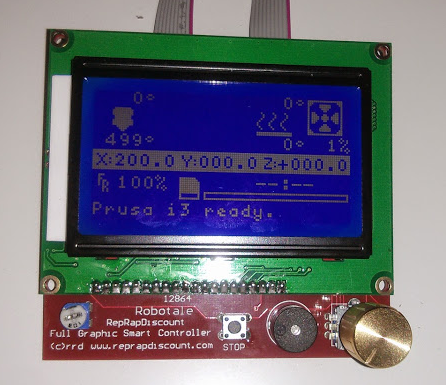
I first tried to add a 1.2K resistor and suddenly the screen started working(!) but it with too little contrast. Tried again with a 820 ohm resistor and it worked even better
Attaching pictures of the working display and the resistor mod.
Now, I will continue the build and hopefully end up with a working printer
Thanks for your help and good luck with getting your display working!
Best regards,
Henrik
Thanks for your reply and advice on how to connect the cables
Using the GND pins I managed to find out the correct plug directions but I still had nothing visible on the display (only blue background).
By looking at the serial console I could verify that the SD card reader was at least partially working by inserting a SD card in the reader and verify that "SD card ok" was written to the serial console.
Searching for contrast problem with the 12864 display helped my find this thread where a missing resistor seemed to improve the contrast.
I first tried to add a 1.2K resistor and suddenly the screen started working(!) but it with too little contrast. Tried again with a 820 ohm resistor and it worked even better
Attaching pictures of the working display and the resistor mod.
Now, I will continue the build and hopefully end up with a working printer
Thanks for your help and good luck with getting your display working!
Best regards,
Henrik
|
Re: Ramps 1.4 with graphical display: China LCD-Board Robotale 12864 layout wrong? February 13, 2015 06:16PM |
Registered: 9 years ago Posts: 49 |

|
Re: Ramps 1.4 with graphical display: China LCD-Board Robotale 12864 layout wrong? February 13, 2015 07:05PM |
Registered: 9 years ago Posts: 8 |
|
Re: Ramps 1.4 with graphical display: China LCD-Board Robotale 12864 layout wrong? February 15, 2015 03:15AM |
Registered: 9 years ago Posts: 2 |
Salve ragazzi !!! mi sono avventurato in una dura battaglia.Arduino mega 2560,ramps 1.4 display 12864 full graphic smart controller (tutto cinese)
sw di programmazione arduino 1.0.6 firmware marlin (provato quasi tutti quelli che ho trovato in giro,abilitando librerie,ecc.) si accende solo il display colore blu,premendo la manopola fa bip il bazzer fine.
. come posso verificare?? grazie .....
sw di programmazione arduino 1.0.6 firmware marlin (provato quasi tutti quelli che ho trovato in giro,abilitando librerie,ecc.) si accende solo il display colore blu,premendo la manopola fa bip il bazzer fine.
. come posso verificare?? grazie .....
|
Re: Ramps 1.4 with graphical display: China LCD-Board Robotale 12864 layout wrong? February 15, 2015 08:00AM |
Registered: 9 years ago Posts: 49 |
Hi!
You posted in the wrong forum - for the italian language forum area please see here: Reprap european forums
Best regards,
Chris
You posted in the wrong forum - for the italian language forum area please see here: Reprap european forums
Best regards,
Chris
|
Re: Ramps 1.4 with graphical display: China LCD-Board Robotale 12864 layout wrong? February 15, 2015 06:34PM |
Registered: 9 years ago Posts: 1 |
Ciao Camillo,
Non so se leggi inglese, ma per caso: Chris ti ha suggerito di fare la tua domanda al foro reprap che corrisponde all'Europa.
Comunque il tuo probblema si assomiglia a quello che Chris aveva originalmente. Se l'ho capito correttamente, la prima cosa che gli hanni suggerito é stato di verificare che il cavo di GND del display é collegato al GND dell' Arduino Mega. Sembra anche che manchi un resistore sul display (link)
Guarda gli attachment al post di HAL, oppure provaci a mettere il post di Hal su Google translate. Se non va, puoi provare a chiedere sul foro Europeo.
In bocca al lupo.
Edited 1 time(s). Last edit at 02/15/2015 06:35PM by jay_ar.
|
Re: Ramps 1.4 with graphical display: China LCD-Board Robotale 12864 layout wrong? March 04, 2015 12:19AM |
Registered: 9 years ago Posts: 3 |
|
Re: Ramps 1.4 with graphical display: China LCD-Board Robotale 12864 layout wrong? March 04, 2015 03:05AM |
Registered: 9 years ago Posts: 49 |
Hi embesys,
if your display contrast seems to be wrong you can easily check it with a normal multimeter. I only used my oscilloscope because I didn't know the reason of the failure and checked if the data streams are ok :-)
I have measured my contrast voltage again right now and it is 4,3V between the displays rightmost pin 1 (GND) and the third pin (V0 = display contrast voltage). When I get the display pcb I was able to set it between 0V and 1V only, which is wrong. To fix it I finally soldered a resistor of 390 Ohms between pin 2 (+5V) and pin 3 (V0). Now I can adjust the contrast voltage between 0V and 4,5V with the small trim resistor on the left bottom corner of the LCD board.
Good luck :-)
Chris
|
Re: Ramps 1.4 with graphical display: China LCD-Board Robotale 12864 layout wrong? April 10, 2015 03:27PM |
Registered: 9 years ago Posts: 13 |
|
Re: Ramps 1.4 with graphical display: China LCD-Board Robotale 12864 layout wrong? September 10, 2015 06:47PM |
Registered: 8 years ago Posts: 18 |
Sorry, only registered users may post in this forum.