modify ramps 1.4 to make it more reliable ?
Posted by migel_hrndz
|
modify ramps 1.4 to make it more reliable ? March 28, 2015 11:51AM |
Registered: 9 years ago Posts: 22 |
OK so recently my ramps board melted ( heated bed terminal) and so I started searching the internet on how I could prevent this from happening again...now I couldn't find a lot of things I could do
Do any of you guys know what are some mods that would make the ramps board more reliable ?
Do any of you guys know what are some mods that would make the ramps board more reliable ?
|
Re: modify ramps 1.4 to make it more reliable ? March 28, 2015 01:00PM |
Registered: 9 years ago Posts: 977 |
There is a very simple mod which I always recommend: to add an 80mm fan on a bracket on top of the RAMPS. That basically solves most heat related problems, and it's a $2 mod.
Another mod is to change the heatbed MOSFET for a IRLB873. That requires some soldering/unsoldering skills, but again it's a < $2 mod.
Finally, some people change the PTC fuses for fast car fuses (15A/6A respectively recommended). That is most easily done by bridging the traces with some thick copper wires and adding some fuse holders inline on the power supply leads.
Again, it requires some soldering/unsoldering skills and the cost is pretty low.
|
Re: modify ramps 1.4 to make it more reliable ? March 29, 2015 06:52AM |
Admin Registered: 13 years ago Posts: 6,998 |
|
Re: modify ramps 1.4 to make it more reliable ? March 29, 2015 07:09AM |
Registered: 9 years ago Posts: 977 |
Quote
Dust
also dont buy a $7 china ramps with 5amp connectors on the 11amp side!
Would you care to post a picture of "a $7 china ramps with 5amp connectors on the 11amp side"?
I think we should get through this myth that anything made in China is of bad quality. I only use made in China RAMPS boards and their quality is acceptable, no more, no less.

They come with screw terminals that - if properly tightened - will not overheat. Of course if you want to avoid any problems with the screw terminals you are always free to solder the wires for the heatbed directly to the RAMPS PCB.
Edited 1 time(s). Last edit at 03/29/2015 07:10AM by AndrewBCN.
|
Re: modify ramps 1.4 to make it more reliable ? March 30, 2015 09:51AM |
Registered: 10 years ago Posts: 869 |
The FCI connectors (the green ones) are only rated at 12 amps. Now that's the rated current. I run my heated bed at 15 amps without issue. But there's probably a reason why the connectors are rated at what they are.Quote
AndrewBCN
They come with screw terminals that - if properly tightened - will not overheat. Of course if you want to avoid any problems with the screw terminals you are always free to solder the wires for the heatbed directly to the RAMPS PCB.
|
Re: modify ramps 1.4 to make it more reliable ? March 30, 2015 11:33AM |
Registered: 9 years ago Posts: 286 |
Ive got a ramps board that i removed the cheap screw connectors and replaced with known good 16amp versions.
Ive also replaced the motor connector pins with proper locking connectors.
I havnt found anything small enough for the end stops or thermistor connectors.
Im also thinking of replacing the mosfets for higher grade ones.
To stop the power inputs scorching ive fitted crimped on very thin spade connectors that fit into the screw connectors.
This will be going on my next printer.
And so far its been cheaper than buying a new expensive one.
Gordon
Ive also replaced the motor connector pins with proper locking connectors.
I havnt found anything small enough for the end stops or thermistor connectors.
Im also thinking of replacing the mosfets for higher grade ones.

To stop the power inputs scorching ive fitted crimped on very thin spade connectors that fit into the screw connectors.

This will be going on my next printer.
And so far its been cheaper than buying a new expensive one.
Gordon
|
Re: modify ramps 1.4 to make it more reliable ? March 30, 2015 01:49PM |
Registered: 9 years ago Posts: 977 |
|
Re: modify ramps 1.4 to make it more reliable ? April 02, 2015 08:31PM |
Registered: 9 years ago Posts: 22 |
|
Re: modify ramps 1.4 to make it more reliable ? April 03, 2015 07:31AM |
Registered: 9 years ago Posts: 62 |
The most likely reason they get hot is an imperfect connection between the wire and connector
the same reason why they have trouble with the heater terminals on Ormerod 2 heatbeds, the nuts on the
connector posts work loose . you get resistance between the wire and post and heat is the result
Why not just solder the wires on to the board . That will more likely be a good cure to your problem and costs nothing to do
|
Re: modify ramps 1.4 to make it more reliable ? April 03, 2015 10:37AM |
Registered: 11 years ago Posts: 1,320 |
|
Re: modify ramps 1.4 to make it more reliable ? April 04, 2015 12:35AM |
Admin Registered: 13 years ago Posts: 6,998 |
at AndrewBCN
its not a myth
clasic eg for a cheap ramps....
Do you see the issue?
The owner tells me it did work fine after fixing this issue. But it very evident there is zero qc.
Edited 1 time(s). Last edit at 04/04/2015 12:36AM by Dust.
its not a myth
clasic eg for a cheap ramps....

Do you see the issue?
The owner tells me it did work fine after fixing this issue. But it very evident there is zero qc.
Edited 1 time(s). Last edit at 04/04/2015 12:36AM by Dust.
|
Re: modify ramps 1.4 to make it more reliable ? April 04, 2015 05:35AM |
Registered: 9 years ago Posts: 893 |
Quote
Dust
But it very evident there is zero qc.
Quality control? What's that?
I recently bought a Chinese-made RAMPS clone from a UK supplier (clearly a UK sales outlet for a Chinese distributor), and had all sorts of issues: it simply wouldn't talk to some of the stepper drivers. Disassembled everything and took a close look at the board with a 30X loupe - I found tiny blobs and hair-like traces of solder everywhere. Cleaned up all that I could find, but it still didn't work. Replaced it with a board that actually came directly from China (Geeetech) and that worked perfectly... apart from one issue I'm still chasing (but that's something I'll raise in a different topic).
|
Re: modify ramps 1.4 to make it more reliable ? April 04, 2015 10:24PM |
Registered: 9 years ago Posts: 977 |
Quote
Dust
at AndrewBCN
its not a myth
clasic eg for a cheap ramps....
Do you see the issue?
The owner tells me it did work fine after fixing this issue. But it very evident there is zero qc.
First you complained about the quality of the components, now you seem to have switched your argument to quality control in the assembly line...
OK, you are reporting one example of an incorrectly soldered RAMPS 1.4, I guess the young woman on the assembly line in China who earns $60 per month was tired, perhaps after working 6 hours straight just inserting connectors into PCBs.
That's one board out of possibly 1000 or 10000? So what does that give us, a 0.01% to 0.1% defect rate? Still quite low for a product that costs $7 shipped.
If you have ever visited a factory in China you'll notice that they indeed do have qc in all assembly lines, but even qc can fail.
Edited 1 time(s). Last edit at 04/04/2015 10:30PM by AndrewBCN.
|
Re: modify ramps 1.4 to make it more reliable ? April 05, 2015 06:13AM |
Admin Registered: 13 years ago Posts: 6,998 |
*snip*
Whats needed
Better connectors all over, locking and impossable to plug in backwards and over spec
Higher spec mosfets
Replace polyfuses with car type fuses
35v caps under pololu drivers so board will support 24v (some do this already)
Thicker tracks to all mosfets and their power connector to support more current.
Replace D1 with a 8-10volt voltage regulator (so no matter if you use 12v or 24v the mega still gets a nice safe 10v), and a jumper so you can still disable it
And If your really keen replace microstepping jumpers with a dip switches.
Edited 2 time(s). Last edit at 04/07/2015 10:08AM by VDX.
|
Re: modify ramps 1.4 to make it more reliable ? April 05, 2015 07:02AM |
Registered: 9 years ago Posts: 286 |
When i feel like splashing out and not beefing up the board myself thiscompany have a 24v arduino mega clone and a decent quality ramps board.
Bit more expensive but most of the works done for you.
If only it had locking conndctors for the motors, thermisters and endstops.
[ooznest.co.uk]
Taurino power is the 12-35v mega and the ramps board matches its spec.
No connection to company except ive bought a few bits and pieces from them.
Gordon
|
Re: modify ramps 1.4 to make it more reliable ? April 05, 2015 10:38AM |
Admin Registered: 13 years ago Posts: 6,998 |
|
Re: modify ramps 1.4 to make it more reliable ? April 06, 2015 09:29AM |
Registered: 10 years ago Posts: 869 |
And now your price just doubled plus you need to redesign the board to make room for your voltage regulator circuit. I'm not saying that your changes aren't desirable or not upgrades over the original design. Rather there is a reason why it's the most popular electronics choice. It's easy to manufacturer with commodity parts, it's proven even with it's flaws, and most likely most important, it's cheap.Quote
Dust
Whats needed
Better connectors all over, locking and impossable to plug in backwards and over spec
Higher spec mosfets
Replace polyfuses with car type fuses
35v caps under pololu drivers so board will support 24v (some do this already)
Thicker tracks to all mosfets and their power connector to support more current.
Replace D1 with a 8-10volt voltage regulator (so no matter if you use 12v or 24v the mega still gets a nice safe 10v), and a jumper so you can still disable it
And If your really keen replace microstepping jumpers with a dip switches.
|
Re: modify ramps 1.4 to make it more reliable ? April 06, 2015 11:07PM |
Registered: 9 years ago Posts: 4 |
Hello all,
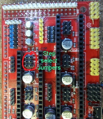
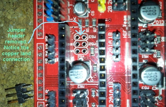
Could some of you folks do me a favor and check the continunity of your MS1 MS2 MS3 connections without the jumpers in? Mine were shorted without the jumpers in place. I'm hoping I have a fluke RAMPS 1.4 board - (from China) as I have ordered another Mega and RAMPS 1.4 from SainSmart. The short is actually a land that ties the 2 pins together making the jumpers useless - my board is fixed at the highest step rate the driver can do.
Edit: - Forgot to mention that the connection is under the jumper header. I had to unsolder the headers to find it.
Edited 1 time(s). Last edit at 04/06/2015 11:16PM by str8up.
|
Re: modify ramps 1.4 to make it more reliable ? April 07, 2015 06:03AM |
Admin Registered: 13 years ago Posts: 6,998 |
|
Re: modify ramps 1.4 to make it more reliable ? April 07, 2015 06:13AM |
Admin Registered: 13 years ago Posts: 6,998 |
|
Re: modify ramps 1.4 to make it more reliable ? April 07, 2015 12:25PM |
Registered: 9 years ago Posts: 4 |
Thanks Dust -
This isn't a case of sloppy solder bridging. This board has no indication of poor workmanship. The board worked just fine except the steps can not be changed. I'm going to try and attach some pictures. This post is FYI incase someone else is experiencing an issue with trying to change their step rates.
Later
|
Re: modify ramps 1.4 to make it more reliable ? April 07, 2015 01:42PM |
Registered: 9 years ago Posts: 977 |
Interesting. Yes, that is a fluke, the manufacturer of the PCB for some reason decided to do their own modified version of the PCB layout instead of a simple copy/paste from the original:
[reprap.org]
Note that most people won't ever notice if they have that problem or not as 1/16th microstepping with A4988 drivers seems to be the norm anyways.
It sure is a most puzzling fluke, and absolutely unexplainable unless one unsolders the jumper headers as you did.
[reprap.org]
Note that most people won't ever notice if they have that problem or not as 1/16th microstepping with A4988 drivers seems to be the norm anyways.
It sure is a most puzzling fluke, and absolutely unexplainable unless one unsolders the jumper headers as you did.
|
Re: modify ramps 1.4 to make it more reliable ? April 07, 2015 03:39PM |
Registered: 9 years ago Posts: 4 |
AndrewBCN
You are right about most people may not notice this and for the most part it will never be a problem. For me, if I buy something that has options - I want the options. The way I caught this was removing the jumper and measuring across the pins - should have read open. The reason I was trying different step rates was that I have older 0.9 deg. steppers and was trying to get a quieter operation. I had also upgraded the Pololu drivers from A4988 to DRV8825 which went to 32 micro steps.
You are right about most people may not notice this and for the most part it will never be a problem. For me, if I buy something that has options - I want the options. The way I caught this was removing the jumper and measuring across the pins - should have read open. The reason I was trying different step rates was that I have older 0.9 deg. steppers and was trying to get a quieter operation. I had also upgraded the Pololu drivers from A4988 to DRV8825 which went to 32 micro steps.
|
Re: modify ramps 1.4 to make it more reliable ? April 07, 2015 04:17PM |
Registered: 9 years ago Posts: 977 |
Quote
str8up
AndrewBCN
You are right about most people may not notice this and for the most part it will never be a problem. For me, if I buy something that has options - I want the options. The way I caught this was removing the jumper and measuring across the pins - should have read open. The reason I was trying different step rates was that I have older 0.9 deg. steppers and was trying to get a quieter operation. I had also upgraded the Pololu drivers from A4988 to DRV8825 which went to 32 micro steps.
I see, you had good reasons to try 1/16 microstepping and it must have been really puzzling when you removed the jumpers to configure the DRV8825's for 1/16th and nothing happened. I confess I would never have thought of checking under the headers!
I am trying to think of a possible explanation for the manufacturer of the PCB to have added these shorting islands but in the end I just think it is an error by the PCB (re)designer who just did not understand the purpose of these jumpers. Sometimes people have a hard time even doing a straightforward copy-and-paste...
|
Re: modify ramps 1.4 to make it more reliable ? April 07, 2015 05:39PM |
Registered: 10 years ago Posts: 869 |
If you go with the idea that everyone would want 1/16 microstepping, bridging the pins with the trace would be cheaper than having to install header pins and supply jumpers. As the copper is removed during etching, there is zero additional cost to leave the trace but then it forces 1/16 microstepping. It's possible Board House A produced a kabillion boards for Assembler A with the trace knowing they were 1/16th only, but then sold a surplus supply to Assembler B who didn't know it.Quote
AndrewBCN
I am trying to think of a possible explanation for the manufacturer of the PCB to have added these shorting islands but in the end I just think it is an error by the PCB (re)designer who just did not understand the purpose of these jumpers. Sometimes people have a hard time even doing a straightforward copy-and-paste...
|
Re: modify ramps 1.4 to make it more reliable ? April 07, 2015 08:11PM |
Registered: 9 years ago Posts: 977 |
Quote
cdru
If you go with the idea that everyone would want 1/16 microstepping, bridging the pins with the trace would be cheaper than having to install header pins and supply jumpers. As the copper is removed during etching, there is zero additional cost to leave the trace but then it forces 1/16 microstepping. It's possible Board House A produced a kabillion boards for Assembler A with the trace knowing they were 1/16th only, but then sold a surplus supply to Assembler B who didn't know it.Quote
AndrewBCN
I am trying to think of a possible explanation for the manufacturer of the PCB to have added these shorting islands but in the end I just think it is an error by the PCB (re)designer who just did not understand the purpose of these jumpers. Sometimes people have a hard time even doing a straightforward copy-and-paste...
That figures, indeed. Either Assembler B wasn't informed of the shorting islands and just didn't check the PCBs, or they were informed of the islands but did not understand what they were for and soldered the (now useless) headers over them.
|
Re: modify ramps 1.4 to make it more reliable ? May 29, 2015 01:59AM |
Registered: 10 years ago Posts: 11 |
I had a friend order a RAMPS 1.4 from Geeetech. Instead of a 1K ohm resistor for the X-axis, it had a 100 ohm resistor. And T1 had a 100Kohm resistor, instead of 4.7K ohm resistor. The other resistors had terrible tolerances.
I buy all of my RAMPS from K Bell on eBay
Always high quality, zero problems. They are in St Louis....I am in Arkansas, which the short distance also makes them more appealing to me.
For mods...I always remove the stock stepper connectors and replace them with salvaged connectors from floppy drives. For the wires going into the power connectors and the connectors for pins 8-10, I solder the ends of the wire to prevent stray wires from visiting the adjacent terminals. Somewhere on here, a guy said a stray wire almost burned his house down. After soldering, the use pliers to gently compress the ends flat and trim then to fit snugly into the terminals. But, properly sized spade connectors (with heat shrink as pictured above) would be ideal!!!
And for micro-stepping, do not forget you loose torque. I think it was nopehead (HydraRaptor) that wrote a blog with the details.
Edited 1 time(s). Last edit at 05/29/2015 02:07AM by nitewing76.
|
Re: modify ramps 1.4 to make it more reliable ? May 29, 2015 06:54AM |
Registered: 9 years ago Posts: 977 |
Quote
nitewing76
...
And for micro-stepping, do not forget you loose torque. I think it was nopehead (HydraRaptor) that wrote a blog with the details.
You do not lose torque with microstepping, you just get more silent operation and less vibrations. This is explained here: [www.micromo.com]
What it really boils down to for RepRap builders with a RAMPS 1.4 is that you should use 1/16 microstepping (or 1/32 if available).
|
Re: modify ramps 1.4 to make it more reliable ? October 19, 2015 04:08AM |
Registered: 11 years ago Posts: 423 |
Quote
str8up
Thanks Dust -
This isn't a case of sloppy solder bridging. This board has no indication of poor workmanship. The board worked just fine except the steps can not be changed. I'm going to try and attach some pictures. This post is FYI incase someone else is experiencing an issue with trying to change their step rates.
Later
Nice find, thank you for sharing. I'm facing the same issue. My Ramps is labeld RamSP14.A (yes: RAMSP instead o RAMPS
 ) and I wonder if is it possible to fix the microstepping issue simply cutting the bridges. Have you tried it or found any other solution?
Alfredo
Q*Bot Delta Printer: [forums.reprap.org]
Q*Extruder V2: [forums.reprap.org]
|
Re: modify ramps 1.4 to make it more reliable ? October 20, 2015 05:44AM |
Admin Registered: 13 years ago Posts: 6,998 |

Sorry, only registered users may post in this forum.