Wiring proximity induction probe
Posted by Son
|
Wiring proximity induction probe April 02, 2015 06:34AM |
Registered: 9 years ago Posts: 10 |
Hello everybody!
I've been creating my printer for like a month and time has come to wire it. The only problem I have is connecting induction probe...
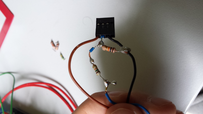
I have done this
and that's how it looks like:
Now I have no idea where should I wire it to my ramps 1.4
The model is LJ12A3-4-Z/BX NPN DC 6-36 V NO
Big thanks to anyone who will help!
PS: I have really little knowledge about pin nomenclature, so actually visual pointing finger at schematics would be the best possibility
I've been creating my printer for like a month and time has come to wire it. The only problem I have is connecting induction probe...
I have done this
and that's how it looks like:
Now I have no idea where should I wire it to my ramps 1.4

The model is LJ12A3-4-Z/BX NPN DC 6-36 V NO
Big thanks to anyone who will help!
PS: I have really little knowledge about pin nomenclature, so actually visual pointing finger at schematics would be the best possibility

|
Re: Wiring proximity induction probe April 02, 2015 09:55AM |
Registered: 10 years ago Posts: 869 |
If you're lucky, your sensor will work at 5V. If it does, you just need to wire the sensor so that the brown wire goes to the + terminal on the RAMPS board, Blue goes to -, and Black goes to S[ignal]. Resistors aren't necessary with your sensor when it runs at 5V. Be sure to enable the pull up resistor for the Z-min (or whatever endstop pin you use) to hold the pin high otherwise it will float and could lead to erratic operation.
|
Re: Wiring proximity induction probe April 02, 2015 11:13AM |
Registered: 9 years ago Posts: 10 |
|
Re: Wiring proximity induction probe April 02, 2015 11:46AM |
Registered: 10 years ago Posts: 869 |
Well wired like that it's not going to work either since the ramps connector is still supplying it with only 5V plus your resistors are completely wrong if not furthering your problem. If you are going to use 12V, you'll have to steal it from elsewhere on the board as the endstop connector is 5V. Even if you take the 12V elsehwere, you still don't need any resistors. The sensor just acts as a switch grounding the arduino's pin. The 12V line doesn't feed the signal wire with a NPN sensor. It would if you had a PNP sensor which is likely where you got that schematic from. I found that same picture on other forums for a lj12a3-4-z/by sensor which is a PNP. Double check to make sure you have a lj12a3-4-z/bx.
|
Re: Wiring proximity induction probe April 02, 2015 11:59AM |
Registered: 9 years ago Posts: 10 |
|
Re: Wiring proximity induction probe April 02, 2015 04:19PM |
Registered: 10 years ago Posts: 869 |
|
Re: Wiring proximity induction probe April 03, 2015 04:11PM |
Registered: 9 years ago Posts: 10 |
Not sure if I'm retard or probe is just broken or badly connected
Cables are this way and there's no response.
Here's mine Configuration.h from Marlin, maybe something with code is wrong...
[pastebin.com]
Edited 1 time(s). Last edit at 04/03/2015 04:18PM by Son.
Cables are this way and there's no response.
Here's mine Configuration.h from Marlin, maybe something with code is wrong...
[pastebin.com]
Edited 1 time(s). Last edit at 04/03/2015 04:18PM by Son.
|
Re: Wiring proximity induction probe April 03, 2015 09:01PM |
Registered: 10 years ago Posts: 869 |
Your wiring appears to be correct. You might double check to make sure you have 12V from where you have the brown dot to where you have the blue dot...just to make sure there isn't a bad solder joint.
Move the probe so that it shouldn't be tripped. Enter the command M119 and what is returned for z-min? Move the probe so that it should be tripped. Run M119 again. It should be different. If there is no change, unplug the probe from Z-min and install a jumper between the blue and black dotted pins. Run M119 again and see if there is a change. If there's still no change, then your z-min is probably fried. If there is a change, then your sensor or your wiring is bad.
It's not hard to test the sensor away from the RAMPS board. Hook up 12V to the brown wire, ground to the blue. Then get a 12V fan, light bulb, etc...some other light load and wire it's - connection to the black wire and it's + connection also to the 12V. The probe should keep it off until it is tripped and then turn on.
You did remove those resistors you soldered to the wires in your original post, right?
|
Wiring proximity induction probe April 04, 2015 06:08AM |
Registered: 9 years ago Posts: 10 |
I'm not sure how do I check if bad solder joint is "bad" so I'm posting pictures of it.
Z-min is always open, as M119 says (X & Y endstops work well) - When triggered or not, with jumper on black & blue pin (where brown cable is still on it's correct place) or just with cables connected.
I will test probe like you said and will update.
Do I have to buy new RAMPS if Z-Min is fried?
Thanks for keep helping me
EDIT: Probe works with circuit outside of RAMPS.
EDIT2: I found that topic [forums.reprap.org] and guy put 12VDC onto the Z MIN pin on the Polouno board and fried it. Isn't it what I was doing? *sorry for stupid question, I'm not good at that stuff * Also there's advice for reasigning pin, should I follow it?
Edited 2 time(s). Last edit at 04/04/2015 07:35AM by Son.
By this you mean "triggered", right?Quote
cdru
Move the probe so that it shouldn't be tripped.
Yes, I did. Only pure cables left.Quote
cdru
You did remove those resistors[...]
Z-min is always open, as M119 says (X & Y endstops work well) - When triggered or not, with jumper on black & blue pin (where brown cable is still on it's correct place) or just with cables connected.
I will test probe like you said and will update.
Do I have to buy new RAMPS if Z-Min is fried?
Thanks for keep helping me

EDIT: Probe works with circuit outside of RAMPS.
EDIT2: I found that topic [forums.reprap.org] and guy put 12VDC onto the Z MIN pin on the Polouno board and fried it. Isn't it what I was doing? *sorry for stupid question, I'm not good at that stuff
 * Also there's advice for reasigning pin, should I follow it?
Edited 2 time(s). Last edit at 04/04/2015 07:35AM by Son.
|
Re: Wiring proximity induction probe April 06, 2015 09:59AM |
Registered: 10 years ago Posts: 869 |
It's easiest with a multimeter that has a tone for continuity, but you can use one that shows just the resistance too. Hold one end of the lead on the pin that leads to the Mega board. Touch the other probe to the other end of the circuit. You should hear a tone or have close to 0 ohms resistance. Touch the other endstop pins around to make sure you don't have continuity to any of those pins. If you do, you have a short somewhere.Quote
Son
I'm not sure how do I check if bad solder joint is "bad" so I'm posting pictures of it.
YesQuote
By this you mean "triggered", right?
With the jumper not making a difference, then I would say that pin is no longer working.Quote
Z-min is always open, as M119 says (X & Y endstops work well) - When triggered or not, with jumper on black & blue pin (where brown cable is still on it's correct place) or just with cables connected.
Probably not. You are probably only using the min or max pins for the X and Y axis, so the other ones could be used. Look in your pins.h file and swap the Z_Min_Pin with one of the end stops you aren't currently using.Quote
Do I have to buy new RAMPS if Z-Min is fried?
The schematic that you were originally using was for a PNP sensor and if you had one that was hooked up to 12V source, yes, it would have been feeding 12V to the Arduino. However it sounds like you were always using a NPN sensor so it wouldn't have been feeding 12V to the signal pin...plus if you were always using + from the endstop headers it would have only have been 5V. With your resistors wired how you have them, I don't think your miswiring, as photographed, would have fired the z-min pin. However if you tried different things it's possible you inadvertently friend it.Quote
EDIT2: I found that topic [forums.reprap.org] and guy put 12VDC onto the Z MIN pin on the Polouno board and fried it. Isn't it what I was doing?
|
Re: Wiring proximity induction probe April 07, 2015 05:01PM |
Registered: 9 years ago Posts: 10 |
Quote
cdru
With the jumper not making a difference, then I would say that pin is no longer working.
Actually, I moved Y endstop to Z pin and it worked perfectly. No idea why probe doesn't respond on that pin...
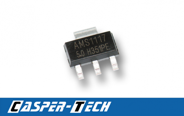
Also I detonated this little thingy (by connecting probe like normal endstop - yeah I know, irresponsibly),
but it didn't have use anyway.
So my only idea is it try out other pins by editing pins.h (actually that file ...RAMPS_13.h)
That's really annoying - probe works, pins are okay for endstops, wtf?
|
Re: Wiring proximity induction probe February 02, 2016 07:10PM |
Registered: 8 years ago Posts: 22 |
|
Re: Wiring proximity induction probe February 21, 2017 09:10AM |
Registered: 9 years ago Posts: 73 |
Sorry, only registered users may post in this forum.

