RAMPS 1.4.2 fork: RD3D v1.0 (6 steppers, 24v, Due)
Posted by lkcl
|
RAMPS 1.4.2 fork: RD3D v1.0 (6 steppers, 24v, Due) September 14, 2017 02:31PM |
Registered: 8 years ago Posts: 776 |
[reprap.org]
it may seem strange to create another RAMPS fork, i have however been looking for something in Taiwan / Hong Kong / China (i am currently in TW) that isn't GPL violating, that's 32-bit, that isn't MKS Base so won't fall to bits, that isn't the same amount of money that you can buy an entire 3D printer for in China (yes, you can get a 3D printer for $USD 150 which is the same amount as a DuetNG!)... and it's just not working out.
this may come as a bit of a shock to people but in the huaqiang road market in the futian district of shenzhen, a RAMPS 1.4 board can be bought for around $USD 3.50
i'll say that again in case it's not clear.
a one-off (QTY 1) fully-functioning, assembled RAMPS 1.4 board can be bought in the markets in Shenzhen for THREE and a half United States Dollars.
by the time you have added an ATMEGA 2560 clone and four A4988-compatible polulu boards that's up to an amazing $USD 16 for a full kit, and it's highly likely that the people selling the kits at $USD 16 are massively overcharging by at least 50%.
thus, when i see boards available for sale in the USA and Europe, and they're $USD 50, 70, 80, 100, 120, 150 there's a sort-of.... mental rebellion going on that refuses to let me pay out that much money (plus customs duty, plus import tax, plus tax, plus tax on shipping, plus customs duty on shipping, plus customs duty on tax on shipping, plus tax on tax, plus tax on customs duty on tax on tax...) and you just know the components started out in china anyway.
then there's the endemic GPL firmware violations which piss everybody off.
then there's the *hardware* design files copyright violations...
the last straw though was, after tracking down the RADDS board and having spent a long time evaluating it and liking it very much because it has good support for RepRapFirmware, i went looking for the CAD files only to find that it is a proprietary design with a non-free license.
that was yesterday.
so i've spent the past 24 hours hacking RAMPS 1.4.2, using the RADDS schematic as a guide on how to do a Due Shield, to add in a 6th Stepper, a MicroSD Card, a 24v-tolerant LDO to supply the Due's main power, cut out 50% of the AUX connectors which freed up a large amount of pins so that the tracks no longer needed to go right across the board, and generally hugely cleaned up the design.
the reason for supporting the Due is because i want to port RepRapFirmware to this board, i need much faster processing power than a 2560 can handle. the reason for 6 steppers is so that i can do Triple Z leadscrews (for auto bed levelling) plus X, Y and Extruder. the MicroSD card is added so that RepRapFirmware has somewhere to store its configuration files. i've left AUX3 on because i want to be able to connect an SPI-ETH (ENC28J60) so that the RepRapFirmware web interface will work with minimum effort.
in the meantime, before working on RepRapFirmware, Marlin will be the immediate up-and-running firmware.
the extra components needed should cost a whole $0.50 extra, and definitely no more than $1. MicroSD push-push sockets are around $0.20, i've taken off several pin headers and the UA78M LDO will not be hugely costly (well under $0.50).
if anybody is interested i'm going to be getting 10 samples made up very very soon (i have a deadline for Shenzhen Maker Faire, which is on the 10th November). if anyone would like to review, commentt or has any suggestions, i'd love to hear them. i apologise in advance that i have to move quite quickly.
source code files (GPLv3) all referenced at the link at the top.
l.
|
Re: RAMPS 1.4.2 fork: RD3D v1.0 (6 steppers, 24v, Due) September 14, 2017 04:35PM |
Registered: 10 years ago Posts: 14,672 |
Just a couple of warnings/suggestions:
- I'm fairly sure that the Arduino Due can't support the HSMCI interface to the SD card, it only supports the much slower SPI interface. Without HSMCI you won't get high-speed upload to the SD card over the network.
- I looked at the ENC28J60 when designing the Duet Ethernet and rejected it due to insufficient buffer memory to achieve satisfactory performance. We went with the W5500 instead.
I guess you can ignore these issues if you don't care about fast gcode file uploading to the SD card; but most Duet users care a great deal about upload speed because they don't use a USB connection, just a network connection.
Large delta printer [miscsolutions.wordpress.com], E3D tool changer, Robotdigg SCARA printer, Crane Quad and Ormerod
Disclosure: I design Duet electronics and work on RepRapFirmware, [duet3d.com].
|
Re: RAMPS 1.4.2 fork: RD3D v1.0 (6 steppers, 24v, Due) September 15, 2017 02:02AM |
Registered: 8 years ago Posts: 5,232 |
|
Re: RAMPS 1.4.2 fork: RD3D v1.0 (6 steppers, 24v, Due) September 15, 2017 02:46AM |
Registered: 8 years ago Posts: 776 |
Quote
o_lampe
Which Marlin version will you run on the Due? Marlin4Due seemed to be in hibernation mode for a while...
i'll see how that goes. whatever i use it's a new board port, a totally new set of pins will be needed. a standard atmega 2560 should actually work, even without any level-conversion: i'll see how it goes. ENC28J60 (SPI-ETH from Microchip) is actually a 3.3v part that happens to be 5V tolerant. i beefed up the 3v3 power rail so that there won't be any voltage drop when supplying the max 180mA required power for it.
|
Re: RAMPS 1.4.2 fork: RD3D v1.0 (6 steppers, 24v, Due) September 15, 2017 02:52AM |
Registered: 8 years ago Posts: 776 |
Quote
dc42
Just a couple of warnings/suggestions:
always appreciated
Quote
- I'm fairly sure that the Arduino Due can't support the HSMCI interface to the SD card, it only supports the much slower SPI interface. Without HSMCI you won't get high-speed upload to the SD card over the network.
yeah i uploaded 1.19+6 just recently and was blown away by the microsd upload speed! no i'm not so concerned about speed, more about cost. remember i need to get 10 3D printers made up.
Quote
- I looked at the ENC28J60 when designing the Duet Ethernet and rejected it due to insufficient buffer memory to achieve satisfactory performance. We went with the W5500 instead.
interesting, thanks for the tip. just looking it up.... datasheet says it's 3.3v with 5v tolerance.... W5500 shields are $8 on ebay so that's a good sign. i'll make a note of that as i feel i'd be happier with RepRapFirmware. will start with Marlin as that's going to be needed too. best to support both, really.
Quote
I guess you can ignore these issues if you don't care about fast gcode file uploading to the SD card; but most Duet users care a great deal about upload speed because they don't use a USB connection, just a network connection.
yehyeh, which is more reliable, no power-spiking. my laptop actually dies rather than the USB-UART, it has an EMI / power fault *sigh*
 anyway - really appreciate your advice dc42.
|
Re: RAMPS 1.4.2 fork: RD3D v1.0 (6 steppers, 24v, Due) September 15, 2017 04:01AM |
Admin Registered: 13 years ago Posts: 6,998 |
If you do go Due, you might also want to look at SMART_RAMPS
It already exists.. or just for info...
Also there is a good thread on modifying standard ramps for due... [forums.reprap.org]
Edited 1 time(s). Last edit at 09/15/2017 04:30AM by Dust.
It already exists.. or just for info...
Also there is a good thread on modifying standard ramps for due... [forums.reprap.org]
Edited 1 time(s). Last edit at 09/15/2017 04:30AM by Dust.
|
Re: RAMPS 1.4.2 fork: RD3D v1.0 (6 steppers, 24v, Due) September 15, 2017 04:08AM |
Admin Registered: 13 years ago Posts: 6,998 |
Quote
dc42
- I'm fairly sure that the Arduino Due can't support the HSMCI interface to the SD card, it only supports the much slower SPI interface. Without HSMCI you won't get high-speed upload to the SD card over the network.
According to [www.testcor.ca]
All the HSMCI pins are mapped and broken out... so if there is an issue its software...
I also see libraries eg [github.com]
(no idea if it works though)
|
Re: RAMPS 1.4.2 fork: RD3D v1.0 (6 steppers, 24v, Due) September 15, 2017 04:51AM |
Registered: 8 years ago Posts: 776 |
Quote
Dust
Quote
dc42
- I'm fairly sure that the Arduino Due can't support the HSMCI interface to the SD card, it only supports the much slower SPI interface. Without HSMCI you won't get high-speed upload to the SD card over the network.
According to [www.testcor.ca]
All the HSMCI pins are mapped and broken out... so if there is an issue its software...
I also see libraries eg [github.com]
(no idea if it works though)
mmm dc42 (with the duets) has a bit of an advantage, here: on-board ATSAM3 (SAM4 for NG), so these kinds of decisions can be made and stuck with, expand the PCB size, redesign things. i'm.... on a tight deadline for this one, i want to get first prototype PCBs plus components back in a week and assemble them here at my flat in TW. i'd also really like to have dual 2560 and Due compatibility, as there will be some people who significantly want to save cost.
if i were to add those extra pins for the HSMCI, it's not guaranteed to work for the 2560, and i may have to expand the PCB size to fit (which i'm not keen on doing). i've expanded the width to 2.5in already from the original... 2.2in i think it is. it would be a delay of another day or two. let me think about it for a 2nd Due-only version ok
 once i have one version (slow or not) then a faster version can be done, and at least refer people to the older one if they want to use a 2560. and thank you for making me aware that there's a library, that's really useful.
|
Re: RAMPS 1.4.2 fork: RD3D v1.0 (6 steppers, 24v, Due) September 15, 2017 06:01AM |
Registered: 8 years ago Posts: 776 |
Quote
Dust
If you do go Due, you might also want to look at SMART_RAMPS
It already exists.. or just for info...
appreciated.... strange: they supply external VCC (5V) or maybe it's a jumper so you can change the supply voltage.... yeh it has the standard 5 driver sockets, i need 6 (triple lead screws, X, Y, Extruder)
ah. interesting. valuable. that led me to this (hello again dc42) [forums.reprap.org]
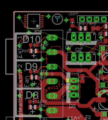
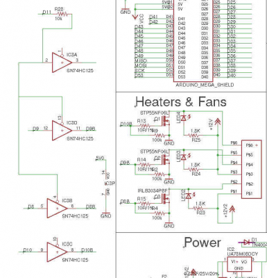
so i checked the datasheet on IRLB3034PBF and arse damnit yes the RDSon is 4.5v. frick. ok so luckily i moved all the LEDs out of the top left corner, to put them in front of each of their respective connectors:
what that means is that there's room in that top left corner for a TSSOP-14, and, by a happy coincidence it's very close to not just the MOSFETs but also D8, D9 and D10. so that's good news. so i'll use a SN74HC125 in TSSOP-14 packaging.
oh, one thing that might be nice: wiring an isolate GPIO to the MOSFETs. the buffers can be switched off so might as well.
the drivers... not being able to be powered properly off of 3.3v.... i have a suspicion that the track width normally used on a standard RAMPS (because of the tiny distance between pins, you can only squeeze a 12mil trace between them) simply aren't able to handle the current. *sigh* i really should deal with that. i'll route a 32mil trace mostly left-right as the driver pins are extremely tight together. argh will have to move the 6th driver to the right a bit, oh well.
|
Re: RAMPS 1.4.2 fork: RD3D v1.0 (6 steppers, 24v, Due) September 15, 2017 06:42AM |
Admin Registered: 13 years ago Posts: 6,998 |
|
Re: RAMPS 1.4.2 fork: RD3D v1.0 (6 steppers, 24v, Due) September 15, 2017 07:57AM |
Registered: 8 years ago Posts: 776 |
Quote
Dust
While you at it, please route D7 somewhere, it bugs me that its just abandoned on ramps
i'll most likely use it as a "default powered off" MOSFETs line: it's right there so why not. i believe i can just put in a pull-up resistor (10k) onto D7, that should bring it lo HIGH, that in the SN74HC125 OE# terminology will make the outputs all tri-state. with all outputs tri-state the resistors on the gates will drain down to GND. D7 to LOW will pull all OE# HIGH, that will enable all the buffers.
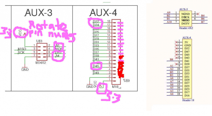
btw D22 is also strangely disconnected. what i've done is move almost everything possible off of the 2x18-pin connector, left all of the right-most pins connected straight to the AUX4, however i am deliberately not using any of the left-hand 2x18 row of pins with the sole exception of SPI.
[edit: correction: i'm already using D7 for E0-EN as i re-routed pretty much everything so that it does straight up or down to where it's needed - no messing about routing stuff all over the shop. i meant D11 i will use for the tri-state buffer control]
Edited 1 time(s). Last edit at 09/15/2017 08:01AM by lkcl.
|
Re: RAMPS 1.4.2 fork: RD3D v1.0 (6 steppers, 24v, Due) September 15, 2017 09:48AM |
Registered: 8 years ago Posts: 776 |
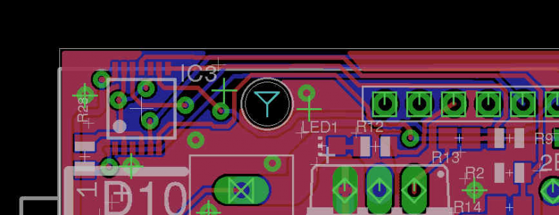
ok so added the SN74HC125, quite straightforward.
the routing's a mess (gahh! cramped 2-layer PCBs! eagle!! argh!) - normally i would clean it up but it's entirely by hand, there's no push-and-shove in eagle.... *sigh*...
i've expanded the PCB size along the top long side by about 0.2in to get the tracks in at the top. nice thing about that is, i can put some GND vias along the rest of the board edge. i'm kinda amazed that there's no GNDing vias *at all* in the RAMPS 1.4 - i appreciate that there's a lot of through-hole GND pins, but even so... anyway.
i'd like to be able to move that screw-hole down, but... it's done now.
|
Re: RAMPS 1.4.2 fork: RD3D v1.0 (6 steppers, 24v, Due) September 17, 2017 06:57AM |
Registered: 8 years ago Posts: 776 |
ok i couldn't stand the mess after 24 hours, so i turned the buffer IC round, which allowed me to do a cleanup. allsooo...
this is screaming at me "add another MOSFET, add another MOSFET!"
 the buffer IC is a quad, so that's not a problem. the expansion of the depth of the PCB needed to include the micro-sd card in the bottom right corner also means that there's space to move the entire lot of DC power input, diodes, fuses, 3 existing MOSFETs and the D8-D10 connectors down by about 5mm or so: that should be plenty to get an 8-pin block in for D8-D11 instead.
the only thing is... i'm really pushing it for time and it would take 24-36 hours to comfortably move so many tracks, plus the fuses, diode and basically the entire bottom left corner layout would need to be reorganised. so.... much as i really want to do it i feel this has to be for a revision 1.1
monday the factories are open so i will be asking a couple of them to make this 2-layer PCB. let's see what happens!
|
Re: RAMPS 1.4.2 fork: RD3D v1.0 (6 steppers, 24v, Due) September 17, 2017 12:39PM |
Registered: 8 years ago Posts: 5,232 |
|
Re: RAMPS 1.4.2 fork: RD3D v1.0 (6 steppers, 24v, Due) September 17, 2017 04:00PM |
Registered: 8 years ago Posts: 776 |
Quote
o_lampe
Just to put more pressure on you: You could save a lot of MOSFET terminal space by providing one big common terminal for V+.
ah: that would (i think) mean putting multiple wires into one terminal block, which is very risky and quite difficult. and also a hell of a lot of currrent. better to have multiple wires. also two separate fuses.
|
Re: RAMPS 1.4.2 fork: RD3D v1.0 (6 steppers, 24v, Due) September 17, 2017 07:43PM |
Registered: 8 years ago Posts: 776 |
i just... couldn't leave it alone, could i. kept going, sort-of not-really-slept a couple of times for 45 minutes... but got it done. the protection diode i moved out the way (90 degrees), then moved the fuses down a bit. shuffled the power block down... added 2 extra terminals to what used to be a 6-pin Molex... managed to get it all wired up. didn't move the MOSFETs, added the extra one, but i had to redo all the power planes.
initially i made them so big that i started getting concerned about having cut too much out of the GND planes! so i had to carefully look to see how much copper was left for GND and start cutting back on the power. i think there may be a way to reorganise the LEDs and the MOSFET switching lines to get better connectivity. don't really want to go to 4-layer although it would be a much better board....
the rectangles for the copper pour are a mess, as are a lot of the tracks for the buffer. i *really* miss the features of PADS, i am genuinely horrified at what people have to put up with in eagle. i'm slowly getting used to it.
anyway, this is done in time. whew

|
Re: RAMPS 1.4.2 fork: RD3D v1.0 (6 steppers, 24v, Due) September 17, 2017 07:53PM |
Admin Registered: 13 years ago Posts: 6,998 |
since you have moved d1 out from under the pololu, how about replacing it with a 7809 TO-220 package
would make it much easier to run the ramps on 24v and would reduce the load on the mega/due voltage regulator
Presuming its still going to vin...
Edited 1 time(s). Last edit at 09/17/2017 07:56PM by Dust.
would make it much easier to run the ramps on 24v and would reduce the load on the mega/due voltage regulator
Presuming its still going to vin...
Edited 1 time(s). Last edit at 09/17/2017 07:56PM by Dust.
|
Re: RAMPS 1.4.2 fork: RD3D v1.0 (6 steppers, 24v, Due) September 17, 2017 08:48PM |
Registered: 9 years ago Posts: 978 |
Quote
lkcl
i'd also really like to have dual 2560 and Due compatibility, as there will be some people who significantly want to save cost.
Don't bother.... People who care about the $6 difference in cost between a Due and a 2560 won't buy your board anyway... they'll buy a Mega and a RAMPS 1.4.
|
Re: RAMPS 1.4.2 fork: RD3D v1.0 (6 steppers, 24v, Due) September 18, 2017 12:55AM |
Registered: 8 years ago Posts: 776 |
Quote
Dust
since you have moved d1 out from under the pololu, how about replacing it with a 7809 TO-220 package
would make it much easier to run the ramps on 24v and would reduce the load on the mega/due voltage regulator
Presuming its still going to vin...
ha! that would be a good idea - i hadn't got into actual component review, this is really helpful to prompt me to think about it. a standard diode... yeah it's dropping 0.7v... that means the 8v would come out at around 7.3v... still in spec for the mega/due. yes it's going to Vin, and it's from the output of the UA78M not from the main power input. it's there i presume to stop a potential problem where people plug in a 12v DC jack into the arduino / due.
so, point being, the diode only ever sees 8v on its input.
that through-hole diode's pretty big - it shouldn't have a huge amount of resistance... i chose a SOT223 package because they're big and chunky and the tab acts as a heat spreader. it can deliver 500mA which *should* be enough... i'll have to find another part otherwise (board's been sent off to manufacturing) and maybe do some wiring on the first prototypes if i got that wrong, oh well.
hmmm... the 3.3v supply from the arduino / due is only 200mA... hmm.... running a microsd card could easily eat most of that... luckily it can only be run very slowly.
looking at the A4988 datasheet, "motor supply current (on) 4mA, logic supply current (on) 8mA) so 12mA total, 6 steppers means 72mA.
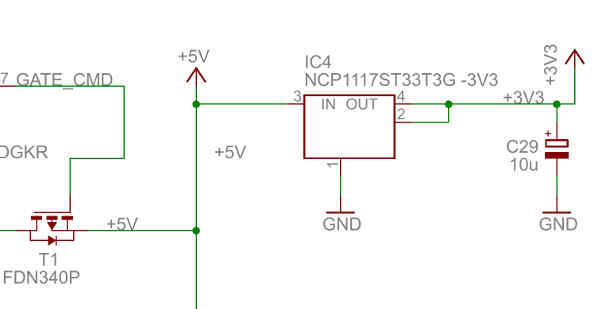
.... hmm time to look at the due datasheet. ah! it uses an NCP1117 which is a 1A output!
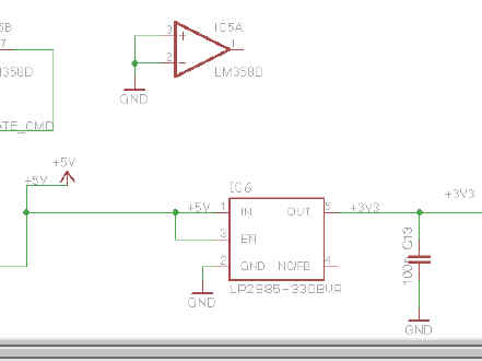
so that's not a problem. what about the arduino atmega 2560? let's check that.... argh it's an LP2985:
that's only 150mA! wtf!! so yeah no prizes there - that's going to be very tight, it should be fine for running the steppers, and also with the quad buffers no problem running the MOSFETs, and all the electronics... but running the MicroSD card and considering running a W5500 ethernet... no chance!! the W5500 takes 130mA on its own!
so... due should be fine, 2560 will be limited functionality but should work. we'll find out, ehn?

darn it i was looking for something like that NCP1117 oh well gerbers are off to the factory, i'll order some NCP1117s in 12v and wire them on.
|
Re: RAMPS 1.4.2 fork: RD3D v1.0 (6 steppers, 24v, Due) September 18, 2017 01:05AM |
Registered: 8 years ago Posts: 776 |
Quote
frankvdh
Quote
lkcl
i'd also really like to have dual 2560 and Due compatibility, as there will be some people who significantly want to save cost.
Don't bother.... People who care about the $6 difference in cost between a Due and a 2560 won't buy your board anyway... they'll buy a Mega and a RAMPS 1.4.
hehe, yeah - it looks like i made some mistakes where it'll be of limited functionality anyway. only a 150mA LDO for the 3.3v on the uno, dang.
*rueful*... i recommended to my friend to buy a Mega and a RAMPS 1.4... admittedly they're china-supplied ($USD 3.50 for the RAMPS 1.4.... daaamn!) ... unfortunately all 3 MOSFETs are STP55NF06L - he's burnt out 2 already on the heated bed (measured the resistance: it's fine... we suspect it's the higher RDSon). so he's off to the markets to pick up some ILB3034PBF's, it's going to be a bit of a meh replacing them, he wrecked 2 boards already trying to get the burnt-out MOSFETs out.
anyway despite being quite hilariously embarrassing there's a point to mentioning this: if you do go too cheap you simply get what you pay for. but there's also a threshold where you get good functionality and quality, but because you're having to source from USA or Europe instead of China it's just... you rebel the *other* way with "why am i considering spending ten times as much on a 3D printer controller board??"

this board's intended for that area in between: actual expertise (so i'm extremely grateful to everyone who's chipping in with comments) but also much lower pricing. and proper QA. damn china's bad at QA. luckily my friend who lives in HK does... QA for western companies wanting to source from china.
|
Re: RAMPS 1.4.2 fork: RD3D v1.0 (6 steppers, 24v, Due) September 18, 2017 04:20AM |
Registered: 8 years ago Posts: 776 |
arse! can't use the NCP1117 to supply Vin despite it being 800mA, as it maxes out at 20V. grrrr.... does anyone know of an LDO with an output anywhere between 8 and 12v, which has about an 800mA rating and is preferably in a SOT-223 package?
thx..
[edit: found the LM7808... or more specifically, the MC7808CDTG ... accepts betwen 10v and 35v, has a 1A current rating. yay!]
Edited 1 time(s). Last edit at 09/18/2017 06:53AM by lkcl.
thx..
[edit: found the LM7808... or more specifically, the MC7808CDTG ... accepts betwen 10v and 35v, has a 1A current rating. yay!]
Edited 1 time(s). Last edit at 09/18/2017 06:53AM by lkcl.
|
Re: RAMPS 1.4.2 fork: RD3D v1.0 (6 steppers, 24v, Due) September 19, 2017 02:17AM |
Admin Registered: 13 years ago Posts: 6,998 |
Just been reading your post to the wiki.
"Removed MAX Endstops" and "Removed all AUX except I2C, AUX4 (for LCD) and AUX3 (for SPI-Ethernet) "
this could be an issue for anyone wanting delta machines, that have a endstop per axis stepper and a probe/endstop
This would normally be on all the MAX endstops with the probe on Z-min (the problem is they need 4 inputs, doesn't really matter where or what you call them)
I also think renaming Z1 and Z2 to E1 and E2 would have more appeal (yea I know it makes no electronic difference, but the sheeple wont know this)
Edited 2 time(s). Last edit at 09/19/2017 02:22AM by Dust.
|
Re: RAMPS 1.4.2 fork: RD3D v1.0 (6 steppers, 24v, Due) September 19, 2017 03:52AM |
Registered: 8 years ago Posts: 776 |
Quote
Dust
Just been reading your post to the wiki.
"Removed MAX Endstops" and "Removed all AUX except I2C, AUX4 (for LCD) and AUX3 (for SPI-Ethernet) "
this could be an issue for anyone wanting delta machines, that have a endstop per axis stepper and a probe/endstop
This would normally be on all the MAX endstops with the probe on Z-min (the problem is they need 4 inputs, doesn't really matter where or what you call them)
grump. ok. i forgot about delta printers. and z-probes separate from axis stops. well, this is going to have to be for revision 1.1. i think i have one pin spare... argh no i don't: not unless i cut the D13 LED... or... i know! i'll combine it with the "MOSFETs ON" function - that would work well.
ok, can anyone think of an additional scenario where *more* than four [endstops] would be needed? i'm trying hard to keep the use of the 2x18 pins to an absolute minimum.
Quote
I also think renaming Z1 and Z2 to E1 and E2 would have more appeal (yea I know it makes no electronic difference, but the sheeple wont know this)
baaa
 "For wee liike sheeep"...[www.youtube.com] awww it's actually "all we like sheep..." shaaame
  i used to live in a sheep field. i mean... i lived in a house that was in a field which had sheep around it for about a mile. got really good at going "beeehhhr" - so much so that when i went for a walk and met another flock, they actually stopped dead in their tracks and stared at me in a bit of shock when i went "beeehhhr", because that meant "hello i'm one of the sheep from the field a couple of miles away".
ok yes. good point. rename time.
|
Re: RAMPS 1.4.2 fork: RD3D v1.0 (6 steppers, 24v, Due) September 19, 2017 06:39AM |
Registered: 8 years ago Posts: 5,232 |
|
Re: RAMPS 1.4.2 fork: RD3D v1.0 (6 steppers, 24v, Due) September 19, 2017 06:47AM |
Admin Registered: 13 years ago Posts: 6,998 |
The standard lcd connector ties up all pins on aux-4 but I suspect not all 16 IO pin are in use.. you may be able to break out a few
a quick google later
so yea 5 wasted IO lines when used on standard 20x4 and 128x64 lcds, any others to worry about? viki perhaps, no idea what it needs
Needs to be confirmed...
Edited 3 time(s). Last edit at 09/19/2017 07:02AM by Dust.
a quick google later
so yea 5 wasted IO lines when used on standard 20x4 and 128x64 lcds, any others to worry about? viki perhaps, no idea what it needs
Needs to be confirmed...
Edited 3 time(s). Last edit at 09/19/2017 07:02AM by Dust.
|
Re: RAMPS 1.4.2 fork: RD3D v1.0 (6 steppers, 24v, Due) September 19, 2017 07:00AM |
Registered: 8 years ago Posts: 776 |
Quote
o_lampe
You wanted 6 stepper ports for 3 z-steppers. Don't they need an endstop each ( for bed leveling)?
ah no, surprisingly not. what you do is, you put an endstop on the extruder carriage... more specifically on the hotend. which i'd completely forgotten about so thank you to Dust for helping to spot that mistake...
Quote
Also CoreXYU seems to require 4 endstops.
... an.. iinteresting design
 doesn't look like it will take off as hugely mainstream... but adding the extra endstop (just now) yes that will cover it.
l.
|
Re: RAMPS 1.4.2 fork: RD3D v1.0 (6 steppers, 24v, Due) September 19, 2017 07:30AM |
Registered: 8 years ago Posts: 776 |
Quote
Dust
The standard lcd connector ties up all pins on aux-4 but I suspect not all 16 IO pin are in use.. you may be able to break out a few
a quick google later
so yea 5 wasted IO lines when used on standard 20x4 and 128x64 lcds, any others to worry about? viki perhaps, no idea what it needs
Needs to be confirmed...
i quite like SPI-based LCDs (HX8357D before it went EOL, but there are others), i've never actually used character-based ones, so this is really appreciated to prompt me to look at it.
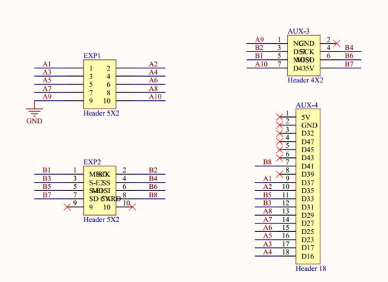
here's the minor changes i've made, i hope like hell that the LCD data lines are bit-banged...
so that's a few data lines and also 5V is now 3.3v.
let's have a look in Marlin... picking pins_RAMPS.h just... because. okaaay... line 250 onwards...
[github.com]
#if ENABLED(GRAPHICAL_LCD) that's an SPI-based screen, all good there.
NEWPANEL, PANEL_ONe... LCD_PINS_RS 40 or 16, ENABLE 17, -D7 23, 25, 27, 29 so matching with those A4 to A7 lines... now where the hell are these actually used...
errr.... worra?? ahh ok, ultralcd_impl_HD44780.h LiquidCrystal lcd(LCD_PINS_RS .... ) which is Read select, enable, D4, D5, D6, D7. okaay. and that's apparently a standard library file, LiquidCrystal.cpp.... let's track down a random implementation... 1.5.4 will do... arduino-1.5.4/libraries/LiquidCrystal/src/LiquidCrystal.cpp
aaand that's bit-banged. whew. makes extensive use of digitalWrite which is a single-bit function.
ok so it doesn't actually matter precisely what pins are put onto AUX-4. which is good... because i changed them

the only other thing to check is, is there at least one LCD that can be powered from 3.3v. HD44780 datasheet [www.sparkfun.com]
2.7 to 5.5v. excellent.
"wide range of power" 3.0 to 11v. excellent.
ok so that all looks good.
thanks for encouraging me to go over this, i honestly wouldn't have checked otherwise, just... hoped

|
Re: RAMPS 1.4.2 fork: RD3D v1.0 (6 steppers, 24v, Due) September 19, 2017 02:34PM |
Registered: 8 years ago Posts: 776 |
ok so some progress (next revision modifications), aside from anything i spotted an error in the PCB that's been sent off yesterday, Arduino 5V was still wired in, up in the top right corner on the 2x18 connector, and i didn't realise it was. so it was converted to... 3.3v. which means 3.3v is hard-wired to 5.0v. whoops. fortunately i can cut those tracks.
anyway, i realised that there's actually very little in the way of a GND plane for the critical power provision. as an extremely high-component-count 2-layer PCB, the GND plane is extremely fragmented. so - at the expense of messing with the look of the board, i turned the power connector round, turned the 11A+ fuse round, and increased the width of the GND copper leading from both terminals of the power connector.
then, by using a HUGE power plane from the fuse output on the TOP layer, and using small ones on BOTTOM surrounding the fuse output terminal and the MOSFET power terminal, and dumping a whole wodge of VIAs around each, i was able to get a massive wide lane of GND copper *in between* them, on the BOTTOM layer, which then goes all the way up the left side, joining with several VIAs to TOP along the way.
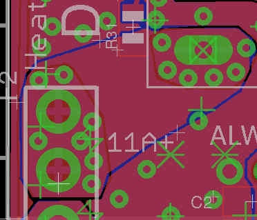
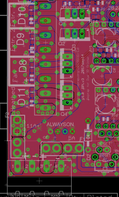
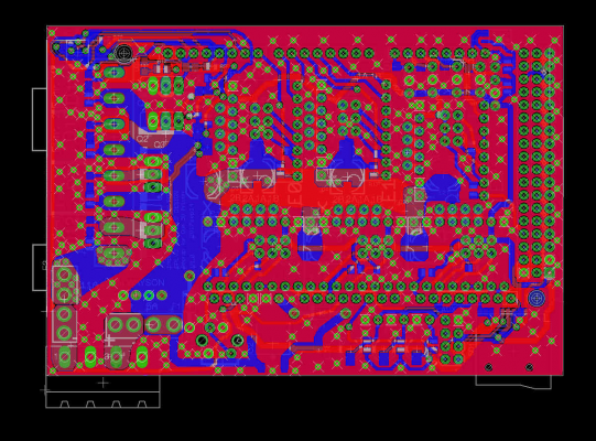
here's how the left-hand side looks: you can see that the main 5A (+12V instead of +12V2) track goes in a huge lane up the middle, then branches off left (to each MOSFET) and right to the steppers. however it's not that simple: GND has been VIA'd all the way as well (paying attention to bringing in branches from that *left* side as well as making use of the GND plane *underneath* that main +12V channel).
however it goes further than that: on the steppers i've made sure that there are at least two VIAs either side of any GND pin, and likewise with the VMOT (+12V) supply:
the polulu module pins are specified as a 3A rating in the BOM, but my primary concern is that just having a GND (or power) plane below and connecting each plane *only* via that pin would be problematic. by adding a couple of VIAs, at least power can be shared between the VIAs *and* the pin when transferring between TOP and BOTTOM layers.
basically what i seem to be working towards, here, is the possibility of using TMC2560 stepper driver modules (with a HELL of a lot of forced-air cooling) DRV8825 is supposed to be 2A (but has its own problems...)
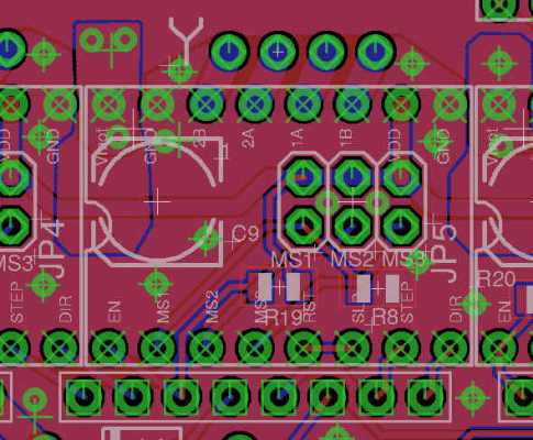
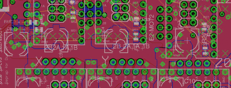
... and i'm not happy with how things are. what's happening is that there's so many tracks that they're criss-crossing and cutting off GND supply to the top 3 modules. it's so cramped that i can't make a proper assessment... so i'm going to turn E0, E1 and E2 round through 90 degrees. this will bring the VMOT supply pins all conveniently close together to a central "spine", but, crucially, leave enough room *for* that central spine: +12V on the BOTTOM layer and GND on TOP. the nice thing is, even the Capacitors are obliging as they can be turned through 180 to sit across the GND-VMOT planes. haven't done the routing but here it is:
so, the positions of the 3 lower modules are not changing: their GND and VMOT are in top *left*. the other 3 are rotating, and those have their GND and VMOT in the *bottom* left. getting the stepper connectors in is going to be very tight, but that's reasonably acceptable.
waa quite a lot of unexpected work!
anyway, i realised that there's actually very little in the way of a GND plane for the critical power provision. as an extremely high-component-count 2-layer PCB, the GND plane is extremely fragmented. so - at the expense of messing with the look of the board, i turned the power connector round, turned the 11A+ fuse round, and increased the width of the GND copper leading from both terminals of the power connector.
then, by using a HUGE power plane from the fuse output on the TOP layer, and using small ones on BOTTOM surrounding the fuse output terminal and the MOSFET power terminal, and dumping a whole wodge of VIAs around each, i was able to get a massive wide lane of GND copper *in between* them, on the BOTTOM layer, which then goes all the way up the left side, joining with several VIAs to TOP along the way.
here's how the left-hand side looks: you can see that the main 5A (+12V instead of +12V2) track goes in a huge lane up the middle, then branches off left (to each MOSFET) and right to the steppers. however it's not that simple: GND has been VIA'd all the way as well (paying attention to bringing in branches from that *left* side as well as making use of the GND plane *underneath* that main +12V channel).
however it goes further than that: on the steppers i've made sure that there are at least two VIAs either side of any GND pin, and likewise with the VMOT (+12V) supply:
the polulu module pins are specified as a 3A rating in the BOM, but my primary concern is that just having a GND (or power) plane below and connecting each plane *only* via that pin would be problematic. by adding a couple of VIAs, at least power can be shared between the VIAs *and* the pin when transferring between TOP and BOTTOM layers.
basically what i seem to be working towards, here, is the possibility of using TMC2560 stepper driver modules (with a HELL of a lot of forced-air cooling) DRV8825 is supposed to be 2A (but has its own problems...)
... and i'm not happy with how things are. what's happening is that there's so many tracks that they're criss-crossing and cutting off GND supply to the top 3 modules. it's so cramped that i can't make a proper assessment... so i'm going to turn E0, E1 and E2 round through 90 degrees. this will bring the VMOT supply pins all conveniently close together to a central "spine", but, crucially, leave enough room *for* that central spine: +12V on the BOTTOM layer and GND on TOP. the nice thing is, even the Capacitors are obliging as they can be turned through 180 to sit across the GND-VMOT planes. haven't done the routing but here it is:
so, the positions of the 3 lower modules are not changing: their GND and VMOT are in top *left*. the other 3 are rotating, and those have their GND and VMOT in the *bottom* left. getting the stepper connectors in is going to be very tight, but that's reasonably acceptable.
waa
 quite a lot of unexpected work!
|
Re: RAMPS 1.4.2 fork: RD3D v1.0 (6 steppers, 24v, Due) September 20, 2017 08:23AM |
Registered: 8 years ago Posts: 776 |
ow. i really must stop doing this kind of work overnight!
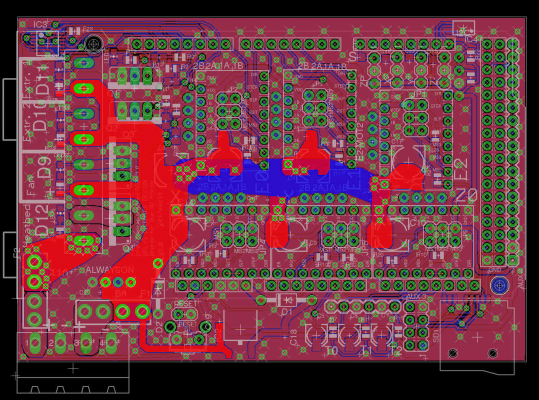
okaay so here's the reorganised steppers, the top 3 have been rotated through 90 degrees, and it actually makes for a far, far cleaner board layout. one of the reasons why the original board has reduced GND connectivity is because of the huge numbers of tracks criss-crossing the board: even with the rule of having top tracks go left-right and bottom tracks go up-down it results in high fragmentation on 2-layer boards.
by turning the top 3 steppers by 90 degrees the distance for the traces to travel from the arduino headers to each module is greatly reduced, they don't have to traverse a module to get there, and more than that a gap opens up between each stepper module.
so here's what the GND fill looks like. you can see it flows through the arduino pins and also the gaps between stepper header pins, but also (slightly unclear, apologies) the major clear areas where there's bit chunky wide bits are all connected to other big chunky wide bits. this allows me to get good GND connectivity to the critical areas such as the MOSFETs and the *two* GND pins on each stepper.
mainly, the previous layout with so little space between the stepper modules, in combination with so many tracks cutting up the space top-bottom, was preventing and prohibiting not just those GND stepper pins from having good connectivity but also making it *really* difficult to get a clear idea of what the heck is going on.
the power was a similar story. bottom left is +12V2 (which can now do 24v... should rename that..). tiat's quite straightforward as now the fuse is inline with the connector. +12V has that large channel going up the middle, brances off to the MOSFETs, but where previously there had to be TWO separate channels, one above the first set of module pins (because there was no space to get in between them), now the bottom left VMOT pin of each of the top steppers is... right there, easy to connect straight to that horizontal channel.
double-connection with a few VIAs to the copper pours underneath each 100uF capacitor and we're good. there's even room now to drop in some 0.1uF decoupling capacitors right next to each VMOT pin. i don't precisely know why this is done but it's something i've seen a lot of so am copying that.
anyway now that the board layout is a hell of a lot cleaner i actually have room, ironically, to put all six endstops back in, plus just enough room to put the remaining 11 or so pins i had to drop from the 2x18 arduino connector *back* onto an AUX header. yay! i think there's like... only 1 or 2 pins that aren't wired up, now.
|
Re: RAMPS 1.4.2 fork: RD3D v1.0 (6 steppers, 24v, Due) September 20, 2017 11:57AM |
Registered: 8 years ago Posts: 776 |
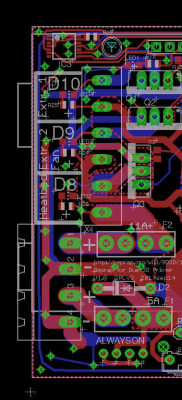
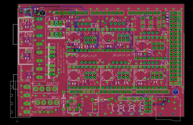
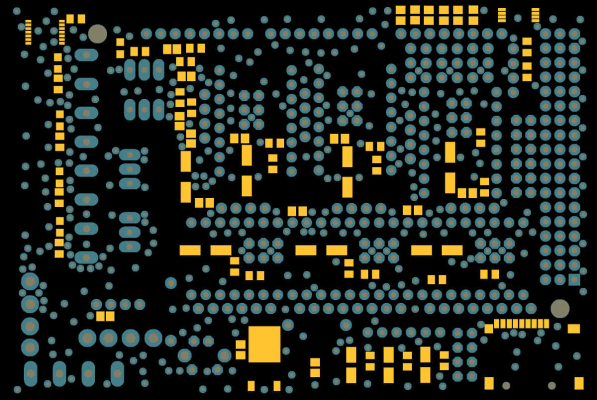
*splutter* oh my god, get a load of this! it's an overlay of the gerbers of the stencil, footprints and drill-holes.... and this is only a 4in x 2.7in PCB, there's hardly a space on it that isn't drilled to the eyeballs! where.. where's the space to put the tracks?? 

Sorry, only registered users may post in this forum.
