RAMPS 1.4.2 fork: RD3D v1.0 (6 steppers, 24v, Due)
Posted by lkcl
|
Re: RAMPS 1.4.2 fork: RD3D v1.0 (6 steppers, 24v, Due) October 24, 2017 03:08AM |
Registered: 8 years ago Posts: 776 |
Quote
Dust
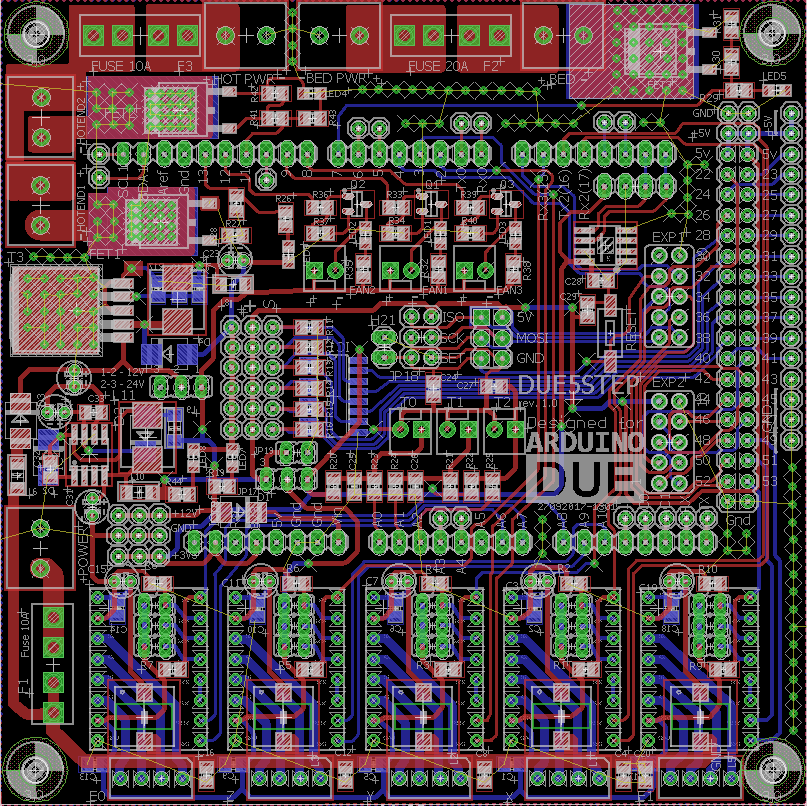
Some mounting holes might be nice.... cant see any
oh! on the A4982-DSB? yes sorry that's an out-of-date picture, already. funny. the z-height sensor, i figured it's so tiny that you just create a holder / clip around the 2x4 connector, instead.
it's not quite the same size as the TMC2660-DSB, that one's quite a bit bigger. the STM8S programming / UART interface is in the middle. despite it being a 2-layer board i've made it large enough to keep most of the BOTTOM layer entirely free as a GND plane (thx for that tip, dc42). there are a *few* breaks in it around the steppers, and quite a few in the middle around the STM8S, but i made sure (with one exception which i seem to have missed) that every single one of the traces on BOTTOM is completely surrounded by GND flood-fill.

|
Re: RAMPS 1.4.2 fork: RD3D v1.0 (6 steppers, 24v, Due) October 24, 2017 08:56AM |
Registered: 7 years ago Posts: 23 |
|
Re: RAMPS 1.4.2 fork: RD3D v1.0 (6 steppers, 24v, Due) October 24, 2017 09:26AM |
Registered: 8 years ago Posts: 776 |
Quote
xebbmw
@lkcl: why not use A5984 stepper driver for the dual stepper board? It can be configured up to 32 micro steps and it less noisier than A4982. In my opinion it is a better choice but depends on the actual cost for the chip (although at Digikey A5984 is less expensive than A4982).
... because i'm a fool that's rushed ahead with that particular board design without consulting anyone here, that's why
 always a mistake: i wanted to at least get something ready which wasn't as costly as the TMC2660 board, but couldn't bring myself to use the A4988.
looking at it now: it looks much better, doesn't it? up to 40V, adaptive fast decay algorithm or something giving reduced noise and less lost steps, and has 3 MS config pins like the A4988 instead of only 2 like the A4982. the only thing being, we're outta pins on the 20-pin TSSOP STM8S003F6P6.... might have to go to the shock-horror... $0.50 STM8S03K3T6C instead! wow that's double the cost maaan
a whole extra $0.25, i can hardly bear the suspense at the increased cost.i think then, that will be the next board (but not for a few weeks: i think 6 PCBs in under a month is quite enough for now!) also i will however have to check that the ICs are available in Huaqiang Rd, the listings on taobao are suspiciously uniform and sparse. the numbers (and the prices) for the A4988 are mad (huge numbers of sellers, ridiculously-low prices), whereas the A4982 is at least available (some vendors), but the A5984 has very few and they look the same. i'll have to ask a vendor if they can get hold of it.
|
Re: RAMPS 1.4.2 fork: RD3D v1.0 (6 steppers, 24v, Due) October 24, 2017 10:37PM |
Registered: 7 years ago Posts: 23 |
|
Re: RAMPS 1.4.2 fork: RD3D v1.0 (6 steppers, 24v, Due) October 25, 2017 03:19AM |
Registered: 8 years ago Posts: 776 |
Quote
xebbmw
Can you point me to an eagle library for A4982? In the allegro library i did not find one for tssop24 package...
for some strange reason i actually seem to have one, and i don't _actually_ know where it originated! you can of course use the eagle exp-lbrs ULP to grab it. i've done that for you, it turns out to be something called RepRapjr.lbr, i remember grabbing a copy of that from somewhere (google it). anyway - it's all here: [hands.com]
|
Re: RAMPS 1.4.2 fork: RD3D v1.0 (6 steppers, 24v, Due) October 25, 2017 09:29AM |
Registered: 7 years ago Posts: 23 |
Thanks, I just realized I am already using that library. I am designing a 5 steppers board using Polulu drivers for Arduino Due, but I did not checked before that library.
Some ideas that I use and you might include then in your RAMPS 1.4.2: I added to my board is a DC-DC switching converter for 5V (the purpose is to supply power to a graphic display). In the same time Polulu drivers can be driven by a power supply of 3.3 or 5V using a jumper. Also I have a DC-DC switching converter for 12V on the board so I could supply the board with 24V (for example for stepper motors). The fans are powered from 12V.
Some ideas that I use and you might include then in your RAMPS 1.4.2: I added to my board is a DC-DC switching converter for 5V (the purpose is to supply power to a graphic display). In the same time Polulu drivers can be driven by a power supply of 3.3 or 5V using a jumper. Also I have a DC-DC switching converter for 12V on the board so I could supply the board with 24V (for example for stepper motors). The fans are powered from 12V.
|
Re: RAMPS 1.4.2 fork: RD3D v1.0 (6 steppers, 24v, Due) October 25, 2017 10:46AM |
Registered: 8 years ago Posts: 776 |
Quote
xebbmw
Thanks, I just realized I am already using that library. I am designing a 5 steppers board using Polulu drivers for Arduino Due,
nice! have you published the schematics and pcb file so that i (and anyone else) can take a look?
Quote
but I did not checked before that library.
yeh i didn't know it was there, i encountered it by accident when i found the stepstick (A4988) eagle files.
Quote
Some ideas that I use and you might include then in your RAMPS 1.4.2:
RD3D not RAMPS 1.4.2
Quote
I added to my board is a DC-DC switching converter for 5V (the purpose is to supply power to a graphic display).
most of the LCD controllers i've seen - actually most arduino-style shields - use 3.3v ICs that are 5V tolerant.
Quote
In the same time Polulu drivers can be driven by a power supply of 3.3 or 5V using a jumper. Also I have a DC-DC switching converter for 12V on the board so I could supply the board with 24V (for example for stepper motors). The fans are powered from 12V.
ha, the amount of space available in the RD3D is... well... it's ridiculously tight. i actually can't fit any more components on the PCB! however for the next version i'm planning to drop 2 of the polulus possibly even 4 (so only having 4 or even just 2), and to replace them with the 14-pin dual-headers. that would free up some space (and some pins)
it would be great to see clearly the design you've come up with, if you can publish the eagle files i can take a look, you wouldn't need to explain it in words (which are often hard to get right and take a lot of time)
|
Re: RAMPS 1.4.2 fork: RD3D v1.0 (6 steppers, 24v, Due) October 25, 2017 05:19PM |
Registered: 7 years ago Posts: 23 |
Sorry, my mistake hereQuote
lkcl
RD3D not RAMPS 1.4.2
I agree with you here, but my understanding is that a graphic controller would absorb a lot of current comparing with how much the Arduino Due might deliverQuote
lkcl
Most of the LCD controllers i've seen - actually most arduino-style shields - use 3.3v ICs that are 5V tolerant.
My design is based on DUE3DOM board from here. As I said is not finished yet. I have included 5 steppers, one heat bed output, two hot end outputs and three fans. My printer is a delta kossel that is driven by a RAMPS with ATMEGA2550. I have one spare board Arduino DUE that I want to use it with the new shield.Quote
lkcl
it would be great to see clearly the design you've come up with, if you can publish the eagle files i can take a look, you wouldn't need to explain it in words (which are often hard to get right and take a lot of time)
Edited 1 time(s). Last edit at 10/25/2017 08:17PM by xebbmw.
|
Re: RAMPS 1.4.2 fork: RD3D v1.0 (6 steppers, 24v, Due) October 26, 2017 02:30AM |
Registered: 8 years ago Posts: 776 |
Quote
xebbmw
Sorry, my mistake hereQuote
lkcl
RD3D not RAMPS 1.4.2
I agree with you here, but my understanding is that a graphic controller would absorb a lot of current comparing with how much the Arduino Due might deliverQuote
lkcl
Most of the LCD controllers i've seen - actually most arduino-style shields - use 3.3v ICs that are 5V tolerant.
look carefully at the schematic of RD3D. which - hint hint - has been available throughout the ENTIRE DEVELOPMENT PROCESS OF THE BOARD. (not "i'm gonna publish it when it's finished". people have been able to help me spot mistakes as a result).
there are very specific reasons why the power has been routed the way that it has been routed. i will document this later today in the wiki page so that you can understand it.
if you use on-board regulators that could provide different voltages from the Arduino/Due on-board regulators (which they WILL do, due to variations in current usage) you also have to use level-shifters on ALL GPIO. if at any time the voltage inputted into a GPIO pin of a Due EXCEEDS the Due's 3.3v regulated voltage, you end up forcing power into the Due via a GPIO pin that cannot cope. you end up actually POWERING the ATSAM3X via that GPIO pin, and that will damage it.
this is why you have VREF and AREF on the Arduino and the Due. i'll document it fully later.
Quote
My design is based on DUE3DOM board from here. As I said is not finished yet.Quote
lkcl
it would be great to see clearly the design you've come up with, if you can publish the eagle files i can take a look, you wouldn't need to explain it in words (which are often hard to get right and take a lot of time)
did you see me saying that, throughout the development process of RD3D? did i say, "i'm sorry, i'm not going to publish this work because it's quotes not finished quotes?"
now nobody can understand fully what you are saying, they can't help you if it's not easy to follow what you're doing. they can't see it, they can't contribute. you are the sole exclusive person who can work on it.
not publishing what you're doing also makes your life incredibly difficult. you have to explain - fully - in words - exactly what you're doing.
|
Re: RAMPS 1.4.2 fork: RD3D v1.0 (6 steppers, 24v, Due) October 26, 2017 05:26AM |
Registered: 13 years ago Posts: 7,616 |
Quote
lkcl
not publishing what you're doing also makes your life incredibly difficult.
Yes and No. With Gen7 I initially published work in progress, too. The result was, people etched and soldered PCBs from this half-finished work and found it not working (as expected). Asking to read instructions is asking too much from average users :-)
| Generation 7 Electronics | Teacup Firmware | RepRap DIY |
|
Re: RAMPS 1.4.2 fork: RD3D v1.0 (6 steppers, 24v, Due) October 26, 2017 05:59AM |
Registered: 8 years ago Posts: 776 |
Quote
Traumflug
Quote
lkcl
not publishing what you're doing also makes your life incredibly difficult.
Yes and No. With Gen7 I initially published work in progress, too. The result was, people etched and soldered PCBs from this half-finished work and found it not working (as expected). Asking to read instructions is asking too much from average users :-)
how exactly did you publish them? did you push a tarball or zip file out at people, or a package containing gerber files? that's usually taken as a sign of a "Release", and you would be expected to put some indication of the status of the files *in the archive's file name*.
what i tend to do is publish *only* the git repository (deliberately not using the proprietary SaaSS github) so that *intelligent* users can, obviously, grab it from the repository. not even publishing the location of the gerber files, because, like you said, the average user will not understand that they're not ready.
with only a git repository, particularly one that is *not* on github, average users will start to ask "uhhhhnn... where are the geerbeeeers?? i carntt find deeemm" and that's the point at which you can tell them "the board's in development".
if someone goes to the trouble of generating the gerbers themselves, doesn't follow the forum, doesn't read the wiki page, doesn't see that the wiki page says EXPERIMENTAL at the top, doesn't see that the archive is named "experimental", doesn't read the README and so on... then... well... with that many safety-checks and status check, all of which they completely ignored, they get exactly what they asked for. i don't see that as being a problem, but an important lesson for them
Edited 1 time(s). Last edit at 10/26/2017 06:00AM by lkcl.
|
Re: RAMPS 1.4.2 fork: RD3D v1.0 (6 steppers, 24v, Due) October 26, 2017 06:43AM |
Registered: 13 years ago Posts: 7,616 |
Quote
lkcl
how exactly did you publish them?
'git push' of the design files, no Gerbers.
| Generation 7 Electronics | Teacup Firmware | RepRap DIY |
|
Re: RAMPS 1.4.2 fork: RD3D v1.0 (6 steppers, 24v, Due) October 26, 2017 07:22AM |
Registered: 8 years ago Posts: 776 |
Quote
Traumflug
Quote
lkcl
how exactly did you publish them?
'git push' of the design files, no Gerbers.
... and people still went ahead with sending them to factories, without any kind of announcement or communication along the lines of "i'm going to send these to a factory, is that a good idea yes or no?"? yeehhh they get what they deserve: not your problem if people don't communicate. the trade-off is: "terminate all communication and publication so that idiots who can't or won't read or communicate don't waste their money" or "communicate and collaborate so that mistakes are not made and the people who *do* wish to communicate, collaborate and make sure that the design is good, and enjoy the process of working with other people" i know exactly what choice i would make, every time, and sleep well at night having made it.
|
Re: RAMPS 1.4.2 fork: RD3D v1.0 (6 steppers, 24v, Due) October 26, 2017 08:21AM |
Registered: 13 years ago Posts: 7,616 |
Quote
lkcl
... and people still went ahead with sending them to factories, without any kind of announcement or communication along the lines of "i'm going to send these to a factory, is that a good idea yes or no?"?
First of all, the point of a Gen7 is that one needs no factory. Interested people can download the design and make PCB and controller on their kitchen table.
Regarding communications: all you'll see is a "This design doesn't work!" in the forum. After the fact, of course. And then everybody knows: "Stay away, this design doesn't work!". People will find this by googling and find it after a working release was published, too, of course. One negative comment outweights 5 or 10 positive comments, so your design is down the toilet before its first release already.
The only way to deal with this is to publish finished work, only. Works.
If you want to discuss aspects, publish informative, but unusable sections, only. Like partial schematics as PNGs. And also only inside discussions, so people immediately see what's going on.
| Generation 7 Electronics | Teacup Firmware | RepRap DIY |
|
Re: RAMPS 1.4.2 fork: RD3D v1.0 (6 steppers, 24v, Due) October 26, 2017 08:37AM |
Registered: 8 years ago Posts: 776 |
great!Quote
Traumflug
Quote
lkcl
... and people still went ahead with sending them to factories, without any kind of announcement or communication along the lines of "i'm going to send these to a factory, is that a good idea yes or no?"?
First of all, the point of a Gen7 is that one needs no factory. Interested people can download the design and make PCB and controller on their kitchen table.
Quote
Regarding communications: all you'll see is a "This design doesn't work!" in the forum.
so, that would be followed up with a link to the FAQ answer, "it's not ready, you should have communicated and aske about it first". i don't see the problem.
Quote
After the fact, of course. And then everybody knows: "Stay away, this design doesn't work!".
all the people who *don't read* will make their own (broken) conclusions confirming their own bias, regardless of what you do or say. there's not a lot that can be done about that.
Quote
People will find this by googling and find it after a working release was published, too, of course. One negative comment outweights 5 or 10 positive comments, so your design is down the toilet before its first release already.
a negative comment only outweighs a positive comment if it's left to fester.... and that only happens if you don't respond correctly (or at all). if they start getting completely out of hand - totally irate - then that's what moderation (and banning people) is for.
i've had to do that on lists that i manage. not fun, but there's a series of advisory guidelines to escalate up the chain. if people _really_ don't listen, you simply have to take the unfortunate but necessary action to ban them and remove their comments from the forum.
so again, i don't perceive the quotes negative comments quotes to be a problem. they're only a "problem" if you don't deal with them.
Quote
The only way to deal with this is to publish finished work, only. Works.
... with the side-effect of terminating the possibility for people to collaborate fully with you, as they wish to, on their terms (not yours)
Quote
If you want to discuss aspects, publish informative, but unusable sections, only. Like partial schematics as PNGs. And also only inside discussions, so people immediately see what's going on.
... which is a lot of work (i've done "publishing of sections by taking screenshots" and it's hard work). it also sets you up as the de-facto and sole exclusive "gateway" developer / controller of the project.
people don't *want* to collaborate on something that is exclusively controlled. take the stl47o board i published on arduino.cc during its development (the users there are intelligent enough to realise that it *is* in development). one person - westfw - was actually doing git pull requests and said, "hmm it would be good if i could help out" so i said "sure!". he made some really useful cleanup changes... i incorporated them and carried on. saved me a huge amount of time! particularly as i have (had) 5 other PCBs to develop around the same time.
... with the "i'll publish it when it's finished" approach, that possibility goes completely out the window. i don't WANT to be the sole exclusive developer. after 20 years of developing in public i know that i can't stand the feeling of setting myself up as "God Of The Project". yes i've had it happen, people practically worshipping me rather than thinking for themselves. i had to be very very diplomatic with them, and very careful.
i also *want* to help other people with their projects. the approach of "i'll publish it when it's finished" terminates any such possibility absolutely stone-dead.
Edited 1 time(s). Last edit at 10/26/2017 08:39AM by lkcl.
|
Re: RAMPS 1.4.2 fork: RD3D v1.0 (6 steppers, 24v, Due) October 26, 2017 01:01PM |
Registered: 8 years ago Posts: 776 |
Quote
xebbmw
I agree with you here, but my understanding is that a graphic controller would absorb a lot of current comparing with how much the Arduino Due might deliverQuote
lkcl
Most of the LCD controllers i've seen - actually most arduino-style shields - use 3.3v ICs that are 5V tolerant.
ok so as promised i wrote up the design considerations for power provision:
[reprap.org]
in short, the due provides sufficient 3.3v current, the arduino provides sufficient 5.0v current, so you don't need a regulator, you just select whichever's needed (that's if you want a dual arduino/due-capable board).
if you want a due-only board you can just route 3.3v through to expansion headers, as there's more than enough current and most "shields" - i prefer the word peripherals - are 3.3v ICs that are 5v tolerant. there's a few exceptions but i've not yet encountered any peripherals that were actually needed for the (specialist) use of a 3D printer / CNC controller board.
|
Re: RAMPS 1.4.2 fork: RD3D v1.0 (6 steppers, 24v, Due) October 26, 2017 05:07PM |
Registered: 10 years ago Posts: 14,672 |
Does the Arduino Due provide sufficient 5V current without overheating the voltage regulator if you feed 24V to the power input pin (if it can accept 24V) and you are powering a 12864 LCD from +5V? I very much doubt it. One of the well-known flaws of Arduino/RAMPS is that if you use a 12864 LCD, the voltage regulator on the Arduino mega is likely to overheat even at 12V input.
Large delta printer [miscsolutions.wordpress.com], E3D tool changer, Robotdigg SCARA printer, Crane Quad and Ormerod
Disclosure: I design Duet electronics and work on RepRapFirmware, [duet3d.com].
Large delta printer [miscsolutions.wordpress.com], E3D tool changer, Robotdigg SCARA printer, Crane Quad and Ormerod
Disclosure: I design Duet electronics and work on RepRapFirmware, [duet3d.com].
|
Re: RAMPS 1.4.2 fork: RD3D v1.0 (6 steppers, 24v, Due) October 26, 2017 05:47PM |
Registered: 8 years ago Posts: 776 |
Quote
dc42
Does the Arduino Due provide sufficient 5V current without overheating the voltage regulator if you feed 24V to the power input pin (if it can accept 24V) and you are powering a 12864 LCD from +5V? I very much doubt it. One of the well-known flaws of Arduino/RAMPS is that if you use a 12864 LCD, the voltage regulator on the Arduino mega is likely to overheat even at 12V input.
when talking to people on arduino.cc (particularly westfw) during the development of the STL47o (a due clone that uses the low-cost STM32L471.. or it would if it was actually possible to get in Shenzhen, i'll use the GD32450 and/or the STM32F427 instead...) i learned about power dissipation on the voltage regulators.
what you're referring to, dc42, as i understand it, is that some of these LDO regulators work like a car brake, in effect diverting the extra voltage directly into heat. so if you supply them with 8V and demand 1A current it's fine... but if you put in 12v and demand 1A current, the LDO regulator throws off all of that extra power (12-5 volts times 1A = 7 watts!!) as heat. this is what the "thermal dissipation" figure is about in the datasheet.
having learned about this i chose to use the beefier (TO-252) of the two options shown in the Arduino Mega 2560 Reference Design for the STL47o.
but, also, for RD3D, i deliberately chose to put in an MC7808, which handles the conversion from anywhere up to 35 volts down to 8 volts on the RD3D board, not the Arduino / Due. now that you mention it, and now that i know a bit more about power regulator thermal dissipation i should do a proper review of the MC7808. if i am honest i picked it near-arbitrarily, based on cost (low) and package size (large). reviewing it now:
[www.onsemi.com]
i believe i was.. hopelessly wrong about the selection of this regulator
i don't know why i selected it, i thought a single regulator IC would be simpler, instead of using a buck converter, which now that i know what i do about thermal dissipation i can appreciate now why they're used to convert higher voltages down to much lower (stable) ones, they do it through PWM, an inductor to stabilise that, and continuous feedback/monitoring, very smart.
so ho hum there will be a 3rd revision of RD3D, but i will at least have something that works to take to SZMF.
|
Re: RAMPS 1.4.2 fork: RD3D v1.0 (6 steppers, 24v, Due) October 26, 2017 06:06PM |
Registered: 9 years ago Posts: 978 |
Quote
lkcl
what you're referring to, dc42, as i understand it, is that some of these LDO regulators work like a car brake, in effect diverting the extra voltage directly into heat. so if you supply them with 8V and demand 1A current it's fine... but if you put in 12v and demand 1A current, the LDO regulator throws off all of that extra power (12-5 volts times 1A = 7 watts!!) as heat. this is what the "thermal dissipation" figure is about in the datasheet.
This kind of voltage regulation sounds appalling to me. For 65c you can buy a DC-DC buck converter that is claimed to be 97% efficient. Worst case, you could have a couple of pins on your board to accept 5V, perhaps placed the right distance apart for the buck converter to be soldered directly to them. Best case, build the buck converter circuit into the board itself.
Or am I missing something?
|
Re: RAMPS 1.4.2 fork: RD3D v1.0 (6 steppers, 24v, Due) October 26, 2017 07:22PM |
Registered: 10 years ago Posts: 14,672 |
What you are missing is that many of the cheap buck converters produce tons of EMI. This is not usually a problem for the hobbyist making something for his own use, but is an issue for anyone making equipment for sale.
Large delta printer [miscsolutions.wordpress.com], E3D tool changer, Robotdigg SCARA printer, Crane Quad and Ormerod
Disclosure: I design Duet electronics and work on RepRapFirmware, [duet3d.com].
Large delta printer [miscsolutions.wordpress.com], E3D tool changer, Robotdigg SCARA printer, Crane Quad and Ormerod
Disclosure: I design Duet electronics and work on RepRapFirmware, [duet3d.com].
|
Re: RAMPS 1.4.2 fork: RD3D v1.0 (6 steppers, 24v, Due) October 26, 2017 10:02PM |
Registered: 7 years ago Posts: 23 |
for me electronics and 3d printers is just a hobby. this is my first experience with such a complex board. see my board in the attachment:Quote
lkcl
did you see me saying that, throughout the development process of RD3D? did i say, "i'm sorry, i'm not going to publish this work because it's quotes not finished quotes?"
now nobody can understand fully what you are saying, they can't help you if it's not easy to follow what you're doing. they can't see it, they can't contribute. you are the sole exclusive person who can work on it.
not publishing what you're doing also makes your life incredibly difficult. you have to explain - fully - in words - exactly what you're doing.
Quote
lkcl
Quote
xebbmw
I agree with you here, but my understanding is that a graphic controller would absorb a lot of current comparing with how much the Arduino Due might deliver
in short, the due provides sufficient 3.3v current, the arduino provides sufficient 5.0v current, so you don't need a regulator, you just select whichever's needed (that's if you want a dual arduino/due-capable board).
if you want a due-only board you can just route 3.3v through to expansion headers, as there's more than enough current and most "shields" - i prefer the word peripherals - are 3.3v ICs that are 5v tolerant. there's a few exceptions but i've not yet encountered any peripherals that were actually needed for the (specialist) use of a 3D printer / CNC controller board.
i will read your comments from wiki, thanks for providing those.
my board that i design is intended only for arduino due.
as dc42 mentioned
Quote
dc42
Does the Arduino Due provide sufficient 5V current without overheating the voltage regulator if you feed 24V to the power input pin (if it can accept 24V) and you are powering a 12864 LCD from +5V? I very much doubt it. One of the well-known flaws of Arduino/RAMPS is that if you use a 12864 LCD, the voltage regulator on the Arduino mega is likely to overheat even at 12V input.
the 5v regulator is needed to power a ReprapDiscount Full Graphic LCD. see other comments that i found about the issue here
as 5V DC-DC regulator i am looking to use RT7247B from Richtek. or should i use MP1484 (this is very cheap from Aliexpress). @dc42: any comments on these parts?
Edited 2 time(s). Last edit at 10/28/2017 07:44AM by xebbmw.
|
Re: RAMPS 1.4.2 fork: RD3D v1.0 (6 steppers, 24v, Due) October 27, 2017 02:43AM |
Registered: 8 years ago Posts: 776 |
Quote
frankvdh
This kind of voltage regulation sounds appalling to me. For 65c you can buy a DC-DC buck converter that is claimed to be 97% efficient. Worst case, you could have a couple of pins on your board to accept 5V, perhaps placed the right distance apart for the buck converter to be soldered directly to them. Best case, build the buck converter circuit into the board itself.
Or am I missing something?
you didn't miss anything: it's as truly dreadful as it sounds, from naive complete lack of experience on my part on using LDOs with such large voltages. yay! ridiculously, i'm actually using a Richtek part (the RT8288A) for several other projects. but, honestly, it was a cut/paste copy job where i wasn't actually fully understanding why it was being used. now i know.. ho hum...
if i had used the TO220A (through-hole) part there might have been a chance to put a heatsink on and get away with it, but nooo i wanted to save having 3 more drill-holes in a 4x3.25in PCB with nearly 1,000. whyyy...
|
Re: RAMPS 1.4.2 fork: RD3D v1.0 (6 steppers, 24v, Due) October 27, 2017 05:30AM |
Registered: 8 years ago Posts: 776 |
Quote
xebbmw
as dc42 mentioned
Quote
dc42
Does the Arduino Due provide sufficient 5V current without overheating the voltage regulator if you feed 24V to the power input pin (if it can accept 24V) and you are powering a 12864 LCD from +5V? I very much doubt it. One of the well-known flaws of Arduino/RAMPS is that if you use a 12864 LCD, the voltage regulator on the Arduino mega is likely to overheat even at 12V input.
the 5v regulator is needed to power a ReprapDiscount Full Graphic LCD. see other comments that i found about the issue here
their comments are not relevant as they supply only 5V and supply 5V directly to an on-board ATSAM3 *not* repeat *NOT* to a 7-12V to 5V regulator.
if you try to power the Due from that 5V regulator it will FAIL.
read the comments i wrote about level-shifting: if you try to power the 12864 LCD from 5V (whilst using the Due which does only 3.3v signalling i.e. outputs only 3.1 or 2.9v as HIGH depending on which pins you use) you will have to perform level-shifting on absolutely every single one of the LCD's pins. or, at least, analyse it very very carefully to make damn sure it's going to work.
Quote
as 5V DC-DC regulator i am looking to use RT7247B from Richtek. or should i use MP1484 (this is very cheap from Aliexpress). @dc42: any comments on these parts?
the MP1484 looks ok, follow dc42's advice though about selectng an extremely EMI-noisy buck converter. voltage limit on the MP1484 is 27v input. the RT7247B looks too low a max input voltage.
|
Re: RAMPS 1.4.2 fork: RD3D v1.0 (6 steppers, 24v, Due) October 27, 2017 06:56AM |
Registered: 8 years ago Posts: 776 |
[www.digikey.co.uk]
wanted to select the higher-frequency duck (quack) converters. top of that list is the AOZ1283 and AOZ1284. datasheet however is a leeetle obscure. taobao pricing on AOZ1284PI: around the USD $0.30 mark. recommended inductor: 22uH, peak efficiency 95%, VIN up to 36v which matches with the various MOSFETs and also being able to run A4988 (etc) steppers @ up to 365 as well.
i saw you use the A4403, dc42, which is a great IC, only thing it's a QFN.
i'm going to have to do a complete redesign here: there's not enough space for the buck converter. already sort-of planning that. i was thinking of splitting out the MOSFETs into a separate board as well, using a de-facto standard size and right-angle connector position, so as to be able to spear all the upright boards together with 3mm bolts.
the question would be then, where to put the buck converter. hmm... maybe even make that optional as well, as arduino / due boards can actually be supplied from a 7-12v DC power supply. hmm have to think about this.
|
Re: RAMPS 1.4.2 fork: RD3D v1.0 (6 steppers, 24v, Due) October 27, 2017 08:04AM |
Registered: 10 years ago Posts: 14,672 |
Buck converters are tricky things to get right, so unless you have the right experience, I advise against designing on one-board. I suggest you use a 7805 instead, which a user can add a heatsink to if necessary, or replace by one of the 7805-sized buck converters you can buy on eBay. This wouldn't be a good solution for a board to go in a manufactured 3D printer, but for a board aimed at hobbyists it's entirely adequate IMO.
Loads on the 3.3V rail are normally light, so the 3.3V regulator on the Arduino Due should be adequate.
Edited 2 time(s). Last edit at 10/27/2017 01:52PM by dc42.
Large delta printer [miscsolutions.wordpress.com], E3D tool changer, Robotdigg SCARA printer, Crane Quad and Ormerod
Disclosure: I design Duet electronics and work on RepRapFirmware, [duet3d.com].
|
Re: RAMPS 1.4.2 fork: RD3D v1.0 (6 steppers, 24v, Due) October 27, 2017 09:44AM |
Registered: 8 years ago Posts: 776 |
Quote
dc42
Busk converters are tricky things to get right, so unless you have the right experience, I advise against designing on one-board.
yehh i've done them before: i just wasn't expecting to use one here. as it's something that can be optional (7-12VC In to the Arduino) i'm considering also making it optional. that has the advantage of using something off-the-shelf or doing several iterations if needed.
Quote
I suggest you use a 7805 instead, which a user can add a heatsink to if necessary, or replace by one of the 7805-sized buck converters you can buy on eBay.
(or in the case of RD3D, the 7808). one with the TO-220 package only, yes. however... looking at the datasheet, if i'm interpreting it correctly, if the load increases to 1A and it's being supplied from 35V that's a whopping 27 WATTS to be shed off as heat, and i don't think even the TO-220 package with the largest possible heatsink could cope with that.
Quote
This wouldn't be a good solution for a board to go in a manufactured 3D printer, but for a board aimed at hobbyists it's entirely adequate IMO.
yeh RD3D is planned to go to production.
Quote
Loads on the 3.3V rail are normally light, so the 3.3V regulator on the Arduino Due should be adequate.
am counting on that in RD3D.
Edited 1 time(s). Last edit at 10/27/2017 09:45AM by lkcl.
|
Re: RAMPS 1.4.2 fork: RD3D v1.0 (6 steppers, 24v, Due) October 27, 2017 01:53PM |
Registered: 10 years ago Posts: 14,672 |
The load won't get anything like 1A in normal use. More like 200mA or possibly 250mA.
Large delta printer [miscsolutions.wordpress.com], E3D tool changer, Robotdigg SCARA printer, Crane Quad and Ormerod
Disclosure: I design Duet electronics and work on RepRapFirmware, [duet3d.com].
Large delta printer [miscsolutions.wordpress.com], E3D tool changer, Robotdigg SCARA printer, Crane Quad and Ormerod
Disclosure: I design Duet electronics and work on RepRapFirmware, [duet3d.com].
|
Re: RAMPS 1.4.2 fork: RD3D v1.0 (6 steppers, 24v, Due) October 27, 2017 04:19PM |
Registered: 8 years ago Posts: 776 |
Quote
dc42
The load won't get anything like 1A in normal use. More like 200mA or possibly 250mA.
it's for the peripherals as well, so it's including powering an LCD, the MicroSD card, W5500 SPI Ethernet, steppers and so on. on the RD3D, power is routed as follows:
* 12-35v DCIN ->
* 8v MC7808 ->
* Arduino 5V/3.3v ->
* 5V/3.3v back up to RD3D ->
path 1:
* RD3D power-jumper selector ->
* VCC ->
* AUX ports, steppers, one 74LVC125 buffer IC
path 2:
* 5V to MOSFET's 74LVC125
* 5V to MicroSD's 3.3v regulator
from what i remember, the W5500 takes 150mA peak, a MicroSD card somewhere around the same, LCD backlight would be... 250mA? it's why i picked the MC7808 in the first place, 1A load, thought it would be safe... didn't look at the thermal dissipation figure carefully... wark-wark
|
Re: RAMPS 1.4.2 fork: RD3D v1.0 (6 steppers, 24v, Due) October 30, 2017 03:59AM |
Registered: 8 years ago Posts: 776 |
new revision board arrived, this one with a THOUSAND drill-holes in it. more hole than board. makes swiss cheese look tame by comparison.

|
Re: RAMPS 1.4.2 fork: RD3D v1.0 (6 steppers, 24v, Due) October 30, 2017 06:46AM |
Registered: 7 years ago Posts: 363 |


Sorry, only registered users may post in this forum.