New RAMPS design
Posted by MrAlvin
|
Re: New RAMPS design July 03, 2018 12:00PM |
Registered: 14 years ago Posts: 140 |
|
Re: New RAMPS design July 03, 2018 12:10PM |
Registered: 9 years ago Posts: 93 |
|
Re: New RAMPS design July 03, 2018 03:43PM |
Registered: 10 years ago Posts: 14,672 |
You can use a portion of the flash memory in the Due as a substitute for EEPROM. It has lower write endurance than true EEPROM, but this is unlikely to be a problem. If necessary you can use wear levelling to mitigate it. Alternatively, use a file on the SD card to save the parameters, as the leading 32-bit firmwares do.
Edited 2 time(s). Last edit at 07/03/2018 03:44PM by dc42.
Large delta printer [miscsolutions.wordpress.com], E3D tool changer, Robotdigg SCARA printer, Crane Quad and Ormerod
Disclosure: I design Duet electronics and work on RepRapFirmware, [duet3d.com].
Edited 2 time(s). Last edit at 07/03/2018 03:44PM by dc42.
Large delta printer [miscsolutions.wordpress.com], E3D tool changer, Robotdigg SCARA printer, Crane Quad and Ormerod
Disclosure: I design Duet electronics and work on RepRapFirmware, [duet3d.com].
|
Re: New RAMPS design July 03, 2018 04:19PM |
Registered: 9 years ago Posts: 93 |
|
Re: New RAMPS design July 04, 2018 02:35AM |
Registered: 8 years ago Posts: 5,232 |
Quote
dc42
You can use a portion of the flash memory in the Due as a substitute for EEPROM. It has lower write endurance than true EEPROM, but this is unlikely to be a problem. If necessary you can use wear levelling to mitigate it. Alternatively, use a file on the SD card to save the parameters, as the leading 32-bit firmwares do.
Just out off curiosity: are you referring to SPIFFS from pellepl? I pulled my last hair out getting this to work on ESP8266. It seems it only reads char variables where unsigned char is the way to go.
Sorry for [OT]
|
Re: New RAMPS design July 04, 2018 02:47AM |
Registered: 10 years ago Posts: 14,672 |
No, I'm not referring to SPIFFS (although we used to use SPIFFS on the ESP8266 on the Duet WiFi and it worked OK for us). I am referring to a library which I think is called DueFlashStorage. We use an adapted version of it in the RepRapFirmware builds for Due/RADDS and the older Duets.
Large delta printer [miscsolutions.wordpress.com], E3D tool changer, Robotdigg SCARA printer, Crane Quad and Ormerod
Disclosure: I design Duet electronics and work on RepRapFirmware, [duet3d.com].
Large delta printer [miscsolutions.wordpress.com], E3D tool changer, Robotdigg SCARA printer, Crane Quad and Ormerod
Disclosure: I design Duet electronics and work on RepRapFirmware, [duet3d.com].
|
Re: New RAMPS design July 06, 2018 05:23PM |
Registered: 5 years ago Posts: 5 |
Reading the last page got my hopes up, the nucleo 144 would be a nice one to do as I too have a few around. Honestly it has way more pins and functions than we currently use. But it might kick the nucleo into the mainstream. Stm32 is pretty strong in other markets and an open source nucleo daughter card might help push a 32bit revolution.
|
Re: New RAMPS design July 07, 2018 09:57AM |
Registered: 14 years ago Posts: 140 |
Quote
dc42
You can use a portion of the flash memory in the Due as a substitute for EEPROM. It has lower write endurance than true EEPROM, but this is unlikely to be a problem. If necessary you can use wear levelling to mitigate it. Alternatively, use a file on the SD card to save the parameters, as the leading 32-bit firmwares do.
Thank you. Good to know.
As I am not much of a software-guy, I think I will, for now at least, just leave the space available for the EEPROM, and hope that either (or several) of the different solutions have already been implement in the different firmwares.
|
Re: New RAMPS design July 07, 2018 02:50PM |
Registered: 14 years ago Posts: 140 |
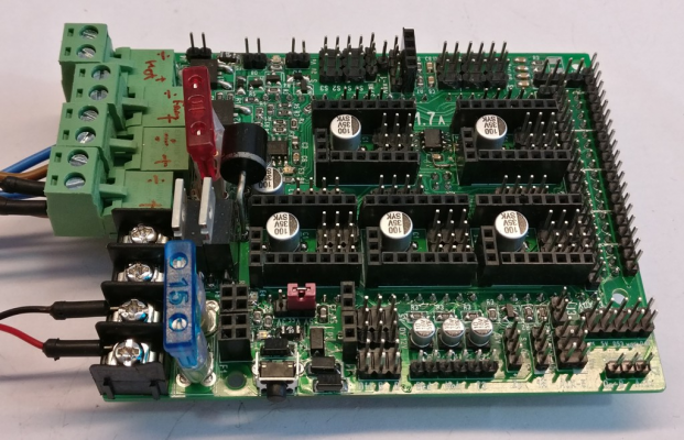
As the fuse testing in on a pause, while I await further fuse types to arrive, I decided to start testing the other elements on the board.
Before I started testing the fuses, I had already populated a board. Just to see if the intended components would fit.
To limit possibilities of errors in software configurations settings, I then proceed to make some small test skecthes, that would be targeted to each section of the board, like; eeprom, mosfets, temperature, end-stops, z-probe. These test sketches are included in the attached file: RAMPS17-Basics.zip
Here are two boards populated with the bare minimum (= all chip components), so I could see if both the board design and the test sketches would work.
Everything on the minimum-boards worked, on both an Arduino Mega 1280 and a Due.
But the eeprom did not respond on the fully populated board. Bummer! But fortunately a re-heating and re-soldering of the pins on the eeprom solved that problem.
I have successfully soldered in many, many smd chips on different boards, before this eeprom, but I suppose I was too eager to see if everything would fit, to pay propper attention to the visual double check of the solder connections of this eeprom chip. Fortunately a "quality-of-work test" revealed my mistake, before it caused too much trouble and head scratching.
I also discovered a missing pcb path for connecting a pull-down resistor to pin D10. This also has been fixed now.
Next will be testing of the stepper drivers.
Edited 1 time(s). Last edit at 07/07/2018 03:15PM by MrAlvin.
|
Re: New RAMPS design July 07, 2018 03:00PM |
Registered: 9 years ago Posts: 93 |
|
Re: New RAMPS design July 07, 2018 03:31PM |
Registered: 14 years ago Posts: 140 |
Quote
boelle
I like the screw terminals near the blue fuse
any chance the remaining 8 can be same type?
hmmm... unfortunately the pin spacing for the green connectors are 5.08mm and the black style screw terminals have a pin spacing of 7.62mm, so they are not easily interchangeable.
It is however possible to use other 5.08mm screw terminals, that are not like these green plug-in style.
See for instance this search on ebay Unfortunately I do not see any options for the same style as the black screw terminals on the 1.7 board.
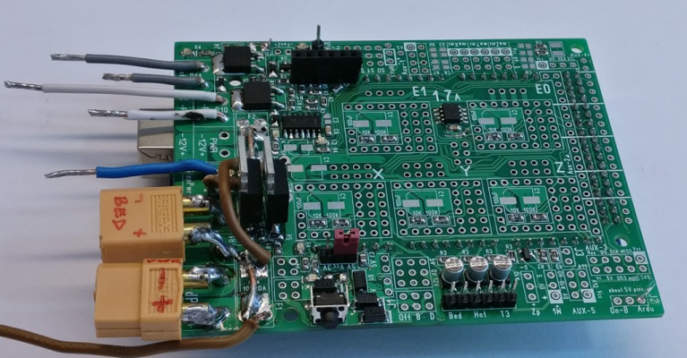
Personally, I like the advantage of being able to simply plug things in, so for the board I use to do the fuse testing, I have even replaced the black screw terminals with XT60 connectors.
Here is a picture of the current version of the board
|
Re: New RAMPS design July 07, 2018 03:36PM |
Registered: 9 years ago Posts: 93 |
|
Re: New RAMPS design July 08, 2018 02:40AM |
Registered: 8 years ago Posts: 5,232 |
I see a potential problem there:
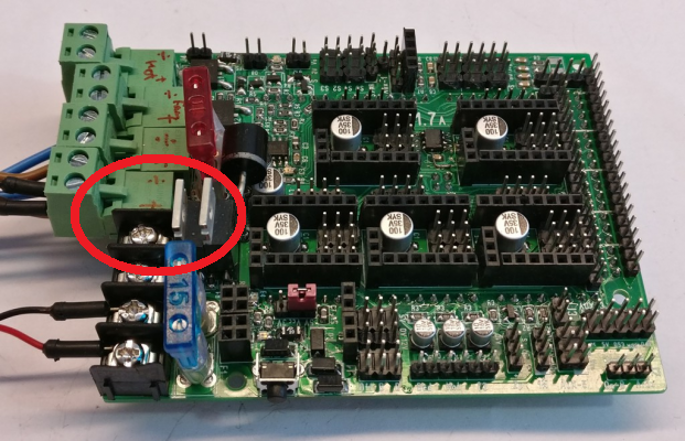
If someone uses a too long wire for the terminal, it could make contact with the bare back of the MOSFET.
If someone uses a too long wire for the terminal, it could make contact with the bare back of the MOSFET.
|
Re: New RAMPS design July 08, 2018 05:00AM |
Registered: 9 years ago Posts: 93 |
|
Re: New RAMPS design July 08, 2018 12:53PM |
Registered: 14 years ago Posts: 140 |
Quote
o_lampe
I see a potential problem there:
[attachment 105974 bf_800x400.png]
If someone uses a too long wire for the terminal, it could make contact with the bare back of the MOSFET.
You are quite right.
But as luck would have it, that terminal pin is directly connected to the back of the mosfet. This is not at all clear from the pictures, so I had to go and check in the pcb layout software.
This photo shows that only one screw section would likely have this potential issue. Only, as luck would have it, it turns out to not be an issue.
But thank you for pointing out a potential cause for (frequent) errors.
Edited 1 time(s). Last edit at 07/08/2018 12:53PM by MrAlvin.
|
Re: New RAMPS design July 08, 2018 01:19PM |
Registered: 14 years ago Posts: 140 |
Quote
boelle
yeah, i would have crimped on a ferrule
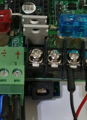
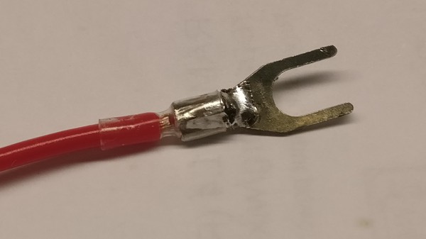
I agree. This kind of screw terminal is terrible, if only used with a wire-end sort of showed under the screw-plate.
I highly recommend using one of those y-shaped crimp-on wire connectors
This one is both crimped (for strength), soldered (for corrosion prevention) and shrink wraped (for alleviating the bending forces on the exposed wire)
And remember to get the narrow design (<4mm wide) of the y-fork crimp connector (there seems to a 3.2mm version that works well, or for 16-18 awg wire), as the 7.62mm pin space on these screw terminals are kind of "short" for this type of screw terminal. This style of screw terminal also comes in a 8.5mm (still 20A) and 9.5mm (25-30A) versions.
Other designs of screw terminals can be used either way; with the wire directly inserted into the screw terminal, or adding some kind of crimp on the end, to make the wire end stronger.
But this kind of screw terminal connector were the only pcb-style ones that that would show up (on the first page of show-lowest-prices-first) of an ebay search, for 20A screw terminals.
I often use ebay to find inspiration for parts or components, as it is an interesting tool to get an indication of the cheapest/okay option for any particular item, used in electronics.
Edited 2 time(s). Last edit at 07/08/2018 01:35PM by MrAlvin.
|
Re: New RAMPS design July 08, 2018 01:22PM |
Registered: 14 years ago Posts: 140 |
|
Re: New RAMPS design July 08, 2018 01:27PM |
Registered: 9 years ago Posts: 93 |
|
Re: New RAMPS design July 08, 2018 01:31PM |
Registered: 14 years ago Posts: 140 |
Quote
boelle
about the fork style terminals
i had the same problem with one of the 30A LED psu's
what i did was folding the 2 forks to it became a pin instead, cant quite remember how i did it it but it was easy enough
i basicly ended up with both forks on top of each other
Ah yes (when in a pinch) I can see that working too.
|
Re: New RAMPS design July 08, 2018 01:31PM |
Registered: 9 years ago Posts: 93 |
the same could be done with a ring terminal and you would end up with a kind of hook shape
i think i got the idea when i first crimped on ring terminals for the 230V to the LED psu, the rings would not fit either so i bend them a little but i put to much muscle in it and the ring folded completely on itself
i think i got the idea when i first crimped on ring terminals for the 230V to the LED psu, the rings would not fit either so i bend them a little but i put to much muscle in it and the ring folded completely on itself
|
Re: New RAMPS design July 08, 2018 01:36PM |
Registered: 9 years ago Posts: 93 |
i think the perfect ones are these:
[www.cablecraft.co.uk]
or maybe these:
[www.cablecraft.co.uk]
i found them on this page: [www.cablecraft.co.uk]
[www.cablecraft.co.uk]
or maybe these:
[www.cablecraft.co.uk]
i found them on this page: [www.cablecraft.co.uk]
|
Re: New RAMPS design July 08, 2018 06:25PM |
Registered: 6 years ago Posts: 93 |
I don't use crimps if the pad under the screw is corrugated or ribbed.
The soft copper strands deform into the ribs for whole contact, and the rigid crimps do not.
Besides that, I prefer the mono-metal contact .vs a secondary unknown alloy (from the land of cadmium filled jewelry).
Just my $.02..
Interesting project!
The soft copper strands deform into the ribs for whole contact, and the rigid crimps do not.
Besides that, I prefer the mono-metal contact .vs a secondary unknown alloy (from the land of cadmium filled jewelry).
Just my $.02..
Interesting project!
|
Re: New RAMPS design July 09, 2018 04:12AM |
Registered: 9 years ago Posts: 93 |
|
Re: New new RAMPS design July 18, 2018 04:27PM |
Registered: 8 years ago Posts: 28 |
hey Guys, iḿ even later to the Party,
I had a fight with my Ramps 1.3 (worked well for some Years) and all the soldered extra wires repairs fixes etc since I upgraded to tmc2130 so i decided to get a new Board, i than found that "all" the tmc2130 bords are not in my budged or i would rewire a Ramps..
so i decided to redesign ramps 1.4.2 to "somthing ramps alike" just for me, and now that i am near finished found someone had the same idea..
ive got a Arduino mega shield with 6drivers, (all spi) 3heaters 2 servos and 6 "led/fan/whatever additions, at 60x130mm but no aux no display, as i never used any of that, i use octoprint and solderd in some extras like fans leds filament sensor etc.
what do you think? i would go and relese the files now that you ar alredy on it i dont Think im goint to order some prototypes and Wait for yours to be released... sound way more professional.
if anyone likes to have a Look: [github.com]
btw: this is still early beta, i currently try to eather add xternals to the space under the drivers Or ad motor conectors Back to Board
Edited 1 time(s). Last edit at 07/18/2018 04:28PM by kabelfrikkler.
|
Re: New new RAMPS design August 03, 2018 10:59AM |
Registered: 14 years ago Posts: 140 |
Hi kabelfrikkler, good to hear from you.
Interesting board. Very minimal. Minimal is always interesting, as it will keep the cost low.
Have you found a place where they will produce a cheap board if it is over 100mm on one of the sides?
To be able to produce cheap prototypes I did decide to stay within the confines of 100mm x 100mm. As 100mm x 100mm can be produced very low cost at several pcb manufactures. Because of import rules where I live, I need the cost to be less than us$12 + shipping. And this framework has basically been the reason why I have ended up with the major layout being the way it is now.
I would have liked to add one more stepper driver - and a few other extras - but it has proven difficult to "shoehorn" it into the confines of 10 x 10 cm and still keep it like a shield for the Arduino Mega layout.
It might however be doable if one were to put, for instance, all the mosfets on a separate board. But for this iteration of a RAMPS board I have chosen not to do so. But perhaps for a future version :-)
On an other note, I have had to take a break from the testing, as life got in the way. But hopefully I will now be able to dedicate some time to get this project moving again.
To hopefully limit the time span before a fully tested board is available, I have decided to order a batch of the version 1.7B boards. They are currently in production with seeedstudio, and could thus, possibly, be in my hands within some 10 days, or so.
Both small green fuses, some solder-in glass fuses and some "0603 very fast mini" fuses have also arrived, so I hope to be able to test those fuses before the 10 days are up.
|
Re: New new RAMPS design August 03, 2018 11:13AM |
Registered: 9 years ago Posts: 93 |
|
Re: New new RAMPS design August 03, 2018 11:15AM |
Registered: 9 years ago Posts: 93 |
btw @kabelfrikkler
are you good doing designs etc? if so what do you think about the current Ramps FD v2.3 design? [github.com]
maybe we could take something from there or be inspired from it
are you good doing designs etc? if so what do you think about the current Ramps FD v2.3 design? [github.com]
maybe we could take something from there or be inspired from it
|
Re: New RAMPS design August 20, 2018 11:42PM |
Registered: 5 years ago Posts: 1 |
Hi guys,
If it's not too late to make a suggestion, I recommend these connectors:
[www.digikey.com]
They are screwless terminals, similar to what we use which are mounted to DIN rail in industrial control panels. The beauty of these connectors is that they simply do not come loose, and there isn't any screw to strip out.
|
Re: New RAMPS design August 27, 2018 11:26AM |
Registered: 8 years ago Posts: 28 |
sorry im late, got some vacations and decidet to do it in the Basement, as its way to hot to Drive anywere cooler,
I orderd the prototypes of my design for ~45€ 10pcbs and thats 4layer PCB leedfree-.-.-- (sadly you cant order less.. ) they arrived in 3days and i alredy found like.. 3errors, but the printer is moving so its okay..
I will have a look at RAMPS FD but im not that good in designing as i thing as i keep having nois problems in my thermistors
as for qualety and price i can say that allpcb was very pleasing and i got all my parts (without screw connectors and TC2130 drivers for about 8€=)
how was the quality of the seestudio PCBs? and mostly: what quantetys and price range are we talking? ALLPCB would be more interesting if we (you) say to order 10/20pcs and all go and try and test them out.
[photos.app.goo.gl]
|
Re: New RAMPS design August 28, 2018 08:01AM |
Registered: 14 years ago Posts: 140 |
Quote
rootboy
Hi guys,
If it's not too late to make a suggestion, I recommend these connectors:
[www.digikey.com]
They are screwless terminals, similar to what we use which are mounted to DIN rail in industrial control panels. The beauty of these connectors is that they simply do not come loose, and there isn't any screw to strip out.
Hi rootboy.
Because of the 20A rating those connectors are indeed interesting options.
I do however wonder if they are best suited for solid core wires?
A stranded wire might be a bit difficult to push in under the spring? But I suppose one could solder the end. And because of the spring pressure, then the usual issue with soldered wires in screw terminals would not be relevant.
Either way; good to know those connectors exist. They are an interesting option.
Sorry, only registered users may post in this forum.


