New RAMPS design
Posted by MrAlvin
|
Re: New RAMPS design June 17, 2018 08:27PM |
Registered: 6 years ago Posts: 8 |
T'was a typo - wrt Extruders; I'm just pointing out there are several use cases where multiply more extruders and/or Heads are the norm ; i.e CNC+Lazer+Ext ruder also is a relatively common setup.
I am fully aware it's not a shield. But out of the boards on my desk right now
3 are Arduino Nano style pinouts (esp8266 / esp32 lolins)
4 are Arduino Uno (1 espduino and 3 d1 r32 esp32 in uno formfactor (they actually have additional pins not on headers tho)
1 Is Nucleo 144 pin - which is uno'ish compat but all vertical rather than horizontal
My only Mega(ish) boards are Teensy/MicroPicos on board various custom pcb's
-- Am just pointing out that perhaps moving on from a Mega style shield is due (pun intended) - especially considering that most of the newer designs can do driver+extruder etc with a fair deal less pins than a Mega can. Maybe it's reasonable to design something more 'breadboard' than 'shield' like.
Edited 1 time(s). Last edit at 06/17/2018 08:30PM by aenertia.
|
Re: New RAMPS design June 17, 2018 08:38PM |
Registered: 9 years ago Posts: 93 |
hehe, this is a shield :-P
but i know what you mean, either a board that can connect in breadboard style or different versions that can stack on top og the MCU
but i agree partly with going away from mega.... 8 bit has it limits and 3d printing is always pushing the limits. that is why i suggested something like the teensy, it runs faster than due and has an FPU build in
on the other hand it could be nice to be able to get the board now and then upgrade the MCU later, that is good for poor people :-D
|
Re: New RAMPS design June 17, 2018 08:41PM |
Registered: 6 years ago Posts: 8 |
|
Re: New RAMPS design June 17, 2018 08:54PM |
Registered: 9 years ago Posts: 93 |
|
Re: New RAMPS design June 17, 2018 11:12PM |
Registered: 6 years ago Posts: 8 |
[esp-idf.readthedocs.io]
tl;dr 6 Analog - 44 useable total (although you can coax another 6 from it if you are brave)
Teensy 3.6 has 21 -
But you can use any of the 44 pins as PWM - and they can all be software defined on the ESP32 - likewise it has 2 full HW SPI - the teensy only has 1, The ESP also has a secondary ULP core which could be useful potentially as well as HW Crypto lacking on the teensy.
|
Re: New RAMPS design June 17, 2018 11:17PM |
Registered: 6 years ago Posts: 8 |
|
Re: New RAMPS design June 18, 2018 08:26PM |
Registered: 14 years ago Posts: 140 |
I am very glad to see that issues are being discussed and looked into. 
Please keep it up
A few random notes/comments as seen from my (current) perspective:
- While I agree that the Due is not the fastest 32 bit option out there, it is a natural upgrade path from a Mega. And the RAMPS board was always meant to be able to start/run on a Mega. So to continue that tradition, so can this board.
I see that Sparkfun has the Due in stock
- As this version of the RAMPS board it meant to be able to be use at both 5V and 3V logic levels, it ought to be fairly easy to wire it to any of the more powerful MPUs that has been mentioned.
- I have not looked into how to use/run the TMC2208 drivers, but as that extra cfg pin (as part of those three extra holes on some TMC2xxx boards) is being connected to a MCU i/o pin, it should be possible to set up SoftSerial (or similar) to be able to do the serial communication with the TMC2208 board.
- As soon as I know that this design actually works, all the source documents/files I have will be made available, as I don't think it is wise to put out information (for general internet consumption) about hardware that is untested. Status is; that a first prototype batch has been ordered at seeed studios, and they should be with mein about a week or two.
I the mean time I will be working on schematics, BOM etc.

Please keep it up
A few random notes/comments as seen from my (current) perspective:
- While I agree that the Due is not the fastest 32 bit option out there, it is a natural upgrade path from a Mega. And the RAMPS board was always meant to be able to start/run on a Mega. So to continue that tradition, so can this board.

I see that Sparkfun has the Due in stock
- As this version of the RAMPS board it meant to be able to be use at both 5V and 3V logic levels, it ought to be fairly easy to wire it to any of the more powerful MPUs that has been mentioned.
- I have not looked into how to use/run the TMC2208 drivers, but as that extra cfg pin (as part of those three extra holes on some TMC2xxx boards) is being connected to a MCU i/o pin, it should be possible to set up SoftSerial (or similar) to be able to do the serial communication with the TMC2208 board.
- As soon as I know that this design actually works, all the source documents/files I have will be made available, as I don't think it is wise to put out information (for general internet consumption) about hardware that is untested. Status is; that a first prototype batch has been ordered at seeed studios, and they should be with mein about a week or two.
I the mean time I will be working on schematics, BOM etc.
|
Re: New RAMPS design June 18, 2018 09:05PM |
Registered: 9 years ago Posts: 93 |
quick one before bed time
marlin firmware supports both tmc2130 and 2208
for 2208 hard just have to give each driver 2 digital pins and marlin takes care of the rest
for 2130 only one pin is needed (cs line)
and yes its very smart not to relase files before you know things work etc.... just see what happend to Ramps-FD.... all the china factories started to flood the market with board even thou they had been warned that it was not a safe board. Now most people still thinks that Ramps-FD is unsafe etc
we dont want that to happen to Ramps
i too will get a due, they are easy enough to get hold of even in little Denmark
|
Re: New RAMPS design June 19, 2018 05:24AM |
Registered: 14 years ago Posts: 140 |
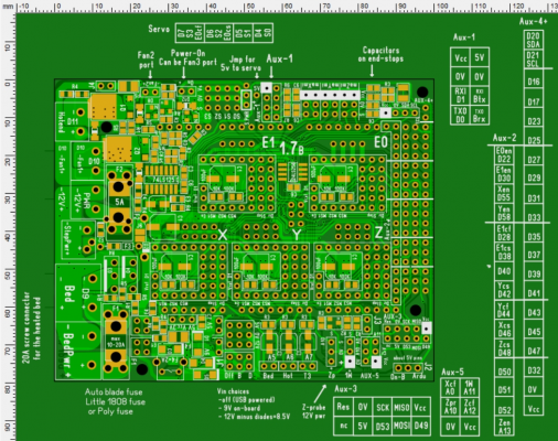
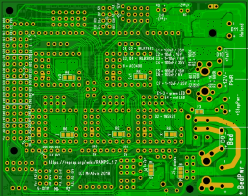
As I was preparing a pins_RAMPS_17.h file (working from the pins_RAMPS_14.h file) I discovered that there were some silkscreen errors on the boards (ver 1.7A) I already have ordered. These are now fixed for a ver 1.7B of the design.
As the TMC2208 is also mentioned in the pins....14.h file (and because of your talks about the TMC2208) I have now looked further into how the TMC2208 needs to be connected, and I have managed to add some solder jumpes, and space for the 1K resistors needed between the Rx and Tx Arduino pins leading to each driver. These solder jumpers and the resistors are added on the underside of the board, as the topside is basically really used up. Solder jumpers would probably also be a pain to access on the top side of the board anyway, so I think this buttom side add-on option will be okay.
I do not consider solder jumpers ideal, but I still consider them okay easy to use, and they make for cleaner wiring of the final board.
As it is possible to receive some status data via Diag1 pin on the TMC2130 board, I have wired this pin to an Arduino pin as well. This is why I talk about two extra i/o pins to the TMC2130.
It does however not seem like Marlin 1.x has support (yet) for getting the data from the Diag1 pin, but I think Tom Sanlander mentioned this option in his guide.
Anyway, already having reserved two extra pins for each driver, it has made it fairly easy to include/define Rx/Tx pins for the TMC2208 driver boards.
And I simply assumed that the Diag1 pin was used for the serial communication to the TMC2208 - my mistake, as the communication to the TMC2208 board happens to either MS3 or (on version 1.0 of the watterot TMC2208 board) to the "reset" pin (as defined by the original pololu A4983/A4988 boards).
So, using solder jumpers and one top-side jumper, it is now possible to easily config the RAMPS 1.7B board for use with the TMC2208 drivers as well.
|
Re: New RAMPS design June 19, 2018 07:12AM |
Registered: 14 years ago Posts: 140 |
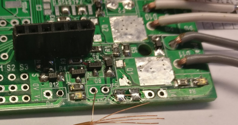
Here are pictures of the current state of the development, of the 1.7B board.
|
Re: New RAMPS design June 19, 2018 08:32AM |
Registered: 9 years ago Posts: 93 |
Solder jumpers are OK, and as you said there is no other place than the bottom side since the top side is taken and even if you could put them on top side they would be hard to reach
No stress :-D we want this one to be perfect before you let go of the files
With marlin i use the bugfix 2 branch
No stress :-D we want this one to be perfect before you let go of the files
With marlin i use the bugfix 2 branch
|
Re: New RAMPS design June 22, 2018 08:28AM |
Registered: 9 years ago Posts: 93 |
Quote
aenertia
Is Due event a consideration (it's not even produced anymore)
I just ordered 2 Due's from [store.arduino.cc], so yes they are still produced. They are just a very high demand item :-P
|
Re: New RAMPS design June 24, 2018 02:05PM |
Registered: 14 years ago Posts: 140 |
Today I have been testing.
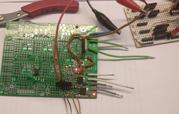
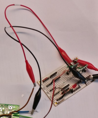
I have mainly been testing possible amp loads on the mosfets. In order to mainly test one link in the chain at a time (each mosfet), I have wired up a board this way:
I wired power lines to all sections from only one input source, by-passing all fuses.
I also soldered in wires, and not screw terminals, so I might try to exceed the limits of the screw terminals, and thus test to see if the PCB layout can handle higher amp loads. I will however need a different power supply to do those tests, so they will have to wait until I have got the 63A, 12V (old server power supply) connected properly.
I also shorted the 74ls125 chip, so I can test the mosfets with a 3.3V gate signal. Just to see what happens.
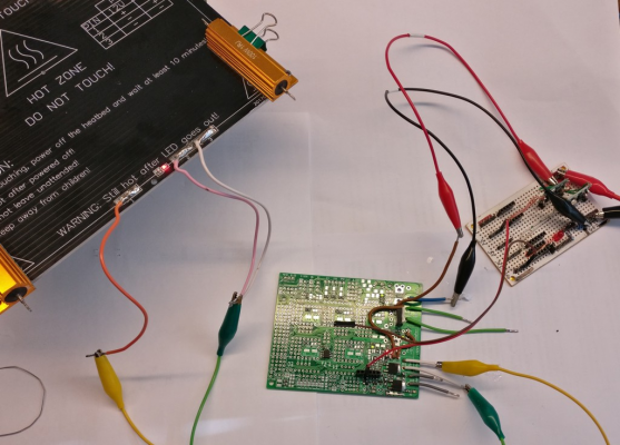
Here I am testing, using an alu heat-bed.
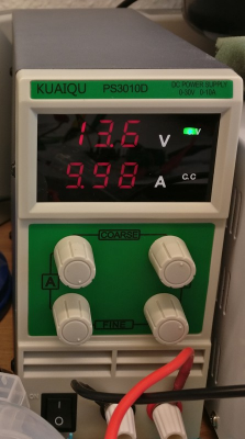
In order to get as close to a 10A load as possible, I turned up the voltage a little bit on the lab supply.
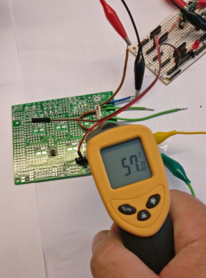
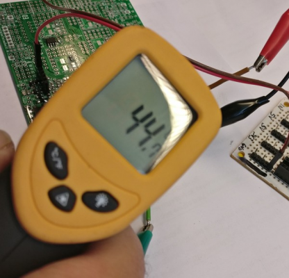
And this is a test of the SMD hot-end mosfet (IRLR8743). Not even the heat-bed mosfet (IRLB3034).
Using a IR thermometer is not really a very precise way of measuring temperature on such a small object, but this is what I had easily available. And this is the highest temperature I could get the thermometer to read after leaving it to sit for about 30 minutes.
The gate voltage ( Vgs) is 5V. When I tried it at 3.3V, on the hot-end SMD mosfet, it got very hot, very fast, so when used with a 32-bit (3.3V) MPU, then a buffer driver (or other voltage increasing setup) is very needed to get the most out of the IRLR8743 mosfet.
|
Re: New RAMPS design June 24, 2018 02:53PM |
Registered: 14 years ago Posts: 140 |
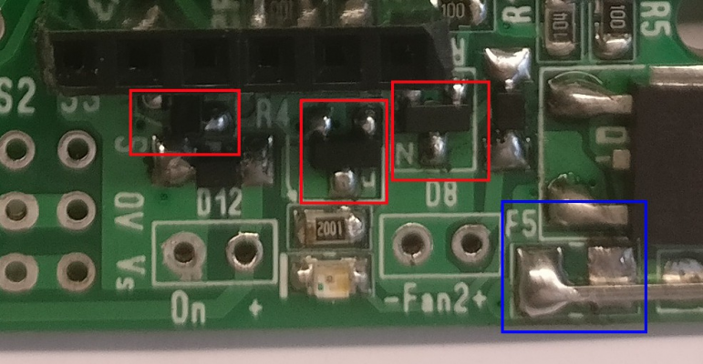
I also tested the small sot-23 housed mosfets (AO3400) - marked in red.
I originally planned to put a 2A poly fuse between the 12V rail and these small mosfets (Location for fuse marked in blue). But the tests did not turn out favorably for the poly fuse (nor the mosfets).
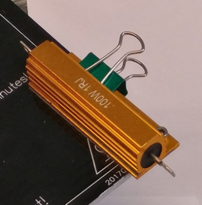
For this test (to do a 2A load) I used several of the 1 Ohm resistors attached to the heat-bed
To connect everything I often use these (enhanced) crocodile test wires.
I have replaced the original 24-26awg wires (capable of handeling 2-3A) with some 18awg (soldered in) wires. So these enhanced crocodile wires can easily handle the 10A max of my (current) lab-power-supply.
SOT-23 (AO3400) mosfet
My conclusion (so far) is, that these small mosfets can handle about 2.5A, even when controlled by a 3.3V (Vgs) signal. But only because the PCB layout is used to give as much cooling as possible.
Because of PCB cooling, my conclusion is also that the 2.5A limit is both for one mosfet, but also for the three of them combined. Or in other words, each channel can handle 2.5A but the total limit is also 2.5A, because they use the same copper to get cooled. So if all three of these small mosfets are driving loads, then each load should be less than 1A.
I hope this makes sense.
Poly fuses
When trying to short circuit the loads in the mosfets (something the polyfuse should current limit, and thus protect the mosfet), then the mosfets heats up faster than the polyfuse, so the mosfet fails (with a sharp small pop sound) before the poly fuse is able to limit the current. But at least the mosfets fails in a way that stops all current.
Further more, if the polyfuse is shorted, it dies. It does not react like a resetable-fuse, it acts like a "normal" fuse, and needs de-solderig and replacing. When shorted, it fails with a very noticable pop, and lets out some smoke.
So I wonder if I am doing something wrong, or if poly-fuses are not really meant to experience a complete short, but mainly will protect against a slow rising current.
Either way, I will test with other types of fuses as well.
Mainly a glass fuse, a 1808 little fuse and a 0603 smd fuse. And we will have to see how they respond, and see if they are faster than the mosfet, and thus will protect the mosfet.
|
Re: New RAMPS design June 24, 2018 03:43PM |
Registered: 14 years ago Posts: 140 |
I also tested the IRLB3034 mosfet.
Here is a temperature reading after about 12 minutes of operation. The temperature had been quite stable for more than 5 minutes
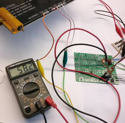
I had expected a lower temperature, for a 10A load, so I measured the voltage drop over the mosfet.
This cheap voltmeter (that I like because of its very small and handy size) says 58.2 mV between drain and source. At 10A this gives an internal resistance of about 6 milli Ohm. Which is a little higher than it ought to be.
But these components are basically the cheapest ebay options, so I can live with it being a little worse than from a brand name supplier.
Once I get my higher-amp-power-supply-option set up, I plan to test this with a small alu-fin heat sink, as well as with a parallel mounted mosfet option.
So we will have to see how that goes.
|
Re: New RAMPS design June 25, 2018 08:39AM |
Registered: 9 years ago Posts: 93 |
|
Re: New RAMPS design June 25, 2018 09:12AM |
Registered: 9 years ago Posts: 93 |
about the fuses... i think these 2 types would be best, cheap and easy to get
[www.thansen.dk]
[www.thansen.dk]
[www.thansen.dk]
[www.thansen.dk]
|
Re: New RAMPS design June 30, 2018 07:20AM |
Registered: 14 years ago Posts: 140 |
Quote
boelle
about the fuses... i think these 2 types would be best, cheap and easy to get
[www.thansen.dk]
[www.thansen.dk]
I have indeed designed the board so those (car) blade fuses can be used for the higher amp options.
Here I am testing, using blade fuses
I also tested a 1808 fuse, but I did not remember to get a picture of that.
This is some of what I discovered during my testing:
- fuses produce heat!!!
- at 50% of their rated limit they only get warm, and their heat contribution might be acceptable on a RAMPS board.
- at their rated limit they produce a noteworthy amount of heat.
- blade fuses are very slow fuses
- a 10A blade fuse will easily survive a 15A load for more than 1 hour, but will get hotter than 70*C
- a 1808 fuse also produces a noteworthy amount of heat when used at the limit of rated amp load
So my conclusion about fuses is;
- that I will want to limit the number of on-board fuses on my own printers, but
- will leave space for fuses in the current RAMPS 1.7B design.
|
Re: New RAMPS design June 30, 2018 08:01AM |
Registered: 14 years ago Posts: 140 |
Knowing:
- that I will want to limit the number of on-board fuses - because of their heat contribution to the entire board, and the electronics on the board.
- that (car) blade fuses are very slow fuses and are likely to survive running at +50% their rated value for hours on end (but will get very hot >70*C)
I wanted to get an indication of what kind of "over-sized" fuses could befitted, and still allow the mosfets to survive being shorted, long enough to make the fuses pop.
I tested using a 12V 30A supply, on a 20A fuse,
- but the supply would simply shut down the power supply, rather than blow the 20A fuse.
- the hot-end and fan mosfet (IRLR7843) did not survive the 20A test
- the heat-bed mosfet ( IRLB3034) survived the 20A-fuse-test just fine.
The hot-end and fan mosfet (IRLR7843) did however survive a 10A-blad-fuse-test just fine.
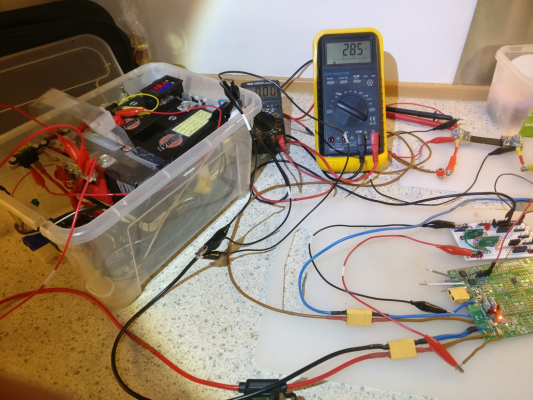
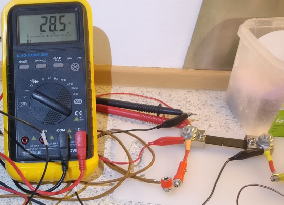
After swapping from the 12V, 30A power supply, to a set of LiFePO4 batteries, and swapping my 20A limited multi-meter with a 75A shunt resistor, then I was able to do some more testing on the limits of the heat-bed mosfets.
Beefed up test-setup
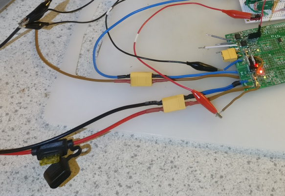
The batteries are rated to be able to deliver 270A each, though I have this setup procted by a 150A fuse.
Being able to test high-amp values
Using a multimeter to measure milli-volt over this shunt, it is possible to see how many amps are running through the shunt. This shunt is trimmed to show 15mV per Amp. So you need to divide the read-out on the multimeter by 1.5, to get the number in amps.
I set up the heat-bed to draw just around 19A (read 28.5mV on the meter ~= 19A) and protected the wires and circuits with a 30A blade-fuse. The fuse was mounted on the supply wire.
Then I shorted the wires at the heat bed.
And the heat-bed mosfet survived blowing the 30A blade fuse.
During the short, the highest number I saw on the multimeter was 69.8 (= 46.5A), and it took one-two seconds for the blade-fuse to blow.
This shows how I have moved the blade-fuse mount to the wires on the test board
And for convenience, some XT60 connectors are added to the mix.
|
Re: New RAMPS design June 30, 2018 08:19AM |
Registered: 14 years ago Posts: 140 |
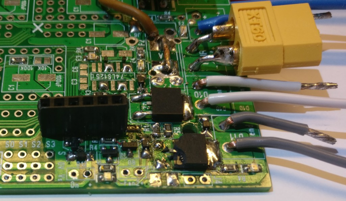
Replacing the hot-end and fan mosfets, after the 20A blade fuse test.
The black case material had become brittle, so when lifting each of the small legs on the TO-252 chip, then the legs and part of the casing broke off.
One mosfet removed
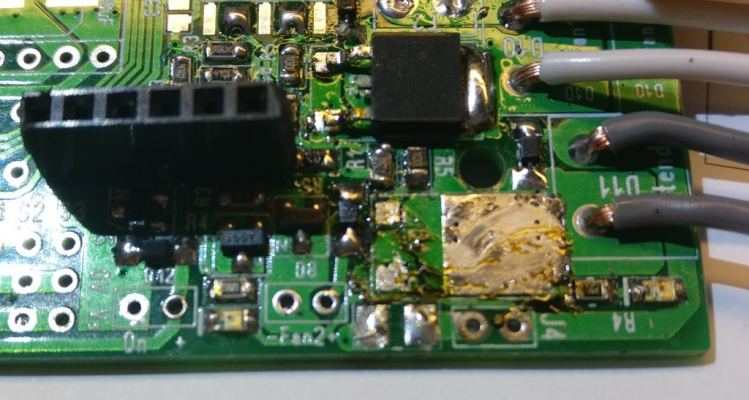
Both mosfets removed, and the surface cleaned using first some solder-wick wire. And some rubbing alcohol.
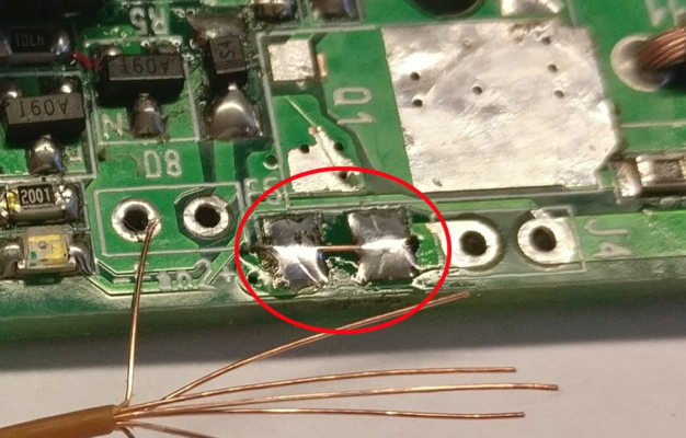
And illustrating how I will use a single strand of wire, to (hopefully) establish the weakest link of this 12V rail, leading to the AO3400 mosfets.
This wire will not protect the AO3400 mosfets, but a test shows that it will protect the PCB paths during a short-circuit condition.
|
Re: New RAMPS design June 30, 2018 09:35AM |
Registered: 9 years ago Posts: 93 |
|
Re: New RAMPS design July 01, 2018 02:29AM |
Registered: 8 years ago Posts: 5,232 |
|
Re: New RAMPS design July 01, 2018 03:33AM |
Registered: 14 years ago Posts: 140 |
Ah, good to know.Quote
o_lampe
Fast fuses are sand filled with a glass-housing.
This set of tests has taught me several new things about fuses, that I had not known or not payed much attention to before.
It is indeed. However, because of the amp load/level, there is a need for a certain (typically high) level of copper going to and from the fuse.Quote
o_lampe
Leading heat away from the fuse into the PCB is slowing down the fuse.
Ah yes, I remember this comment. Now I am beginning to see the merits of why to do thisQuote
o_lampe
I repeat my earlier proposal: use inline fuses and save the PCB space for other stuff.

|
Re: New RAMPS design July 01, 2018 03:53AM |
Registered: 8 years ago Posts: 5,232 |
|
Re: New RAMPS design July 01, 2018 04:09AM |
Registered: 14 years ago Posts: 140 |
So far these experiments has indeed lead me to conclude that fuses are useful for protecting wires (and pcb traces) against overheating.Quote
boelle
I guess the fuses are only good for shorts?
My wish was, that fuses could also be used to protect the mosfets from blowing. And so far it seems like the slow reacting fuses are not very suitable for protecting mosfets in small casings from overheating. Or rather mosfets with even 4 milli ohm resistance seems to heat up (and blow) much faster than the normal/slow reacting fuses.
So far I have not had really fast fuses available for testing, but I have some on order, so I will test them at a later date.
They do indeed take up more space.Quote
boelle
i know that for the cylinder shape glass fuses they come in a fast and slow acting type, but would they not take up more space?
So for now, I will just leave things (about fuses) as they are, and move on to test other details on the board. And (for now) I will live with the fact that the on-board fuses mainly protect the pcb traces from failing during a short circuit condition.
What I have however done (for version 1.7B ) is to enhance the size of the soldering pads for the mosfets, so it will be less likely that a pad becomes un-glued during the replacement operation of a failed mosfet.
I have also added more vias in the path of power rails, as this testing also has shown that a single via becomes the "fuse" during those about 2 seconds it takes for a blade fuse to blow during a short circuit condition.
|
Re: New RAMPS design July 02, 2018 03:40PM |
Registered: 11 years ago Posts: 1,049 |
Outstanding thread
Bravo on New RAMPS
?? Where does the arduino plug in ??
MOSFET
Why not MOSFET with large tab off the PCB, that can be thermally synced with radiator?
Would over rating the MOSFET protect it or just lead people to draw more on it?
If you need high current control --- do it off the main board with control from main board?
What is fate of MrAlvin-RAMPS 1.7 --- MrAlvin / Kimchi electronics production?

|
Re: New RAMPS design July 02, 2018 04:19PM |
Registered: 9 years ago Posts: 93 |
Quote
cozmicray
?? Where does the arduino plug in ??
like normal ramps... see pictures of board here: [reprap.org]
Quote
cozmicray
Why not MOSFET with large tab off the PCB, that can be thermally synced with radiator?
Would over rating the MOSFET protect it or just lead people to draw more on it?
problems are not so much the FET, its more that a fuse does not blow if you draw say 25A through a 20A Fuse, everything just gets hot
the only thing the fuse is good for is if you make a short circuit, and even if you use a fast acting fuse it might still not save the FET.
what makes the FET hot is if its turn on resistance is to high, so to get it run cool you just pick one with low resistance, they cost more thou
Quote
cozmicray
What is fate of MrAlvin-RAMPS 1.7
if you read above you would know that MrAlvin is testing it right now and making adjustments to design
|
Re: New RAMPS design July 02, 2018 04:22PM |
Registered: 9 years ago Posts: 93 |
So my guess is that the fuse will protect the board and not the FET if a short circuit happens
the best that we can is to pick a FET with very low resistance and to use connectors that is rated high enough and have low contact resistance
a connector with to high resistance will also just get hot and melt
the best that we can is to pick a FET with very low resistance and to use connectors that is rated high enough and have low contact resistance
a connector with to high resistance will also just get hot and melt
|
Re: New RAMPS design July 03, 2018 07:26AM |
Registered: 14 years ago Posts: 140 |
Thank youQuote
cozmicray
Outstanding thread
Bravo on New RAMPS

Under neath this board, like previous RAMPS boards, and like any Arduino shield.Quote
cozmicray
?? Where does the arduino plug in ??
For typical use, it is not necessary to do that. Otherwise it is a good idea, and a design option that is often being used.Quote
cozmicray
Why not MOSFET with large tab off the PCB, that can be thermally synced with radiator?
Perhaps. For typical use (a 20 x 20 cm heat bed) this board should easily be able to handle it. For some of the larger (and newer) heat-bed sizes, it should still be able to keep up with most of them. My goal has been to be able to handle a 20A heat-bed, with some headroom. So if a heat-bed draws 23A it should still be abler to work just fine. At that point the screw terminal will however become the bottle neck.Quote
cozmicray
Would over rating the MOSFET protect it or just lead people to draw more on it?
Yes, that would be the recommended path to choose.Quote
cozmicray
If you need high current control --- do it off the main board with control from main board?
Well, no fate has been decided yetQuote
cozmicray
What is fate of MrAlvin-RAMPS 1.7 --- MrAlvin / Kimchi electronics production?
 So far it is all in the prototype (and testing) stage.
 I am not planning on making money from this endeavor, so I have no immediate plans of any scale of production.
To help those who can not (or do not want to) assemble their own boards, I may very well do a small production run, and probably offer up (a limited number of) boards on ebay (or similar).
But once I know everything works, all files will be made available. At that point, it is anyones guess what will happen.
For right now, I order 10 PCBs every time I am ready to test an iteration of the design. So if you (or anyone else) would like to do their own testing, your are welcome to contact me, to get one of these prototype boards.
|
Re: New RAMPS design July 03, 2018 11:47AM |
Registered: 9 years ago Posts: 93 |
Sorry, only registered users may post in this forum.
