How to wire galvos (ILDA) up with Ramps 1.4?
Posted by Blacksheep
|
How to wire galvos (ILDA) up with Ramps 1.4? June 16, 2018 06:20AM |
Registered: 5 years ago Posts: 4 |
Hi there,
I got a nice scanner head (not the china 70 Euro ones) with a f 430 Theta lens. Using an Arduino Mega & an additional bipolar circuit with a 12 bit DAC and 2 opamps I am able to paint nice and clear pictures.
Now I want to marry the galvos with RAMPs but I don't have any clue how to wire it up. What I basically need is to get the -5/GND/+5 signal (for Y and X axis) from the RAMPS board to control the galvos.
Found a lot of helpful information in the board about using RAMPS with galvos but not that specific information. In some therads there was said that the signal was taken from the Arduino via SPI (what my setup does too). But once the RAMPS board is connected to the Arduino all connections are blocked by the shield. Any documentation I missed?
EDIT: I noticed the SPI port on the RAMPS board but it is being used by the adapter for the display.
I am working on a SLA Printer with a build volume of 300x300x1000 mm
Regards
Blacksheep
Edited 2 time(s). Last edit at 06/16/2018 06:45AM by Blacksheep.
|
Re: How to wire galvos (ILDA) up with Ramps 1.4? June 16, 2018 07:11AM |
Admin Registered: 13 years ago Posts: 7,000 |
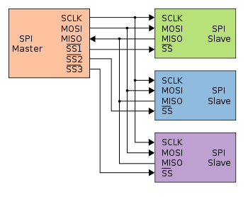
SPI is a bus... you connect the 3 line to all devices
The only thing you need is a dedicated SS pin for each device...
The only thing you need is a dedicated SS pin for each device...
|
Re: How to wire galvos (ILDA) up with Ramps 1.4? June 16, 2018 07:29AM |
Admin Registered: 13 years ago Posts: 7,000 |
ramps has support for steppers that have step/direction lines, it knows nothing of controlling a dac
you could put a nano on each axis and to count the pulses and watch the direction line and convert that to analog...
I suspect trying to using a ramps is not the right approach,,
maybe take a look at the LAMPS project [github.com]
Edited 1 time(s). Last edit at 06/16/2018 07:30AM by Dust.
you could put a nano on each axis and to count the pulses and watch the direction line and convert that to analog...
I suspect trying to using a ramps is not the right approach,,
maybe take a look at the LAMPS project [github.com]
Edited 1 time(s). Last edit at 06/16/2018 07:30AM by Dust.
|
Re: How to wire galvos (ILDA) up with Ramps 1.4? June 16, 2018 12:42PM |
Registered: 5 years ago Posts: 4 |
Thank you for the feedback.
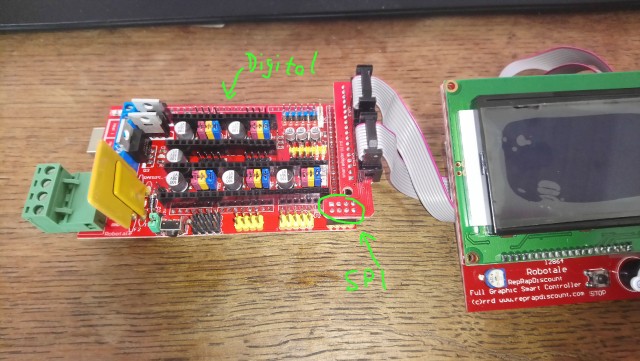
So in theory I could solder the SCLK,MOSI and MISO of my DAC PCB to the connectors of the display adapter (circle) and the SS pin to one digital connector and control via Marlin the assignment?
[preview.ibb.co]
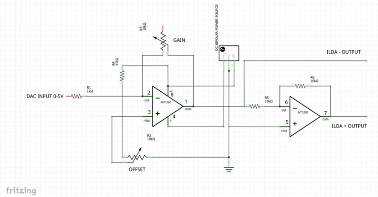
I unfortunately did not find a description which digital pin's are already used by the RAMPS board. By the way, this circuit (for each axis) is being used for the converter:
I already have seen the LAMPS project but there was no update since 5 years so the project looks dead. For a programmer with basic electronics skills a showstopper.
Edited 2 time(s). Last edit at 06/16/2018 12:56PM by Blacksheep.
Sorry, only registered users may post in this forum.


