Ramps 1.4 with TMC2209 Stallguard?
Posted by Ohmarinus
|
Ramps 1.4 with TMC2209 Stallguard? October 07, 2020 10:39AM |
Admin Registered: 11 years ago Posts: 3,096 |
Hi, I'm having some issues finding the correct information on the web concerning the combination of Ramps 1.4 and TMC2209 stepper drivers.
These drivers are supposed to have UART and also offer Stallguard4, now I want to do this sensorless homing because this machine I've built is simply designed for it.
But I haven't been able to find anyone referencing how this is to be done. I did work with TMC2209 drivers before on an SKR 1.4 board and it works wonderfully, but for the Ramps 1.4 I simply have no idea where to start. Finding no others using this combination but only two other people on the Marlin Github I started to doubt if this is even possible, but apparently they solved the issues (just didn't share the howto) and it should be possible.
Well, if anyone could point me in the correct direction that would be great. I know the diag pin is used to communicate a stall-detection to the endstop pin, but have no clue how to wire this up.
Second, I also have used TMC2208's on ramps and had to solder a special cable going to the Rx and Tx inputs with one needing a resistor in between. Used Dust mentioned somewhere that this in fact isn't even needed and that Rx and Tx can be done through a single wire. I just couldn't find it back and have no clue how to set this up as well.
The drivers I'm using are the v1.2 TMC2209 drivers by BigTreeTech. The Ramps board just being a simple generic Ramps with a real Mega underneath. I'm using an LCD screen so using SPI is out of the question, however since TMC2209 uses UART I don't see any problems there.
http://www.marinusdebeer.nl/
|
Re: Ramps 1.4 with TMC2209 Stallguard? October 07, 2020 12:58PM |
Registered: 6 years ago Posts: 265 |
To control 2209s with UART on a RAMPS you can use one pin to control up to four drivers. You need to select a pin that is interrupt-capable, for example D21 or D20 on the I2C connector. You'll need to make a "hydra" cable with one input and multiple outputs. On my setup I have one pin controlling X, Y and Z, and another controlling E0 and Z2 (connected to the E1 driver).
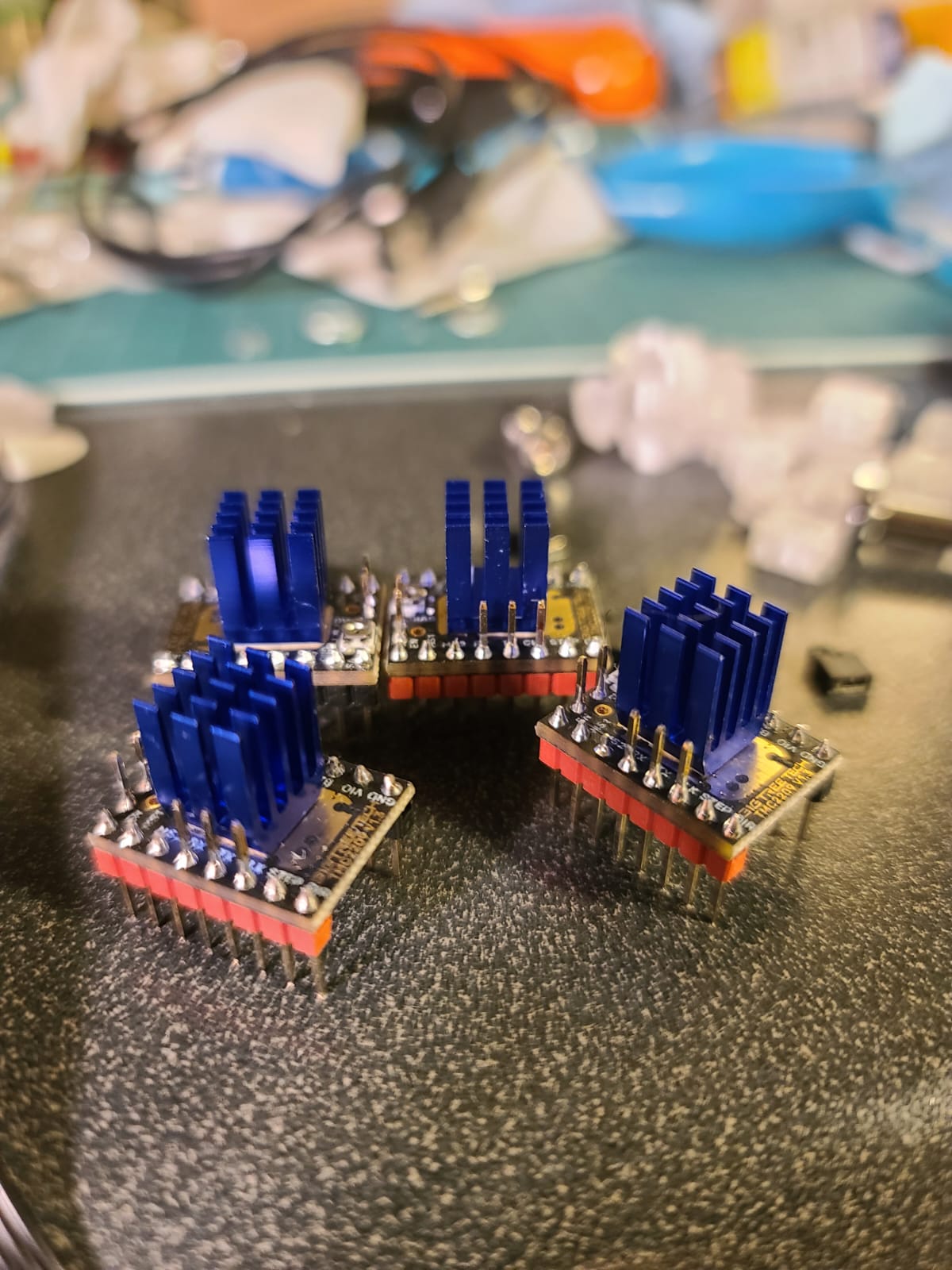
The driver has a set of two pins on the short side and three pins on the long side protruding above the board. The UART pin is the first pin on the long side (the one closest to the EN pin, what would be MS3 on an A4988). Connect your wiring harness to that pin on each driver. Remove the MS3 jumpers on all drivers, and use MS1 and MS2 to set the address of the driver. No jumper on either MS1 or MS2 is address 0, MS1 jumpered and no jumper on MS2 is 1, MS2 jumpered and no jumper on MS1 is 2, and both jumpers is 3. Each driver on the same pin needs a unique address.
At the end of your Configuration_adv.h, set the TX and RX pins for your drivers. For example:
// For TMC drivers
#define X_SERIAL_TX_PIN  21
#define X_SERIAL_RX_PIN  21
#define Y_SERIAL_TX_PIN  21
#define Y_SERIAL_RX_PIN  21
#define Z_SERIAL_TX_PIN  21
#define Z_SERIAL_RX_PIN  21
#define E0_SERIAL_TX_PIN  20
#define E0_SERIAL_RX_PIN  20
#define Z2_SERIAL_TX_PIN  20
#define Z2_SERIAL_RX_PIN  20
and change the _SLAVE_ADDRESS values according to the addresses you selected for the drivers (the following is my configuration):
 #define  X_SLAVE_ADDRESS 0
  #define  Y_SLAVE_ADDRESS 1
  #define  Z_SLAVE_ADDRESS 2
  #define X2_SLAVE_ADDRESS 0
  #define Y2_SLAVE_ADDRESS 0
  #define Z2_SLAVE_ADDRESS 1
  #define Z3_SLAVE_ADDRESS 0
  #define Z4_SLAVE_ADDRESS 0
  #define E0_SLAVE_ADDRESS 0
  #define E1_SLAVE_ADDRESS 0
  #define E2_SLAVE_ADDRESS 0
  #define E3_SLAVE_ADDRESS 0
  #define E4_SLAVE_ADDRESS 0
  #define E5_SLAVE_ADDRESS 0
  #define E6_SLAVE_ADDRESS 0
  #define E7_SLAVE_ADDRESS 0
I don't use StallGuard since I always see people have problems with it so I can't help you with that part.
|
Re: Ramps 1.4 with TMC2209 Stallguard? October 07, 2020 02:04PM |
Admin Registered: 11 years ago Posts: 3,096 |
Quote
MMcLure
To control 2209s with UART on a RAMPS you can use one pin to control up to four drivers. You need to select a pin that is interrupt-capable, for example D21 or D20 on the I2C connector. You'll need to make a "hydra" cable with one input and multiple outputs. On my setup I have one pin controlling X, Y and Z, and another controlling E0 and Z2 (connected to the E1 driver).
The driver has a set of two pins on the short side and three pins on the long side protruding above the board. The UART pin is the first pin on the long side (the one closest to the EN pin, what would be MS3 on an A4988). Connect your wiring harness to that pin on each driver. Remove the MS3 jumpers on all drivers, and use MS1 and MS2 to set the address of the driver. No jumper on either MS1 or MS2 is address 0, MS1 jumpered and no jumper on MS2 is 1, MS2 jumpered and no jumper on MS1 is 2, and both jumpers is 3. Each driver on the same pin needs a unique address.
At the end of your Configuration_adv.h, set the TX and RX pins for your drivers. For example:
// For TMC drivers
#define X_SERIAL_TX_PIN  21
#define X_SERIAL_RX_PIN  21
#define Y_SERIAL_TX_PIN  21
#define Y_SERIAL_RX_PIN  21
#define Z_SERIAL_TX_PIN  21
#define Z_SERIAL_RX_PIN  21
#define E0_SERIAL_TX_PIN  20
#define E0_SERIAL_RX_PIN  20
#define Z2_SERIAL_TX_PIN  20
#define Z2_SERIAL_RX_PIN  20
and change the _SLAVE_ADDRESS values according to the addresses you selected for the drivers (the following is my configuration):
 #define  X_SLAVE_ADDRESS 0
  #define  Y_SLAVE_ADDRESS 1
  #define  Z_SLAVE_ADDRESS 2
  #define X2_SLAVE_ADDRESS 0
  #define Y2_SLAVE_ADDRESS 0
  #define Z2_SLAVE_ADDRESS 1
  #define Z3_SLAVE_ADDRESS 0
  #define Z4_SLAVE_ADDRESS 0
  #define E0_SLAVE_ADDRESS 0
  #define E1_SLAVE_ADDRESS 0
  #define E2_SLAVE_ADDRESS 0
  #define E3_SLAVE_ADDRESS 0
  #define E4_SLAVE_ADDRESS 0
  #define E5_SLAVE_ADDRESS 0
  #define E6_SLAVE_ADDRESS 0
  #define E7_SLAVE_ADDRESS 0
I don't use StallGuard since I always see people have problems with it so I can't help you with that part.
Wow, this is exactly what I needed to know! Thank you so much. By the way, I've read that the solution to making Stallguard work is to lower the power to 200mA temporarily and raising the feedrate a bit instead of lowering it. I have yet to try it out because first I'm going to rewire my entire machine now that I've confirmed my setup works in its current setup but I have too many cables running around so I need to shorten some cables and reroute them a bit smarter (Ramps doesn't allow smart cable management very well, SKR 1.3/1.4 is much better suited for that task).
I honestly do not completely understand the slave address selection. You use Z2 for E1 but Z2 also is slave 1 just like your Y slave address? Can they share a slave address?
Ahhh, does it mean I have to use the jumper settings underneath the stepper driver to set the slave address, instead of setting the microstepping mode?
Found the schematic here:
[github.com]
Edited 2 time(s). Last edit at 10/07/2020 02:17PM by Ohmarinus.
http://www.marinusdebeer.nl/
|
Re: Ramps 1.4 with TMC2209 Stallguard? October 07, 2020 04:49PM |
Registered: 6 years ago Posts: 265 |
The way slave addresses work is that all drivers connected to the same pin need to have different slave addresses, but drivers on different pins can share a slave address. The combination of pin and slave address needs to be unique for each driver.
So I can use the same slave address for Y and Z2 because they are on different pins (21 and 22). The default configuration has all drivers sharing address 0 and using different pins, but I like to take advantage of the address feature to free pins for other uses (more important when you're using Re-ARM instead of ATMega2650 since Re-ARM doesn't have all of the pins provided by the ATMega).
If you are using a UART connection to your 2209s then the jumpers are used to configure the slave address, and micro steps are set via Configuration_adv.h. Look for the code section that starts with
#if HAS_TRINAMIC_CONFIGand set your micro steps (and current) there. That's also where you can set a different current for sensorless homing.
|
Re: Ramps 1.4 with TMC2209 Stallguard? October 08, 2020 03:52AM |
Admin Registered: 11 years ago Posts: 3,096 |
Quote
MMcLure
The way slave addresses work is that all drivers connected to the same pin need to have different slave addresses, but drivers on different pins can share a slave address. The combination of pin and slave address needs to be unique for each driver.
So I can use the same slave address for Y and Z2 because they are on different pins (21 and 22). The default configuration has all drivers sharing address 0 and using different pins, but I like to take advantage of the address feature to free pins for other uses (more important when you're using Re-ARM instead of ATMega2650 since Re-ARM doesn't have all of the pins provided by the ATMega).
If you are using a UART connection to your 2209s then the jumpers are used to configure the slave address, and micro steps are set via Configuration_adv.h. Look for the code section that starts with
#if HAS_TRINAMIC_CONFIGand set your micro steps (and current) there. That's also where you can set a different current for sensorless homing.
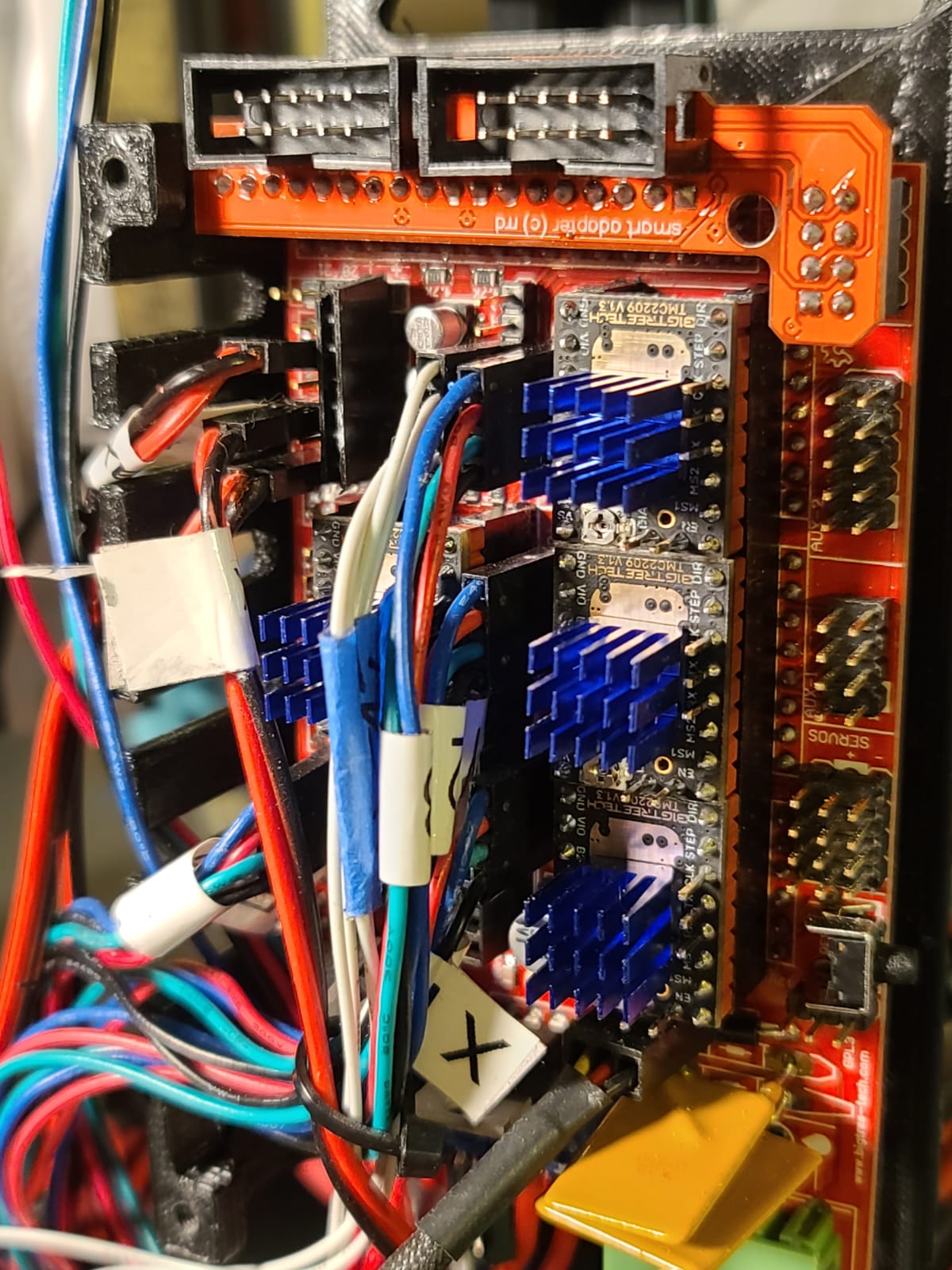
Exactly, I have used TMC2209 and TMC2208 before with great success, I am very familiar with the TMC settings, but never dove into the I2C options. This is great!!! My previous ramps build was completely crowded with all the wires going from each stepper to the Rx and Tx connections. Thanks for sharing this. I have meanwhile figured out how to get it all connected. Reworking the wiring right now to allow for better airflow. Will update once it's working. I'll also have a go at Stallguard and will share my findings. Thank you so far!

http://www.marinusdebeer.nl/
|
Re: Ramps 1.4 with TMC2209 Stallguard? October 08, 2020 10:47AM |
Admin Registered: 11 years ago Posts: 3,096 |
I sadly get:
These are my settings:
X has MS1 jumpered and Y has MS2 jumpered. I have measured the 'hydra' cable and it does connect to pin 21 on the I2C connector.
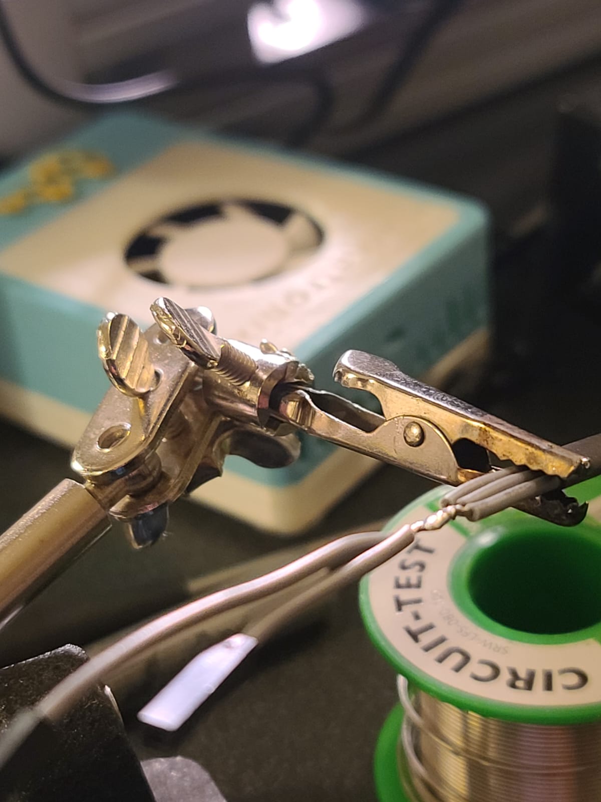
I have connected the other side of the hydra cable to the left-most pin on the front side of the driver, 'pin 4' or the PDN pin for UART.
Edited 1 time(s). Last edit at 10/08/2020 11:10AM by Ohmarinus.
http://www.marinusdebeer.nl/
Driver registers:
		X	0x00:00:00:00	 Bad response!
		Y	0x00:00:00:00	 Bad response!
Testing X connection... Error: All LOW
Testing Y connection... Error: All LOW
These are my settings:
#define  X_SLAVE_ADDRESS 1
  #define  Y_SLAVE_ADDRESS 2
  #define  Z_SLAVE_ADDRESS 0
  #define X2_SLAVE_ADDRESS 0
  #define Y2_SLAVE_ADDRESS 0
  #define Z2_SLAVE_ADDRESS 0
  #define Z3_SLAVE_ADDRESS 0
  #define Z4_SLAVE_ADDRESS 0
  #define E0_SLAVE_ADDRESS 0
  #define E1_SLAVE_ADDRESS 0
  #define E2_SLAVE_ADDRESS 0
  #define E3_SLAVE_ADDRESS 0
  #define E4_SLAVE_ADDRESS 0
  #define E5_SLAVE_ADDRESS 0
  #define E6_SLAVE_ADDRESS 0
  #define E7_SLAVE_ADDRESS 0

  // For TMC drivers
#define X_SERIAL_TX_PIN  21
#define X_SERIAL_RX_PIN  21
#define Y_SERIAL_TX_PIN  21
#define Y_SERIAL_RX_PIN  21
X has MS1 jumpered and Y has MS2 jumpered. I have measured the 'hydra' cable and it does connect to pin 21 on the I2C connector.
I have connected the other side of the hydra cable to the left-most pin on the front side of the driver, 'pin 4' or the PDN pin for UART.


Edited 1 time(s). Last edit at 10/08/2020 11:10AM by Ohmarinus.
http://www.marinusdebeer.nl/
|
Re: Ramps 1.4 with TMC2209 Stallguard? October 08, 2020 01:57PM |
Registered: 6 years ago Posts: 265 |
Your connections and configuration look right to me.
Assuming these are the same drivers that worked on the SKR it's unlikely that the PDN pins are not connected correctly, though it wouldn't hurt to examine the bottom of the driver and make sure the PDN jumper (it's hard to see - a tiny black "0 ohm" surface mount resistor) is in the right place. All of the drivers I've received from BTT have had the correct jumper. It might be easier to measure continuity between the pin and the center pad of the PDN jumper to make sure the jumper is correct. Also check that the second pin does not have continuity to the center pad of the jumper.
I personally also cut all of the bottom portions of the pins that protrude above the board (the three on the long side and the two on the short side). However, I don't think this actually makes a difference to the behavior of the drivers, since removing MS3 means that there is no connection to the first PDN pin, the second PDN pin should be open circuit on the driver board, and the RAMPS shorts the CLK pin to the second PDN pin which is open circuit.
I honestly don't know why it's not working for you. The configuration I provided is similar to the one I use, except that my pins are P0_02 and P0_03 on my Re-ARM.
You might try enabling PINS_DEBUGGING and sending an M43 to make sure nothing else is conflicting with your use of pins 21 and 20.
Wait - how are you powering your RAMPS? Via USB or via a power supply? If you're backpowering the RAMPS via USB and don't have the main power supply powered up then you will always get ALL LOW - the TMC drivers require full power to work.
|
Re: Ramps 1.4 with TMC2209 Stallguard? October 08, 2020 03:14PM |
Admin Registered: 11 years ago Posts: 3,096 |
You bet I tried it with 12v on  like I said, I've got TMC drivers on three other machines as well. But it's good to ask, some ppl might forget.
The resistors also seem to be present. I will try the pin debug mode to see if anything comes up. But before I do that I'll try pin 20 instead of 21.
I'm using Marlin 2.0.6.1 I just hope there's no issue with that version. It was a fresh install and everything works. I tried resetting eeprom, turning off/on the machine, tried moving the axes before a M122, made no difference. The machine homes fine btw.
Thanks for the advice, so it's clear the pins are not conflicting and that everything is as it should be. However, the TMC2209's are still reporting an error of not being connected. Which is really weird. I learned a lot of new stuff again! I hope we can find out what's causing the issues.
Edited 3 time(s). Last edit at 10/08/2020 03:29PM by Ohmarinus.
http://www.marinusdebeer.nl/
like I said, I've got TMC drivers on three other machines as well. But it's good to ask, some ppl might forget.The resistors also seem to be present. I will try the pin debug mode to see if anything comes up. But before I do that I'll try pin 20 instead of 21.
I'm using Marlin 2.0.6.1 I just hope there's no issue with that version. It was a fresh install and everything works. I tried resetting eeprom, turning off/on the machine, tried moving the axes before a M122, made no difference. The machine homes fine btw.

PIN:   0   Port: E0        RXD0                                   protected
PIN:   1   Port: E1        TXD0                                   protected
PIN:   2   Port: E4                               Input  = 1                           TIMER3B   PWM:     0    WGM: 1    COM3B: 1    CS: 3    TCCR3A: 1    TCCR3B: 3    TIMSK3: 0
PIN:   3   Port: E5        X_MIN_PIN                              protected
.                          X_STOP_PIN                             protected
PIN:   4   Port: G5        FIL_RUNOUT_PIN                         Input  = 1    TIMER0B   PWM:   128    WGM: 3    COM0B: 3    CS: 3    TCCR0A: 3    TCCR0B: 3    TIMSK0: 5   compare interrupt enabled   overflow interrupt enabled
.                          SERVO3_PIN                             Input  = 1    TIMER0B   PWM:   128    WGM: 3    COM0B: 3    CS: 3    TCCR0A: 3    TCCR0B: 3    TIMSK0: 5   compare interrupt enabled   overflow interrupt enabled
PIN:   5   Port: E3        SERVO2_PIN                             Input  = 1    TIMER3A   PWM:     0    WGM: 1    COM3A: 1    CS: 3    TCCR3A: 1    TCCR3B: 3    TIMSK3: 0
PIN:   6   Port: H3        SERVO1_PIN                             Input  = 1    TIMER4A   PWM:     0    WGM: 1    COM4A: 1    CS: 3    TCCR4A: 1    TCCR4B: 3    TIMSK4: 0
PIN:   7   Port: H4                               Input  = 0                           TIMER4B   PWM:     0    WGM: 1    COM4B: 1    CS: 3    TCCR4A: 1    TCCR4B: 3    TIMSK4: 0
PIN:   8   Port: H5        HEATER_BED_PIN                         protected
.                          RAMPS_D8_PIN                           protected
PIN:   9   Port: H6        FAN_PIN                                protected
.                          RAMPS_D9_PIN                           protected
PIN:  10   Port: B4        HEATER_0_PIN                           protected
.                          RAMPS_D10_PIN                          protected
PIN:  11   Port: B5        SERVO0_PIN                             Input  = 1    TIMER1A   PWM:  2000    WGM: 4    COM1A: 0    CS: 2    TCCR1A: 0    TCCR1B: 10    TIMSK1: 2   non-standard PWM mode   compare interrupt enabled
PIN:  12   Port: B6                               Input  = 1                           TIMER1B   PWM:     0    WGM: 4    COM1B: 0    CS: 2    TCCR1A: 0    TCCR1B: 10    TIMSK1: 2   non-standard PWM mode
PIN:  13   Port: B7        LED_PIN                                Input  = 0    TIMER0A   PWM:     0    WGM: 3    COM0A: 3    CS: 3    TCCR0A: 3    TCCR0B: 3    TIMSK0: 5   overflow interrupt enabled
 .                  TIMER1C is also tied to this pin                  TIMER1C   PWM:     0    WGM: 4    COM1C: 0    CS: 2    TCCR1A: 0    TCCR1B: 10    TIMSK1: 2   non-standard PWM mode
PIN:  14   Port: J1        Y_MIN_PIN                              protected
.                          Y_STOP_PIN                             protected
PIN:  15   Port: J0                               Input  = 1
PIN:  16   Port: H1        LCD_PINS_RS                            Output = 1
PIN:  17   Port: H0        LCD_PINS_ENABLE                        Output = 0
PIN:  18   Port: D3        Z_MIN_PIN                              protected
.                          Z_STOP_PIN                             protected
PIN:  19   Port: D2                               Input  = 0
PIN:  20   Port: D1        X_SERIAL_TX_PIN                        Input  = 1
.                          X_SERIAL_RX_PIN                        Input  = 1
.                          Y_SERIAL_TX_PIN                        Input  = 1
.                          Y_SERIAL_RX_PIN                        Input  = 1
PIN:  21   Port: D0                               Input  = 1
PIN:  22   Port: A0                               Input  = 0
PIN:  23   Port: A1        LCD_PINS_D4                            Output = 0
PIN:  24   Port: A2        E0_ENABLE_PIN                          protected
PIN:  25   Port: A3        LCD_PINS_D5                            Output = 1
PIN:  26   Port: A4        E0_STEP_PIN                            protected
PIN:  27   Port: A5        LCD_PINS_D6                            Output = 0
PIN:  28   Port: A6        E0_DIR_PIN                             protected
PIN:  29   Port: A7        LCD_PINS_D7                            Output = 0
PIN:  30   Port: C7        E1_ENABLE_PIN                          Output = 1
PIN:  31   Port: C6        BTN_EN1                                Input  = 1
PIN:  32   Port: C5                               Input  = 0
PIN:  33   Port: C4        BTN_EN2                                Input  = 1
PIN:  34   Port: C3        E1_DIR_PIN                             Output = 0
PIN:  35   Port: C2        BTN_ENC                                Input  = 1
PIN:  36   Port: C1        E1_STEP_PIN                            Input  = 0
PIN:  37   Port: C0        BEEPER_PIN                             Output = 0
PIN:  38   Port: D7        X_ENABLE_PIN                           protected
PIN:  39   Port: G2                               Input  = 0
PIN:  40   Port: G1        E_MUX0_PIN                             Input  = 0
PIN:  41   Port: G0        KILL_PIN                               Input  = 1
PIN:  42   Port: L7        E_MUX1_PIN                             Input  = 0
.                          Z_SERIAL_TX_PIN                        Input  = 0
PIN:  43   Port: L6                               Input  = 1
PIN:  44   Port: L5        E_MUX2_PIN                             Input  = 0    TIMER5C   PWM:     0    WGM: 1    COM5C: 0    CS: 3    TCCR5A: 1    TCCR5B: 3    TIMSK5: 0
.                          E1_CS_PIN                              Input  = 0    TIMER5C   PWM:     0    WGM: 1    COM5C: 0    CS: 3    TCCR5A: 1    TCCR5B: 3    TIMSK5: 0
.                          E0_SERIAL_TX_PIN                       Input  = 0
PIN:  45   Port: L4                               Input  = 1                           TIMER5B   PWM:     0    WGM: 1    COM5B: 1    CS: 3    TCCR5A: 1    TCCR5B: 3    TIMSK5: 0
PIN:  46   Port: L3        Z_STEP_PIN                             protected
PIN:  47   Port: L2                               Input  = 1
PIN:  48   Port: L1        Z_DIR_PIN                              protected
PIN:  49   Port: L0        SD_DETECT_PIN                          Input  = 0
PIN:  50   Port: B3        AVR_MISO_PIN                           Input  = 0
.                          MISO_PIN                               Input  = 0
PIN:  51   Port: B2        AVR_MOSI_PIN                           Output = 1
.                          MOSI_PIN                               Output = 1
PIN:  52   Port: B1        AVR_SCK_PIN                            Output = 0
.                          SCK_PIN                                Output = 0
PIN:  53   Port: B0        AVR_SS_PIN                             Output = 1
.                          SDSS                                   Output = 1
.                          SS_PIN                                 Output = 1
PIN:  54   Port: F0 (A 0)  X_STEP_PIN                             protected
PIN:  55   Port: F1 (A 1)  X_DIR_PIN                              protected
PIN:  56   Port: F2 (A 2)  Y_ENABLE_PIN                           protected
PIN:  57   Port: F3 (A 3)     Analog in =   575   Input  = 1
PIN:  58   Port: F4 (A 4)     Analog in =   619   Input  = 1
PIN:  59   Port: F5 (A 5)  FILWIDTH_PIN                           Analog in =   607
PIN:  60   Port: F6 (A 6)  Y_STEP_PIN                             protected
PIN:  61   Port: F7 (A 7)  Y_DIR_PIN                              protected
PIN:  62   Port: K0 (A 8)  Z_ENABLE_PIN                           protected
PIN:  63   Port: K1 (A 9)     Analog in =   664   Input  = 1
PIN:  64   Port: K2 (A10)     Analog in =   747   Input  = 1
PIN:  65   Port: K3 (A11)  Z_SERIAL_RX_PIN                        Input  = 0
PIN:  66   Port: K4 (A12)  MAX6675_SS_PIN                         Input  = 0
.                          E0_SERIAL_RX_PIN                       Input  = 0
PIN:  67   Port: K5 (A13)  TEMP_0_PIN                             protected
PIN:  68   Port: K6 (A14)  TEMP_BED_PIN                           protected
PIN:  69   Port: K7 (A15)  TEMP_1_PIN                             Analog in =  1023
Thanks for the advice, so it's clear the pins are not conflicting and that everything is as it should be. However, the TMC2209's are still reporting an error of not being connected. Which is really weird. I learned a lot of new stuff again! I hope we can find out what's causing the issues.
Edited 3 time(s). Last edit at 10/08/2020 03:29PM by Ohmarinus.
http://www.marinusdebeer.nl/
|
Re: Ramps 1.4 with TMC2209 Stallguard? October 08, 2020 03:37PM |
Registered: 6 years ago Posts: 265 |
Everything looks good to my eyes. This may be something that's better handled in the #trinamic channel on the Marlin Discord where other people can take a look as well.
|
Re: Ramps 1.4 with TMC2209 Stallguard? October 08, 2020 03:38PM |
Registered: 6 years ago Posts: 265 |
|
Re: Ramps 1.4 with TMC2209 Stallguard? October 08, 2020 03:46PM |
Registered: 6 years ago Posts: 265 |
|
Re: Ramps 1.4 with TMC2209 Stallguard? October 08, 2020 04:02PM |
Admin Registered: 11 years ago Posts: 3,096 |
Quote
MMcLure
Someone on the Discord mentioned that they saw ALL LOW if they had enabled SOFTWARE_DRIVER_ENABLE. I doubt that's the problem, but it's worth a check.
Thanks, that's disabled in my config.. I'll try one driver only with no jumpers! Also, I've now tried with both drivers on a different pin, X on 20 and Y on 21. Also didn't work. I'll try out with no jumpers and only one driver now and maybe go on discord if that doesn't work
Argh, also damaged one driver when removing it from the socket. I hope the damage to the PCB doesn't causes issues with the driver. Anyway. Replaced this driver with one from a working printer and still, no result.
Edited 1 time(s). Last edit at 10/08/2020 04:28PM by Ohmarinus.
http://www.marinusdebeer.nl/
|
Re: Ramps 1.4 with TMC2209 Stallguard? October 08, 2020 07:10PM |
Admin Registered: 13 years ago Posts: 7,000 |
Issue is software serial and interrupts
the RX pins needs to be a change interrupt capable pin on the mega
"Not all pins on the Mega and Mega 2560 support change interrupts, so only the following can be used for RX: 10, 11, 12, 13, 14, 15, 50, 51, 52, 53, A8 (62), A9 (63), A10 (64), A11 (65), A12 (66), A13 (67), A14 (68), A15 (69)."
use one of these pins not 20 or 21
"You need to select a pin that is interrupt-capable, for example D21 or D20 on the I2C connector."
These are interrupt pins, but not change interrupts pins, which is what software serial uses.
Edited 2 time(s). Last edit at 10/08/2020 07:17PM by Dust.
|
Re: Ramps 1.4 with TMC2209 Stallguard? October 08, 2020 07:35PM |
Registered: 6 years ago Posts: 265 |
|
Re: Ramps 1.4 with TMC2209 Stallguard? October 09, 2020 04:14AM |
Admin Registered: 11 years ago Posts: 3,096 |
Quote
Dust
Issue is software serial and interrupts
the RX pins needs to be a change interrupt capable pin on the mega
"Not all pins on the Mega and Mega 2560 support change interrupts, so only the following can be used for RX: 10, 11, 12, 13, 14, 15, 50, 51, 52, 53, A8 (62), A9 (63), A10 (64), A11 (65), A12 (66), A13 (67), A14 (68), A15 (69)."
use one of these pins not 20 or 21
"You need to select a pin that is interrupt-capable, for example D21 or D20 on the I2C connector."
These are interrupt pins, but not change interrupts pins, which is what software serial uses.
Ah yes that's what I planned to do initially as I had it on my other boards. But somewhere I read that I could use only one pin for both Rx and TX. And MMcLure explained that he also used 20 and 21 so I am confused. If it works with his setup.. What's the difference?
http://www.marinusdebeer.nl/
|
Re: Ramps 1.4 with TMC2209 Stallguard? October 09, 2020 04:26AM |
Admin Registered: 13 years ago Posts: 7,000 |
|
Re: Ramps 1.4 with TMC2209 Stallguard? October 09, 2020 12:11PM |
Admin Registered: 11 years ago Posts: 3,096 |
Quote
Dust
tmc2209 and marlin supports this 1 wire mode, you just have to use one of the required RX pins above as your 1 wire on a mega2560
Driver registers:
X 0xC0:0C:00:00
Y 0xC0:0C:00:00
Testing X connection... OK
Testing Y connection... OK

Does the slave system still work with pin 63 and 64 by any chance?
I'm using the TMC2209's without any jumpers and somehow my steps/mm is 40, which I think is quite a low number. Even though the machine runs quiet and precise. I don't have my other machine run such a low number. Could there be some kind of mistake still? Microstepping is set to 16 with driver-interpolation to 256.
It does seem to run quite well, the bed isn't exactly flat, but it's pretty flat:
Bilinear Leveling Grid:
0 1 2
0 -0.037 -0.250 -0.057
1 -0.067 -0.012 +0.088
2 +0.040 -0.212 -0.187
Time to play!
Edited 3 time(s). Last edit at 10/09/2020 12:33PM by Ohmarinus.
http://www.marinusdebeer.nl/
|
Re: Ramps 1.4 with TMC2209 Stallguard? October 09, 2020 04:29PM |
Registered: 6 years ago Posts: 265 |
The slave system will work fine on any pins that will work at all, so you can use them on 63 and/or 64. Sorry about the confusion with 20 and 21 - I've never actually used UART on an ATMega2560, just on Re-ARM which doesn't have the interrupt requirement. I did know that there was such a requirement but I was confused as to exactly which type of interrupt was required hence my incorrect recommendation.
40 steps/mm does seem somewhat low. Usually I wouldn't recommend going over 16x micro stepping, but this may be a case where 32x (for 80 steps/mm) would be applicable. You should check the full output from `M122` to make sure that you are actually getting the micro steps you configured. A 1.8 degree motor with a 20 tooth GT2 pulley should result in 80 steps/mm with 16x micro stepping, so it seems like the drivers are doing 8x if you need 40 steps/mm to get the motion correct.
40 steps/mm does seem somewhat low. Usually I wouldn't recommend going over 16x micro stepping, but this may be a case where 32x (for 80 steps/mm) would be applicable. You should check the full output from `M122` to make sure that you are actually getting the micro steps you configured. A 1.8 degree motor with a 20 tooth GT2 pulley should result in 80 steps/mm with 16x micro stepping, so it seems like the drivers are doing 8x if you need 40 steps/mm to get the motion correct.
|
Re: Ramps 1.4 with TMC2209 Stallguard? October 09, 2020 04:33PM |
Registered: 6 years ago Posts: 265 |
|
Re: Ramps 1.4 with TMC2209 Stallguard? October 09, 2020 05:13PM |
Admin Registered: 11 years ago Posts: 3,096 |
Quote
MMcLure
To enable full output from M122 you need to enable TMC_DEBUG. by the way.
Thanks, yeah I was just saving you all from a lot of info and decided to only copy the part where it shares the register numbers and the status. By the way, somehow the issue of the steps/mm solved itself. When I upload Marlin to the Ramps board it doesn't update the steps/mm not even after I do a M501 and then M500 to save it. When I then do M503 it still displays the old values, but after a few times of running the machine on and off suddenly it moves the correct length without having changed anything. I am quite confused as to why this is, but it now runs 80steps/mm and does it perfectly fine. Also the steps/mm for extruder are 139.51 and Z-axis is 400steps/mm. I have been manually changing the values with M92 and M851 because it doesn't want to take anything from the Visual Studio Code when I upload it to the board.
I don't know why it doesn't get the new data from the Marlin settings. But everything is almost ready. I just want to adjust some hardware issues. The filament feeds into the teflon tube after a bit of persuasion, but it should actually feed much easier so I'm going to give it an inside 'chamfer' so the filament slips in easier. On top of that I'm going to replace the extruder stepper motor for a thinner model.
The X and Y axes now run with the TMC2209 drivers and the Z and E are run with the A4988. Maybe I'll replace the E stepper driver with a TMC2208 since it's a small motor and doesn't need that much current anyway. This way I can run the machine basically silent, only for the Z-motors, but these only run once in a while anyway. Pretty happy with this machine so far. It's a Prusa i3 MK3S clone and it heats up to 210/60 in a minute or two running on 12v with a PSU that I found for free.. Very impressed!
Thanks again for all the advice, even though the 20/21 pins kinda put me on a distracting side-track for a day or two and it didn't work out, I learned a lot! For example, M43 and more about finding out how to work with these more obscure builds. I haven't been able to find anyone but you running the TMC2209's on a Ramps board.
Edited 1 time(s). Last edit at 10/09/2020 05:14PM by Ohmarinus.
http://www.marinusdebeer.nl/
|
Re: Ramps 1.4 with TMC2209 Stallguard? October 09, 2020 06:38PM |
Registered: 6 years ago Posts: 265 |
|
Re: Ramps 1.4 with TMC2209 Stallguard? October 10, 2020 06:08AM |
Admin Registered: 11 years ago Posts: 3,096 |
Quote
MMcLure
M501? You mean M502, right? M501 just loads the values from EEPROM to RAM, M502 is the one that reads the default values from the compiled firmware.
Ha
 my mistake.
http://www.marinusdebeer.nl/
|
Re: Ramps 1.4 with TMC2209 Stallguard? March 04, 2023 10:59PM |
Registered: 1 year ago Posts: 2 |
Thanks for all the info. It got my old Ramps 1.3 board rockin with Klipper and single wire UART off pin 21. Much appreciated.
Edited 1 time(s). Last edit at 03/04/2023 11:02PM by jazzboy.
Edited 1 time(s). Last edit at 03/04/2023 11:02PM by jazzboy.
Attachments:
open | download - WhatsApp Video 2023-03-04 at 12.56.57 PM.mp4 (4.6 MB)
open | download - WhatsApp Image 2023-03-04 at 12.57.00 PM.jpeg (138.3 KB)
open | download - WhatsApp Image 2023-03-04 at 12.57.02 PM.jpeg (277.4 KB)
open | download - WhatsApp Image 2023-03-04 at 12.57.05 PM.jpeg (215.5 KB)
open | download - WhatsApp Video 2023-03-04 at 12.56.57 PM.mp4 (4.6 MB)
open | download - WhatsApp Image 2023-03-04 at 12.57.00 PM.jpeg (138.3 KB)
open | download - WhatsApp Image 2023-03-04 at 12.57.02 PM.jpeg (277.4 KB)
open | download - WhatsApp Image 2023-03-04 at 12.57.05 PM.jpeg (215.5 KB)
|
Re: Ramps 1.4 with TMC2209 Stallguard? May 07, 2023 07:11AM |
Registered: 5 years ago Posts: 3 |
Hello, I need help: I am not able to operate the TMC2209 on my RAMPS 1.4 in uart mode. I always obtain TMC error message. I have taken one TMC2209 and placed it in a BTT OCTOPUS PRO new board, configured only X axis and tested successfully the TMC2209 driver in uart mode with marlin 2.1.x. I have popped out the same driver and slided it inside the ramps with no success. I have verified that inside the Octopus the uart mode uses a pin of the PC4 port of the STM32F429 as the only serial communication connection. Inside the pins definition file of the octopus board it uses softwareserial with only 1 pin connected directly to the pin 4 - RX of the TMC2209 ( no 1K resistor ).
I have followed this thread:
[reprap.org]
and replaced the softwareserial library, connected pin 15 as swserial with and without the 1k resistor to 5 V but no way out I get always TMC error message.
Where is my mistake ? Please help.
Walter
I have followed this thread:
[reprap.org]
and replaced the softwareserial library, connected pin 15 as swserial with and without the 1k resistor to 5 V but no way out I get always TMC error message.
Where is my mistake ? Please help.
Walter
|
Re: Ramps 1.4 with TMC2209 Stallguard? May 07, 2023 08:21AM |
Admin Registered: 13 years ago Posts: 7,000 |
On ramps you need to remove all 3 micro stepping jumpers from the motherboard under each of the tmc2209 stepper drivers. (check with a multi meter that the jumper pins are not still connected with jumpers removed. At least some ramps have pcb tracks connecting the jumper pis so they are always 'on')
You also need to power the board from 12v, powering form USB will also give you tmc error. The driver need to see 12v before or at the same time as 5v, not after. .
Edited 3 time(s). Last edit at 05/07/2023 08:32AM by Dust.
You also need to power the board from 12v, powering form USB will also give you tmc error. The driver need to see 12v before or at the same time as 5v, not after. .
Edited 3 time(s). Last edit at 05/07/2023 08:32AM by Dust.
|
Re: Ramps 1.4 with TMC2209 Stallguard? May 07, 2023 10:48AM |
Registered: 5 years ago Posts: 3 |
I have removed the 3 micro stepping jumpers. I have verified that the jumper pins are not still connected with jumpers removed in other words they are neither connected to ground nor to VCC that in my case is 5,1 V.
I have had a doubt about the addressing in Marlin configuration_adv that was 3 (Jumper 1 and 2 inserted) and now is 0 (no jumper) but I have left the code unchanged.
Result TMC error still at startup (no usb connected to the board).
Next...
Thank you very much of your attention.
Walter
I have had a doubt about the addressing in Marlin configuration_adv that was 3 (Jumper 1 and 2 inserted) and now is 0 (no jumper) but I have left the code unchanged.
Result TMC error still at startup (no usb connected to the board).
Next...
Thank you very much of your attention.
Walter
|
Re: Ramps 1.4 with TMC2209 Stallguard? May 07, 2023 12:58PM |
Registered: 5 years ago Posts: 3 |
I have modified the ramps 1.4 board to operate it at 24 volts accordingly to the following video tutorial:
[www.youtube.com]
this implies a 24 to 5V DC/DC converter so powering the digital VCC voltage. The converter anyway powers the VCC line with delay wrt the 24 V so should not have any impact on TMC2209 driver ...
Please confirm.
Thank you.
Walter
[www.youtube.com]
this implies a 24 to 5V DC/DC converter so powering the digital VCC voltage. The converter anyway powers the VCC line with delay wrt the 24 V so should not have any impact on TMC2209 driver ...
Please confirm.
Thank you.
Walter
Sorry, only registered users may post in this forum.