Ramps 1.4 power source wiring problems
Posted by iliyan.tanev
|
Ramps 1.4 power source wiring problems December 24, 2021 04:58AM |
Registered: 2 years ago Posts: 4 |
Hey Guys,
I might've burned my ramps 1.4 board (maybe?). The thing is I don't know what I did wrong, so I wanna ask you for your best-educated guesses as I'm pretty new to this stuff.
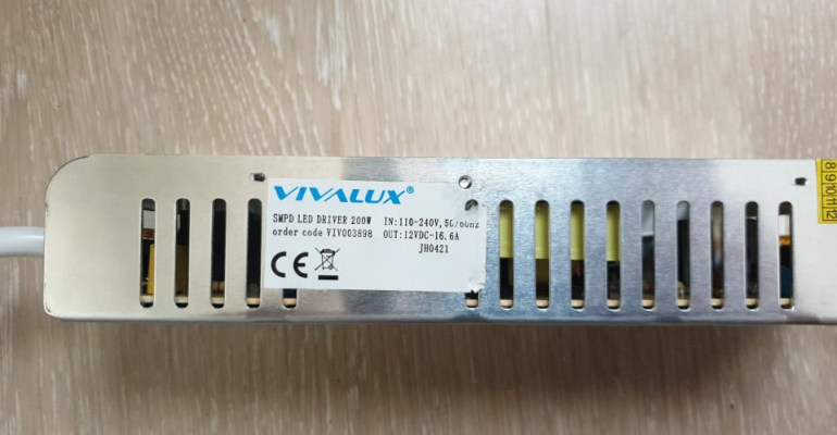
So here's what happened. I have a led power supply:
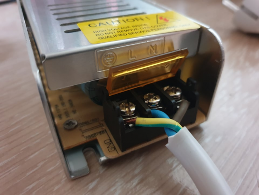
It is meant to take 240v and give back 12 VDC, 16.6 amps. Here's how the power cord is wired:
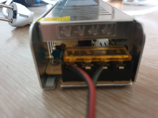
And the cables that should go into my ramps are wired like this:
I need only power for the stepper motors, reprap full smart graphics display, and endstops. From my limited understanding, the first plus-minus pair should be enough?
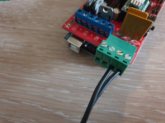
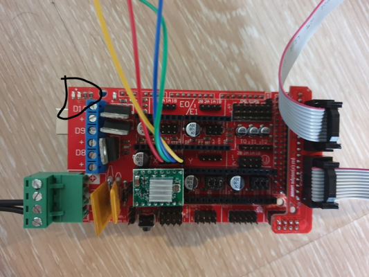
Anyway, I initially wired both power plus-minus pairs (don't know how these are called). According to the voltmeter, the expected voltage flows through the wires - 12 volts. Nothing was happening in the first couple of mins so I started measuring the voltage of the wires. This is when I got several flashes from my LCD display like it was turning on and off, right after that I got some sparks and smoke from my ramps board. You can see from the image below where the fire show appeared.
Of course, I immediately cut off the power.
Just to see if the board is still alive I connected it to my laptop's USB and the LCD display came alive as expected + the orange light on the ramps board that indicates it is turned on. So I'm not sure if I fried something important on the board.
As I mentioned I only need the stepper motors, the display, and the endstops for my project. Don't care about the extruders or fans.
I tried it again this morning with just a single plus-minus pair, but nothing came alive. Like there is no power going through the board. Still, the LCD display and the board (at least the orange light and the reset button) works when powered with the USB from my laptop.
So do you guys have a guess on what I'm doing wrong here, with the power supply or anything else in this setup? What caused the sparks and why the board didn't react to the power supply?
My best guess on what went wrong and caused the sparks is: when I was measuring the voltages I might've inadvertently caused a connection between the plus and minus on the power cables. I would appreciate more opinions though.
Thanks in advance!
I might've burned my ramps 1.4 board (maybe?). The thing is I don't know what I did wrong, so I wanna ask you for your best-educated guesses as I'm pretty new to this stuff.
So here's what happened. I have a led power supply:
It is meant to take 240v and give back 12 VDC, 16.6 amps. Here's how the power cord is wired:
And the cables that should go into my ramps are wired like this:
I need only power for the stepper motors, reprap full smart graphics display, and endstops. From my limited understanding, the first plus-minus pair should be enough?
Anyway, I initially wired both power plus-minus pairs (don't know how these are called). According to the voltmeter, the expected voltage flows through the wires - 12 volts. Nothing was happening in the first couple of mins so I started measuring the voltage of the wires. This is when I got several flashes from my LCD display like it was turning on and off, right after that I got some sparks and smoke from my ramps board. You can see from the image below where the fire show appeared.
Of course, I immediately cut off the power.
Just to see if the board is still alive I connected it to my laptop's USB and the LCD display came alive as expected + the orange light on the ramps board that indicates it is turned on. So I'm not sure if I fried something important on the board.
As I mentioned I only need the stepper motors, the display, and the endstops for my project. Don't care about the extruders or fans.
I tried it again this morning with just a single plus-minus pair, but nothing came alive. Like there is no power going through the board. Still, the LCD display and the board (at least the orange light and the reset button) works when powered with the USB from my laptop.
So do you guys have a guess on what I'm doing wrong here, with the power supply or anything else in this setup? What caused the sparks and why the board didn't react to the power supply?
My best guess on what went wrong and caused the sparks is: when I was measuring the voltages I might've inadvertently caused a connection between the plus and minus on the power cables. I would appreciate more opinions though.

Thanks in advance!
|
Re: Ramps 1.4 power source wiring problems December 24, 2021 05:23AM |
Admin Registered: 13 years ago Posts: 7,000 |
"the first plus-minus pair should be enough?" correct
One thing I cannot see from these images is which connector you have the red stripe going into (which is gnd on the power supply end. red would normally be used to indicate the + side)
The mega has two power system
1) it takes 12v in and passes it through a 5v regulator to make 5v. (if this voltage is present it is used)
2) it take 5v directly from usb if 1 is not present.
the 5v regulator on the mega is really easy to overload and kill.
Unplug the mega
plug 12vv dc into the mega dc in jack, measure any 5v pin for 5v
|
Re: Ramps 1.4 power source wiring problems December 24, 2021 09:56AM |
Registered: 2 years ago Posts: 4 |
Dust, thanks for the answer!
Well, the wires are a little in reverse to what you described. I have the: red -> negative, black -> positive. It shouldn't matter, right? As long as they are connected on the corresponding pins on the ramps.
About the power wires:
* The blue-yellow is the ground.
* Blue is hot.
* Gray is neutral.
I do like your suggestion about measuring the mega to check if I killed the regulator, but I don't have a 12vv dc with the appropriate jack. I have 15vv and more.
Anyway, I tried measuring the ramps while plugged into the power with the mega attached or detached, but the volt matter doesn't give me anything. However, the same is true with the USB plugged when I get the LCD powered up. So I'm not sure how reliable the measurement is. Maybe I'm doing something wrong. When I measure the power supply the volt metter gives me 240vv as it should be. I tried measuring a battery and it also gives me a reading. The absence of a reading with obviously powered ramps is strange (with using the USB as power provider).
So the way I'm going about measuring the ramps is, I choose a random pin and touch it with both wires of the volt metter. Is this the correct way? This is what I saw in the hobbist videos I've came accross.
Would it be save to try what you suggested with 15 volts power supply? I read that the mega can handle up to 20 volts.
|
Re: Ramps 1.4 power source wiring problems December 24, 2021 04:50PM |
Admin Registered: 13 years ago Posts: 7,000 |
|
Re: Ramps 1.4 power source wiring problems December 26, 2021 10:24AM |
Registered: 2 years ago Posts: 4 |
|
Re: Ramps 1.4 power source wiring problems December 26, 2021 02:04PM |
Registered: 6 years ago Posts: 1,863 |
I too killed the regulators.
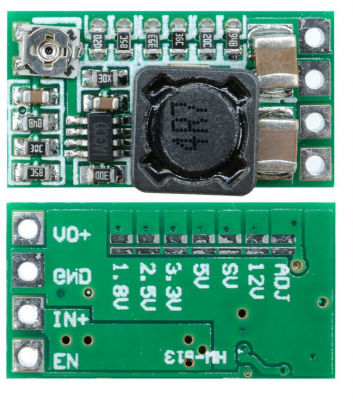
There is many post as to how to replace the AMS1117-5.0 I however replaced with a higher current Buck Converter.
And more here
I previously had replaced the AMS1117-5.0 regulator it was not too long before it fried again, my solution was to increase the regulator current to 3 amps
I choose this buck converter because of 3amp current, preset voltage levels / variable voltage..
From here
Edited 3 time(s). Last edit at 12/26/2021 02:29PM by Roberts_Clif.
Computer Programmer / Electronics Technician
Sorry, only registered users may post in this forum.
