Edges of recengular shapes are OK, but circles are disaster
Posted by usen
|
Edges of recengular shapes are OK, but circles are disaster October 29, 2015 02:10PM |
Registered: 8 years ago Posts: 38 |
Hi,
I built a printer and I used the working principle of coordinate system of Ultimaker, Duet reprap card, GT2 belts and pulleys, and 48 N.cm NEMA17 stepper motors.
There is a little friction due to belts (tension is stiff), but I guess motors have enough torque to overcome the friction problem.
Problem:
If parts have dome or circular lines then I get terrible results. However, rectangular lines give better results. Can you offer any solution or cause for this problem?
(Picture of a printed part is at the attachment.)
Thanks.
|
Re: Edges of recengular shapes are OK, but circles are disaster October 29, 2015 03:03PM |
Registered: 8 years ago Posts: 310 |
|
Re: Edges of recengular shapes are OK, but circles are disaster October 30, 2015 03:52AM |
Registered: 8 years ago Posts: 5,232 |
|
Re: Edges of recengular shapes are OK, but circles are disaster October 30, 2015 05:29AM |
Registered: 8 years ago Posts: 38 |
Quote
deaconfrost
you have the Z stepping calibrated properly? and extruder stepping.
it looks like theres a problem on every part of the printed object rather than just the circular part
Thanks for your answer deaconfrost, our Z axis ball screw is a little bit wrong since ball screw is hard material to work on. Fixing the Z motor was very hard. With your observation, these problems may affect the ball screw with bending, so the bed.
I will try to fix the ball screw problem, then I will share the results from here again.
Quote
deaconfrost
What layer height and nozzle diameter did you use? It looks like you try to print 0.4 layer height with a 0.4 nozzle..
-Olaf
Thanks for your answer Olaf,
we use 0.3 nozzle and 0.1 layer height.
|
Re: Edges of recengular shapes are OK, but circles are disaster October 31, 2015 06:30AM |
Registered: 8 years ago Posts: 38 |
Hi,
I left little free the Z axis, because there was stress on the Z axis shafts. I tested boxer dog figure yesterday and resutls below, layers are not good. Addition to layer quality problem, the last picture as you see, gaps are very bad. There are glides on the gap layers. I used 0.3 mm diameter nozzle and 0.1 mm layer height. What can be reasons that cause these problems?
Note: Orange dog was made another machine (I remembered it was Zortrax with Zortrax brand ABS filaments), Red one was made in my machine with eSun brand ABS filament. I used Cura 15.04.2.
Edited 1 time(s). Last edit at 10/31/2015 06:38AM by usen.
I left little free the Z axis, because there was stress on the Z axis shafts. I tested boxer dog figure yesterday and resutls below, layers are not good. Addition to layer quality problem, the last picture as you see, gaps are very bad. There are glides on the gap layers. I used 0.3 mm diameter nozzle and 0.1 mm layer height. What can be reasons that cause these problems?


Note: Orange dog was made another machine (I remembered it was Zortrax with Zortrax brand ABS filaments), Red one was made in my machine with eSun brand ABS filament. I used Cura 15.04.2.
Edited 1 time(s). Last edit at 10/31/2015 06:38AM by usen.
|
Re: Edges of recengular shapes are OK, but circles are disaster October 31, 2015 07:11AM |
Registered: 10 years ago Posts: 14,672 |
Looks to me that you have backlash in the mechanism, or too much friction, or too little stepper motor torque. What is the rated current of your Nema 17 motors, and what current are you running them at?
Also, do you see a lot of short pauses during printing?
Edited 1 time(s). Last edit at 10/31/2015 07:13AM by dc42.
Large delta printer [miscsolutions.wordpress.com], E3D tool changer, Robotdigg SCARA printer, Crane Quad and Ormerod
Disclosure: I design Duet electronics and work on RepRapFirmware, [duet3d.com].
|
Re: Edges of recengular shapes are OK, but circles are disaster October 31, 2015 07:54AM |
Registered: 8 years ago Posts: 38 |
Quote
dc42
Looks to me that you have backlash in the mechanism, or too much friction, or too little stepper motor torque. What is the rated current of your Nema 17 motors, and what current are you running them at?
Also, do you see a lot of short pauses during printing?
Yes, I thought about the backlash. I use Nema 17 Stepper Motor (Model:42BYGHM809);
48 n/cm torque
3 Voltage
1.7 Amper
1.8 ohm
G-Code is below:
; Configuration file for RepRap Mendel 3
; RepRapPro Ltd
;
; Copy this file to config.g if you have a Mendel 3
; If you are updating a config.g that you already have you
; may wish to go through it and this file checking what you
; want to keep from your old file.
;
; For G-code definitions, see [reprap.org]
;
M111 S0                             ; Debug off
M550 xxxxx           ; Machine name (can be anything you like). With DHCP enabled connect to (example) [reprappromendel3] (machine name with no spaces).
M551 Preprap                        ; Machine password (currently not used)
M540 P0xBE:0xEF:0xDE:0xAD:0xFE:0x14 ; MAC Address
;M552 P0.0.0.0                       ; Un-comment for DHCP
M552 P192.168.1.21                  ; IP address, comment for DHCP
M553 P255.255.255.0                 ; Netmask
M554 P192.168.1.1                   ; Gateway, comment for DHCP
M555 P2                             ; Set output to look like Marlin
G21                                 ; Work in millimetres
G90                                 ; Send absolute corrdinates...
M83                                 ; ...but relative extruder moves
M906 X1400 Y1400 Z1400 E800           ; Set motor currents (mA)
M305 P0 R4700                       ; Set the heated bed thermistor series resistor to 4K7


M305 P1 R4700                       ; Set the hot end thermistor series resistor to 4K7


M569 P0 S0                          ; no Reverse the X motor

M569 P2 S0

M569 P3 S1                          ; Reverse the extruder motor (T0)
M569 P4 S0                          ; Reverse the extruder motor (T1)
M569 P5 S0                          ; Reverse the extruder motor (T2)

M92 X158 Y158 Z1280
M574 X2 S1
M574 Y2 S1
M574 Z2 S1

M92 E97                           ; Set extruder steps per mm
M558 P0                             ;
;G31 Z0.8 P600                       ; Set the probe height and threshold (deliberately too high to avoid bed crashes on initial setup)
M556 S75 X0 Y0 Z0                   ; Put your axis compensation here
M201 X250 Y250 Z50 E500             ; Accelerations (mm/s^2)
M203 X7000 Y7000 Z800 E3600       ; Maximum speeds (mm/min)
M566 X200 Y200 Z30 E20              ; Minimum speeds mm/minute
M563 P0 D0 H1                       ; Define tool 0
G10 P0 S-273 R-273                  ; Set tool 0 operating and standby temperatures
;M563 P1 D1 H2                       ; Define tool 1, uncomment if you have a dual colour upgrade
;G10 P1 S-273 R-273                  ; Set tool 1 operating and standby temperatures, uncomment if you have a dual colour upgrade
;M563 P2 D2 H3                       ; Define tool 2, uncomment if you have a tri colour upgrade
;G10 P2 S-273 R-273                  ; Set tool 2 operating and standby temperatures, uncomment if you have a dual colour upgrade
|
Re: Edges of recengular shapes are OK, but circles are disaster October 31, 2015 07:55AM |
Registered: 8 years ago Posts: 778 |
|
Re: Edges of recengular shapes are OK, but circles are disaster October 31, 2015 08:22AM |
Registered: 8 years ago Posts: 38 |
|
Re: Edges of recengular shapes are OK, but circles are disaster October 31, 2015 08:25AM |
Registered: 10 years ago Posts: 14,672 |
Quote
usen
Yes, I thought about the backlash. I use Nema 17 Stepper Motor (Model:42BYGHM809);
48 n/cm torque
3 Voltage
1.7 Amper
1.8 ohm
G-Code is below:
...
M906 X1400 Y1400 Z1400 E800 ; Set motor currents (mA)
Your motor torque should be OK as you are running your 1.7A motors at 1.4A. Actually, 1.4A for all three axes is rather high for a Duet, so I suggest you use a fan to cool the Duet PCB if you don't already.
Try jogging the head 0.1mm at a time in the X and Y directions. Can you see the head move on each jog, or do you sometimes have to jog it 2 or 3 times before the head moves?
Also I agree with the previous comment that the extrusion looks uneven in volume.
Finally, I see that your print is shorter than the one you are comparing it to. This could indicate that your Z axis is sometimes missing steps. Try reducing the Z max speed from 800 to 250 in the M203 command, and the Z acceleration from 50 to 20 in the M201 command.
Large delta printer [miscsolutions.wordpress.com], E3D tool changer, Robotdigg SCARA printer, Crane Quad and Ormerod
Disclosure: I design Duet electronics and work on RepRapFirmware, [duet3d.com].
|
Re: Edges of recengular shapes are OK, but circles are disaster November 06, 2015 03:40AM |
Registered: 8 years ago Posts: 38 |
Quote
dc42
Quote
usen
Yes, I thought about the backlash. I use Nema 17 Stepper Motor (Model:42BYGHM809);
48 n/cm torque
3 Voltage
1.7 Amper
1.8 ohm
G-Code is below:
...
M906 X1400 Y1400 Z1400 E800 ; Set motor currents (mA)
Your motor torque should be OK as you are running your 1.7A motors at 1.4A. Actually, 1.4A for all three axes is rather high for a Duet, so I suggest you use a fan to cool the Duet PCB if you don't already.
Try jogging the head 0.1mm at a time in the X and Y directions. Can you see the head move on each jog, or do you sometimes have to jog it 2 or 3 times before the head moves?
Also I agree with the previous comment that the extrusion looks uneven in volume.
Finally, I see that your print is shorter than the one you are comparing it to. This could indicate that your Z axis is sometimes missing steps. Try reducing the Z max speed from 800 to 250 in the M203 command, and the Z acceleration from 50 to 20 in the M201 command.
Hi,
I changed values M201 and M203 as you said. Results are below. As you know, orange is from another machine. The dog in the middle previous problematic one. Rightest is the last test after calibration. Shifts in layers are over, but gaps problem are continuing for example in the head of the dog. This problem is seen in the same layer especially when I compare last test (rightest) with previous test (middle).


|
Re: Edges of recengular shapes are OK, but circles are disaster November 06, 2015 04:49AM |
Registered: 8 years ago Posts: 778 |
|
Re: Edges of recengular shapes are OK, but circles are disaster November 06, 2015 04:53AM |
Registered: 10 years ago Posts: 14,672 |
Try printing something simpler, such as a 25mm calibration cube. That should make it easier to work out what is going on.
Large delta printer [miscsolutions.wordpress.com], E3D tool changer, Robotdigg SCARA printer, Crane Quad and Ormerod
Disclosure: I design Duet electronics and work on RepRapFirmware, [duet3d.com].
Large delta printer [miscsolutions.wordpress.com], E3D tool changer, Robotdigg SCARA printer, Crane Quad and Ormerod
Disclosure: I design Duet electronics and work on RepRapFirmware, [duet3d.com].
|
Re: Edges of recengular shapes are OK, but circles are disaster November 06, 2015 05:33AM |
Registered: 9 years ago Posts: 445 |
From the looks of those pictures and assuming the other printer is calibrated correctly, I'd have to say that you need to perform a calibration of your printer.
Your fist print was smaller than the reference, your new print is larger and elongated in the nose direction.
So you need to print something easy like a calibration cube (as previous poster mentioned) and then measure it and recalculate your steps/mm.
Your fist print was smaller than the reference, your new print is larger and elongated in the nose direction.
So you need to print something easy like a calibration cube (as previous poster mentioned) and then measure it and recalculate your steps/mm.
|
Re: Edges of recengular shapes are OK, but circles are disaster November 06, 2015 10:43AM |
Registered: 8 years ago Posts: 38 |
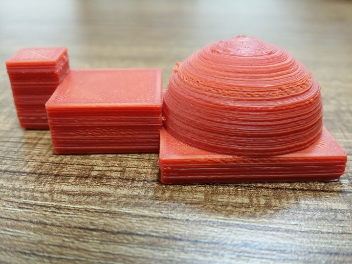
I printed a calibrate shape that includes squares and a cylinder with different sizes. I measured the sizes and results below. I guess extruder does not work well. Could it be another problem?


|
Re: Edges of recengular shapes are OK, but circles are disaster November 06, 2015 10:49AM |
Registered: 9 years ago Posts: 445 |
|
Re: Edges of recengular shapes are OK, but circles are disaster November 06, 2015 11:00AM |
Registered: 8 years ago Posts: 38 |
Quote
Koenig
The round object is it 15mm in all directions?
What are the measurements of the biggest square in both directions?
From bottom to top layer: 14.92 - 14.95 - 14.96 - 15 - 14.97 mm
Square size:
10x10x15 mm
20x20x10 mm
30x30x5 mm (I measured 29.63x29.75x4.92 mm)
Cylinder size:
D15xH15
Edited 1 time(s). Last edit at 11/06/2015 11:03AM by usen.
|
Re: Edges of recengular shapes are OK, but circles are disaster November 06, 2015 11:16AM |
Registered: 9 years ago Posts: 445 |
Quote
usen
Quote
Koenig
The round object is it 15mm in all directions?
What are the measurements of the biggest square in both directions?
From bottom to top layer: 14.92 - 14.95 - 14.96 - 15 - 14.97 mm
Square size:
10x10x15 mm
20x20x10 mm
30x30x5 mm (I measured 29.63x29.75x4.92 mm)
Cylinder size:
D15xH15
So you need to adjust your XY steps some (based on your measurements on the big square)
Perhaps your Z steps as well.
It also looks like some under extrusion on your perimeters, might need to calibrate the extruder as well.
Post your slicer settings to see if there's anything there.
|
Re: Edges of recengular shapes are OK, but circles are disaster November 06, 2015 11:38AM |
Registered: 8 years ago Posts: 38 |
Quote
Koenig
Quote
usen
Quote
Koenig
The round object is it 15mm in all directions?
What are the measurements of the biggest square in both directions?
From bottom to top layer: 14.92 - 14.95 - 14.96 - 15 - 14.97 mm
Square size:
10x10x15 mm
20x20x10 mm
30x30x5 mm (I measured 29.63x29.75x4.92 mm)
Cylinder size:
D15xH15
So you need to adjust your XY steps some (based on your measurements on the big square)
Perhaps your Z steps as well.
It also looks like some under extrusion on your perimeters, might need to calibrate the extruder as well.
Post your slicer settings to see if there's anything there.
Our Cura settings below:


|
Re: Edges of recengular shapes are OK, but circles are disaster November 06, 2015 12:50PM |
Registered: 10 years ago Posts: 14,672 |
The reason I suggested printing calibration objects was not to check the sizes, but to look at the print quality. Your calibration object prints show the same holes in some places that you get with the dog.
First, can you confirm that you are printing the objects from the SD card, and not from Pronterface etc. over the USB port?
Second, have you calibrated the extruder steps/mm?
Third, is there any evidence of the extruder skipping steps? If so, you will see the extruder gears (if you have a geared extruder) jumping backwards.
Large delta printer [miscsolutions.wordpress.com], E3D tool changer, Robotdigg SCARA printer, Crane Quad and Ormerod
Disclosure: I design Duet electronics and work on RepRapFirmware, [duet3d.com].
|
Re: Edges of recengular shapes are OK, but circles are disaster November 06, 2015 12:53PM |
Registered: 9 years ago Posts: 445 |
|
Re: Edges of recengular shapes are OK, but circles are disaster November 06, 2015 04:51PM |
Registered: 9 years ago Posts: 445 |
Quote
dc42
The reason I suggested printing calibration objects was not to check the sizes, but to look at the print quality. Your calibration object prints show the same holes in some places that you get with the dog.
Sort of for me as well, but it is still important to know if the objects are right size to get the extrusion right...
My though was that since his latest dog looked better in some places and under extruded in other places his extruder might be calibrated but it doesn't keep up since to model is bigger than it is supposed to.
|
Re: Edges of recengular shapes are OK, but circles are disaster November 08, 2015 04:37AM |
Registered: 8 years ago Posts: 38 |
|
Re: Edges of recengular shapes are OK, but circles are disaster November 08, 2015 05:59AM |
Registered: 8 years ago Posts: 778 |
You have to measure what comes out of the extruder and adjust the stepping accordingly.
Works best with the cold extrusion prevent disabled in the firmware as you can play back and forth without the hotend and wasting filament.
Mark the filament and extrude 10mm - measure it.
It is not 10mm +-0.3mm already adjust the stepping a bit.
Extrude 30mm and check again.
If required adjust stepping.
Extrude 50mm and check.
Adjust stepping, check again, adjust stepping until you are spot on.
|
Re: Edges of recengular shapes are OK, but circles are disaster November 15, 2015 10:09AM |
Registered: 8 years ago Posts: 38 |
Quote
Downunder35m
You have to measure what comes out of the extruder and adjust the stepping accordingly.
Works best with the cold extrusion prevent disabled in the firmware as you can play back and forth without the hotend and wasting filament.
Mark the filament and extrude 10mm - measure it.
It is not 10mm +-0.3mm already adjust the stepping a bit.
Extrude 30mm and check again.
If required adjust stepping.
Extrude 50mm and check.
Adjust stepping, check again, adjust stepping until you are spot on.
I arranged extruder by changing M97. Extruder extrudes exactly what I want. I printed a new calibration cube and results are below. There are leaps when it fills inner and wall, as you see. And corners are not good, not parallel or smooth.


|
Re: Edges of recengular shapes are OK, but circles are disaster November 15, 2015 12:51PM |
Registered: 10 years ago Posts: 580 |
I think your primary issue is with extrusion, there are multiple indicators:
- Gaps in printing
- That diagonal pattern that you see, with blobbing. I believe this is caused by a slight temporary underextrusion on the previous layer, and when the next layer goes over that spot it doesn't quite have enough foundation to stick to, and so a blob forms that eventually sticks a short distance later. Then on the next layer the blob sticks to the beginning of the lower blob, and so it builds up at an angle.
- Don't trust that your hot-end thermistor is exactly right. Try slightly higher and lower temps to see what that particular filament needs to flow correctly.
- As stated this could also be caused by some blockage - pull the filament out while the hot end is cooling and it could remove it.
- Watch the extruder temp while it's printing - is it consistently at the right temp? If not you may need to do a PID calibration.
- Watch the heatbed temp as well.
- Make sure the filament drive gear is not getting clogged.
- You can also experiment with a slightly wider or narrower extrusion width to see what your extruder likes, or a slightly taller layer height.
[Edit - more]
- Make sure the extruder is clamping the filament securely enough
- Put marks on the extruder stepper shaft and whatever it's connected to -to make sure it's not slipping (flat ground on shaft)?
- As stated previously - watch it the extruder gear carefully to see if it is slipping back. I think it's a temp issue tho.
There is a very evident repeating wave pattern in the perimeter.
- You can measure the distance. Is this distance related to the ball screw's pitch?
Edited 1 time(s). Last edit at 11/15/2015 01:40PM by Paul Wanamaker.
My printer: Raptosaur - Large Format Delta - [www.paulwanamaker.wordpress.com]
Can you answer questions about Calibration, Printing issues, Mechanics? Write it up and improve the Wiki!
|
Re: Edges of recengular shapes are OK, but circles are disaster November 26, 2015 04:27AM |
Registered: 10 years ago Posts: 444 |
|
Re: Edges of recengular shapes are OK, but circles are disaster November 26, 2015 05:46PM |
Registered: 8 years ago Posts: 4 |
|
Re: Edges of recengular shapes are OK, but circles are disaster November 27, 2015 09:10AM |
Registered: 9 years ago Posts: 752 |
In the last print when looking at the layers it seems to me the layer height is varying in the same pattern as the corner wobble. This could indicate a z motor current/skipping steps problem, or the heated bed uses bang/bang control expanding/contracting raising and lowering the bed. What motor drivers/stepsticks are you using? What are the z steps currently set at? What is the calculated z steps and what's the difference? If it's more than 1% it's likely skipping steps. Threaded rods usually have an accuracy of about 0.05 to 0.1%. If pulleys and timing belts are usef to drive the threafed rod the deviation can get bigger. What's the microstep configured at? Does the motor spin smoothly when running it slowly? Try
G1 z5 f15
What is the z speed and acceletation settings? Try a lower setting.
The holes can be the result of retractions being too long, trapping air in the filament which pops when continuing printing. It could also be bubbles in the filament itself, or moist buildup. You can try putting a couple of meters of filament in an oven at 40 degrees for pla, 75 for abs for a couple of hours and see if that improves things.
Did you try calibrating extrusion with? It may be you're over extruding. If that leaves holes in the top infill you may have backlash in the x an y axes.
See
calibrate extrusion width
Edited 1 time(s). Last edit at 11/27/2015 09:24AM by imqqmi.
--
Kind regards
Imqqmi
NFAN CoreXY printer:
[reprap.org]
|
Re: Edges of recengular shapes are OK, but circles are disaster November 29, 2015 06:40AM |
Registered: 10 years ago Posts: 444 |
Did not see the different Z heights. You are right, it is changing. Almost certainly something changing heights in a regular pattern, like the heat bed. This would be easily visible on the lcd readout.
The holes however are in regular positions, so likely that the infill at those locations is affecting it.
The holes however are in regular positions, so likely that the infill at those locations is affecting it.

Sorry, only registered users may post in this forum.