Problems with circle perimeter
Posted by chngyian
|
Problems with circle perimeter February 07, 2016 05:10AM |
Registered: 10 years ago Posts: 128 |
Hello guys, need some help with the perimeters of circle.
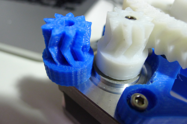
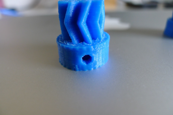
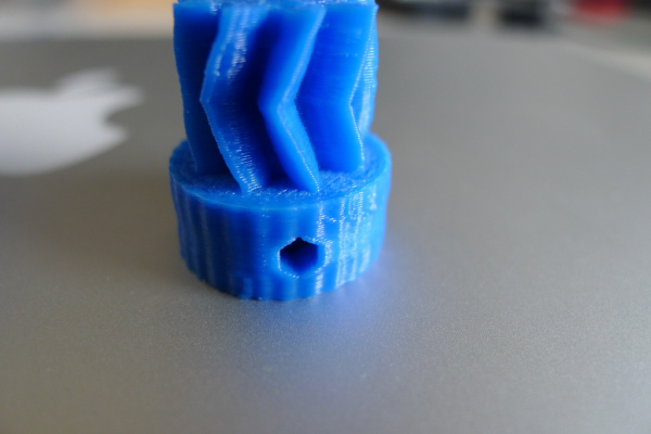
Here's what happened, I printed the ones in white a few years back with KISSlicer. Now, since it's kind of dead I decided to switch to slic3r.
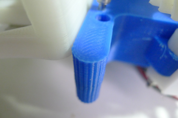
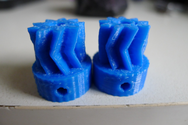
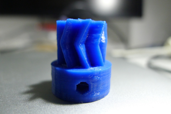
Although the STLs are the same, I am getting polygons instead of a true circle on the blue ones. Just wondering how do I go around solving this problem
Spent a few hours google but can't seem to find anything useful.
Edited 1 time(s). Last edit at 02/07/2016 05:13AM by chngyian.
|
Re: Problems with circle perimeter February 07, 2016 06:54AM |
Registered: 9 years ago Posts: 1,873 |
|
Re: Problems with circle perimeter February 08, 2016 07:09AM |
Registered: 9 years ago Posts: 125 |
Attach your .stls. I have round circles with Cura and Slic3r. Or almost... with 96 sides and something. Moving . stl back and forth between programs can reduce circle sides. Blender exported 32 side circle improted to Sketchup changed to 24 sides (STL). STL is never full circle...I think.
Prusa i3, Ramps 1.4. Catnozzle 0.4mm
SketchUp - Enveloping Globoid Worm Gear - Part One - 3D Printed: [youtu.be]
DesignSpark Mechanical & more precise screw thread: [youtu.be]
Nicer Screw Thread In SketchUp ( Bolts,Nuts): [youtu.be]
How To Model A Heart Shape In SketchUp: [youtu.be]
How To Draw 3D Printable Snap Fit Ball Joint In SketchUp: [youtu.be]
|
Re: Problems with circle perimeter February 08, 2016 08:15AM |
Registered: 9 years ago Posts: 1,873 |
|
Re: Problems with circle perimeter February 08, 2016 11:58AM |
Registered: 10 years ago Posts: 580 |
|
Re: Problems with circle perimeter February 10, 2016 01:56AM |
Registered: 10 years ago Posts: 128 |
Quote
Paul Wanamaker
Hi Chngyian,
When you attach STLs please first slice with Output Options, Verbose Gcode turned on.
You may have to link them to Dropbox etc if they are over 514k.
I can view the segment details in my gcode debugger.
[www.dropbox.com]
the link to the verbose gcode is above.
[www.dropbox.com]
link to the stl is above
one update is that when I tried to print again, it seems that the edges are better this time but the polygons are still visible.
the difference is that for the earlier print, I was trying to print with several other stls on the platter. I'm not too sure if this will affect the quality of the stl files.
for the second print, i only printed the small gear alone.
|
Re: Problems with circle perimeter February 10, 2016 07:17AM |
Registered: 11 years ago Posts: 5,780 |
I looked at the STL file in Meshlab. Your printer is trying to do what the STL contains- Notice two corners in the base right near the grub screw hole- your print has two corners there, too. It looks like your printer may be overextruding a bit- did you use the correct filament diameter when you sliced? Have you calibrated the extruder?
The STL file came from Sketchup- that's why it had to be "fixed" by netfabb. Sketchup sucks and will almost always leave you with corners on your curves unless you take special pains to prevent it. It will almost always require "fixing" the STL because, well, it sucks. There's better CAD called DesignSpark Mechanical that is free and has a very similar user interface, but does much more and works much better for designing mechanical parts. You won't have to "fix" the STL files it produces.
Edited 1 time(s). Last edit at 02/10/2016 07:17AM by the_digital_dentist.
Ultra MegaMax Dominator 3D printer: [drmrehorst.blogspot.com]
|
Re: Problems with circle perimeter February 10, 2016 11:50AM |
Registered: 10 years ago Posts: 128 |
Quote
the_digital_dentist
I looked at the STL file in Meshlab. Your printer is trying to do what the STL contains- Notice two corners in the base right near the grub screw hole- your print has two corners there, too. It looks like your printer may be overextruding a bit- did you use the correct filament diameter when you sliced? Have you calibrated the extruder?
The STL file came from Sketchup- that's why it had to be "fixed" by netfabb. Sketchup sucks and will almost always leave you with corners on your curves unless you take special pains to prevent it. It will almost always require "fixing" the STL because, well, it sucks. There's better CAD called DesignSpark Mechanical that is free and has a very similar user interface, but does much more and works much better for designing mechanical parts. You won't have to "fix" the STL files it produces.
Hi digital dentist,
I just started using 0.5 extrusion width on 0.4 nozzle hoping to improve the layer adhesion. Not too sure if this causes it, but I'll change and see if it improves.
As for filament diameter and extruder, I usually calibrate by looking at the top layer surface and adjust such that I can achieve a "flat" top layer without any signs of overextrusion. Please correct me if this is not a good way to do so.
Regarding the STL, i have absolutely no experience at editing STLs and this is an STL that I got from thingiverse. If i understand correctly, you are saying that netfabb can smooth out the polygons by "fixing"?
On a side note, if you know any resource or articles on STLs processing please point me in the direction. I have just started reading up on meshmixer etc, and would really like to try them out.
|
Re: Problems with circle perimeter February 10, 2016 01:35PM |
Registered: 11 years ago Posts: 5,780 |
Over extrusion has nothing to do with setting the line widths. It's fine and good to set the line width wider than the nozzle (and a big problem setting it narrower than the nozzle). Calibrating the extruder means checking that line width to make sure you get what you told the slicer to do. There are a couple different techniques, but start with the reprap wiki calibration guide. You can either use the "e steps fine calibration" procedure there or print a single walled object such as a 15mm cube as a spiral vase in slic3r, then measure the wall thickness. If it's too thick, use the flow control to adjust it to the correct width.
It all comes down to the actual diameter of the filament vs the nominal diameter (1.75 or 3.0 mm). Actual diameter usually isn't the nominal diameter so you are always dealing with over/under extrusion if you slice using the nominal diameter. If you use the single walled object technique I described above, you will want to do that for every new spool of filament. Let's say you tell slicer that the filament is 1.75mm diameter, and to print a 0.5mm line and it gives you a 0.4 mm line. You need to increase the flow by 25%, so set the flow to 1.25 (target dia/actual dia). Mark that flow value on the spool because you'll need it the next time you print with that filament.
An alternative approach that does not involve printing test objects is to measure the filament at 20-30 places and average the value (you must do this before calibrating!). If you use that value for filament diameter when you slice, line widths will come out right (assuming you've calibrated the extruder accurately). Mark that filament diameter on the spool because you'll need it every time you print from that spool. You should measure the filament this way when you calibrate the extruder.
You can make your gcode completely indifferent to filament diameter by using volumetric extrusion. You tell the slicer that the filament is 1.128379 mm no matter what it actually is. You slice and export the gcode. When you print the part, you enter the actual filament diameter using the M200 command if you are using host software or enter it via the LCD control panel if your printer controller board runs smoothieware (I don't know if other firmwares have that function available via LCD). That will allow you to change spools of filament, which will probably be different diameters, without reslicing.
As far as I know, netfabb doesn't smooth out the STL file. What it does is fill holes and delete overlaps that routinely occur in Sketchup models. A file that has been processed by netfabb gets "fixed" appended to the file name. Prior to repairs, the STL file would have been unprintable. Why people still use Sketchup for 3D printing models is beyond me. People are weird. You might be able to smooth a rough STL file with Meshlab, but I am a rank amateur using Meshlab so I can't help you with that. There are a lot of Meshlab tutorials on youtube and scattered around the web.
Ultra MegaMax Dominator 3D printer: [drmrehorst.blogspot.com]
|
Re: Problems with circle perimeter February 10, 2016 02:54PM |
Registered: 10 years ago Posts: 580 |
I'm going to take this from a different perspective.
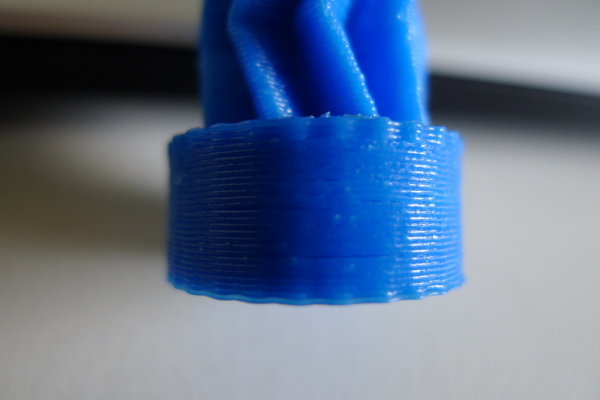
I'm paying attention to the scalloped look in the lower portion.
I'm not convinced this is a model problem for several reasons:
- The same model printed fine before in a different slicer.
- The model prints differently with a different number of parts printed at once.
- Looking at the segments individually, they are OK.
So I looked at the gcode and noticed this at the top:
You are using 40mm/s for all speeds.
So there is a huge difference in extrusion rate between inner and outer perimeters, and a very very wide inner perimeter width is being used.
Note that the max sane extrusion width for a .40 nozzle is .40 * 1.70 = .68mm. The recommended minimum is width is .42mm. (These are from the recommendations of the developer of Slic3r).
Layer height should be < 80% of nozzle diameter, which would be .32mm. In general you would get a better print with .20mm though.
Since the segments of the circle end at the same points along the circle, combined with the high extrusion rate and perhaps your acceleration settings - I speculate that extra extrusion is piling up and pushing the perimeters out at those points.
So here are my recommendations:
- Do the extrusion fine tuning as recommended.
- Set your extrusion widths and speeds so the extrusion rate is more constant. Extrusion rate = layer height x extrusion width x feed rate. So you would need to slow down wide extrusions.
- Set your perimeter extrusion width below .68mm and use a slower speed.
- Set your external perimeter width to .42.
You could also try printing external perimeters first - note that this can be tricky with overhangs.
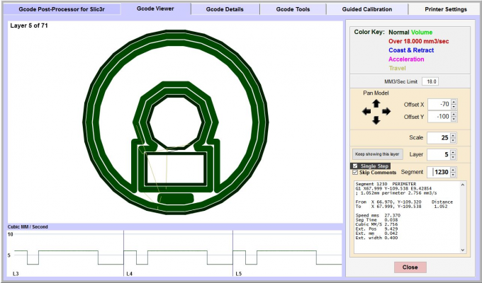
Here is a layer shown in my debugger. You can see at the bottom the differences in extrusion rate within each layer.
Hope that helps.
My printer: Raptosaur - Large Format Delta - [www.paulwanamaker.wordpress.com]
Can you answer questions about Calibration, Printing issues, Mechanics? Write it up and improve the Wiki!
I'm paying attention to the scalloped look in the lower portion.
I'm not convinced this is a model problem for several reasons:
- The same model printed fine before in a different slicer.
- The model prints differently with a different number of parts printed at once.
- Looking at the segments individually, they are OK.
So I looked at the gcode and noticed this at the top:
; external perimeters extrusion width = 0.40mm
; perimeters extrusion width = 0.80mm
; infill extrusion width = 0.48mm
; solid infill extrusion width = 0.48mm
; top infill extrusion width = 0.48mm
You are using 40mm/s for all speeds.
So there is a huge difference in extrusion rate between inner and outer perimeters, and a very very wide inner perimeter width is being used.
Note that the max sane extrusion width for a .40 nozzle is .40 * 1.70 = .68mm. The recommended minimum is width is .42mm. (These are from the recommendations of the developer of Slic3r).
Layer height should be < 80% of nozzle diameter, which would be .32mm. In general you would get a better print with .20mm though.
Since the segments of the circle end at the same points along the circle, combined with the high extrusion rate and perhaps your acceleration settings - I speculate that extra extrusion is piling up and pushing the perimeters out at those points.
So here are my recommendations:
- Do the extrusion fine tuning as recommended.
- Set your extrusion widths and speeds so the extrusion rate is more constant. Extrusion rate = layer height x extrusion width x feed rate. So you would need to slow down wide extrusions.
- Set your perimeter extrusion width below .68mm and use a slower speed.
- Set your external perimeter width to .42.
You could also try printing external perimeters first - note that this can be tricky with overhangs.
Here is a layer shown in my debugger. You can see at the bottom the differences in extrusion rate within each layer.
Hope that helps.
My printer: Raptosaur - Large Format Delta - [www.paulwanamaker.wordpress.com]
Can you answer questions about Calibration, Printing issues, Mechanics? Write it up and improve the Wiki!
|
Re: Problems with circle perimeter February 12, 2016 10:28PM |
Registered: 10 years ago Posts: 128 |
Paul, thanks for your input!
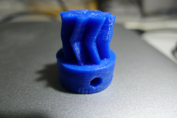
The picture above is after following your settings, much much better although the polygons are still visible.
And then I decided since I was printing so many of these small gears, I might as well make them usable. (since the ones printed previously have no infill)
So I made 20% infill and above was the print. The polygons were back with rage. Damn.
And then I stared really hard at the print with your recommended extrusion width. When I looked really closely, I realised that the polygons were most visible at the top few and bottom few layers but was fine in between. These layers are the top and bottom solid layers.
Not too sure what this means, could be cooling fan or could be the print speed. I need more experiments.
|
Re: Problems with circle perimeter February 13, 2016 07:27AM |
Registered: 9 years ago Posts: 1,873 |
I'm leaning towards over extrusion. In the solid layers there's no where for the excess to go, so it can pile up around the edges creating waves. In the non solid areas there is space inside for the excess to expand into, so there is at least the possibility of a well formed perimeter. Problems with the theory include the fact that the perimeters are normally done first, so I wouldn't expect the infill to make so much difference, but I've seen it first hand where it does, so we'll chalk that up to incomplete understanding 
At least in one of the photos, there are signs of over extrusion on the top of the cylinder (inlining the image doesn't seem to be working great, but here's the link):
[s1045.photobucket.com]

At least in one of the photos, there are signs of over extrusion on the top of the cylinder (inlining the image doesn't seem to be working great, but here's the link):
[s1045.photobucket.com]
|
Re: Problems with circle perimeter February 13, 2016 06:28PM |
Registered: 9 years ago Posts: 1,873 |
|
Re: Problems with circle perimeter February 21, 2016 11:32AM |
Registered: 10 years ago Posts: 128 |
And so, my problem is solved. It turns out that lowering the print speed made the problem go away.
The clue that gave it away was that only the layers without infill were fine. This is because with 3 perimeters, the cooling setting on slic3r slowed the printing speed down to give allowance for cooling. Hence the layers without infill were pretty "circle".
On the other hand, the layers with infill had a longer layer print time so it went ahead at 40mm/s. This resulted in polygons rather than circle.
The temporary solution I came up with is to slow down the external perimeters to 25mm/s. But I would really like to find out the true reason why.
I am blind guessing the acceleration settings, it could be set so low that it spends a longer time at the edges of the polygon and this resulted in a polygon instead of "circle".
|
Re: Problems with circle perimeter February 21, 2016 12:04PM |
Registered: 11 years ago Posts: 5,780 |
Interesting. Glad to see you figured it out.
Ultra MegaMax Dominator 3D printer: [drmrehorst.blogspot.com]
Ultra MegaMax Dominator 3D printer: [drmrehorst.blogspot.com]
Sorry, only registered users may post in this forum.
